Just to get the ball rolling..
One project I have been working on, is trying to get an OV7670 camera working with a STM32 board
I’ve had the OV7670 camera board for at least a year, but I found that it was almost unusable on the Uno or Mega Arduino, because the processor speed (16Mhz) is too low on those AVR boards and they don’t have enough RAM to hold a useful image
The other problem with using an AVR Arduino with those camera modules, is that the Non-FIFO module requires an external clock of at least 10Mhz (I think some people manage to get them to work at 8MHz, but I think this is lower than the spec allows)
I know that it is possible to get the AVR’s to output a clock, but one method requires special fuses to be blown in the chip to facilitate this, so its hard to just use the Arduino IDE to do this
The STM32 boards look a much better option for connection to the camera, because the bigger processors have up to 64k RAM, which is plenty to store a reasonable resolution frame, they can also generate the 10Mhz (or higher clock) just using PWM, and of course the processor speed of 72Mhz on all the STM32F103 also allow them to read and process the image data more easily that is possible on a 16Mhz AVR board.
Anyway, so much for the theory.
So far, I have managed to generate the clock, and also communicate with the camera via its SCCB bus (a derivation of I2C), however I have had less luck reading an image.
I will post code and an update on this when I have more time.
OV7670 I2C is non standard, it wont run at the speed of the I2C that the STM32 uses (250kbps)
So I had to slow it down.
I found the code I was messing around with, and it does communicate via Wire aka SCCB to the camera, but I’ve no idea what setup is being sent to the camera, as I just took some example code, and the camera has hundreds of registers that need to be setup correctly for it to work well.
Also the pixel grabbing code is too slow, even for the STM32 running at 72Mhz, having to monitor the HREF and VSYNC pins as well as waiting for the rising edge of the pixel clock doesnt really work.
In the code I posted, it doesnt even grab the pixel, if you see on line 392 its just incrementing the pixel counter, but this is where you need to put the code to read the pixel.
i.e I never get a consistent pixel count.
I think what MrArduino does its not to bother checking HREF, all he does is wait for VSYNC then count the number of rising edges on the pixel clock (as just looking for rising edges and incrementing or decrementing a counter is possible even on a 16Mhz AVR board.
Really what we need to do is use a Timer input and the DMA to get the data every rising edge of the pixel clock, but I’ve not had time to work out how to setup both a Timer channel and also a DMA channel to do this.
I know Victor_pv is busy with other DMA and Timer related stuff, but when he’s finished with that, he may be able have some ideas on how to setup the code to do the pixel grabbing in DMA,
BTW. To grab the pixels effeciently, you need all 8 bits of the pixel on the same port e.g. PA or PB or PC etc
So I ended up using a STM32F103RCT board, as this has 8 GPIO’s on one of the ports
Anyway,
At least you may be able to communiucate over SCCB with your camera
PS. It won’t communicate over SCCB unless you supply it with the 10Mhz clock
My code outputs the clock, but I’ve not looked it it for months, so I can’t remember which pin its on.
So you’ll need to read the code to work it out
this would be one of my future projects. I had one Pro Mini working with the camera (w/o FIFO), I could really read pixels showing a real picture!
In that setup I just pushed the pixel data over UART->WiFi bridge to a PHP script (Apache server) which than processed further the image.
Unfortunately, the data link was not always reliable, and the speed awfully slow.
This time I will try to read only a subset of the whole image so that it fits in RAM. Alternatively, I could also use my external 64Mbit SRAM over SPI to temporarily store image data.
Btw, is there any external SRAM lib available for STM32? Maybe even with DMA transfer?
I will test you code and let you know if I can get some usable results.
Cheers,
Steve
I finally managed to get an image from OV7670 camera chip.
I used the SW from Roger as starting point. However, the camera settings won’t do the right thing.
I had another project based on ATmega328P pro mini which worked, and I imported those settings.
And also reworked the I2C part which didn’t work at the beginning (i don’t know exactly why…).
My requirements were:
– use only gray scale 8 bit
– use lowest resolution to fit data into RAM
– use maximum pixel clock speed which still enables SW polling of PCLK.
So I came up to this attached version. The pinning is documented in the INO file.
The image data is sent out to serial port. To visualize it, first copied the serial output to Notepad++, then used the plugin converter HEX->ASCII. Saved the data as img.raw.
Then I used ImageJ (http://imagej.nih.gov/ij/download/win32 … re8-64.zip), File->Import->RAW, 80(lines)x160(pixels), 8 bit.
I also attached a recorded picture in the package for reference.
Have fun!
ps. next step will be to OCR the picture on STM32 ![]()
I know the getting the settings right seems to need some sort of Voodoo magic ![]()
( because there are so many of them)
I’m sure that it would be possible for the STM32 to DMA the image from the camera, but I never got around to figuring out how to setup all the regsiters that would be needed do that
But its good you have got something working.
The image seems to be 160×80, not 80×160. My brain OCR output is 3487!
Maybe you can drop a passage outputting binary on serial instead of ASCII hex.
@zoomx – the used camera setting allows 160 (pixels) x 120 (lines), out of which I only use the first 80 lines, the resulting image geometry fits to my need.
@Roger – I also made thoughts about to use DMA, but as long as don’t need high frame rate (only one steady picture), I finally implemented the simplest solution.
Anyway, to use DMA doesn’t seem to be much complicated (theoretically), the trick is to set up a timer in slave trigger mode (i think) to generate the interrupt for DMA as PCLK rising edges are detected. For this, the camera should be set to generate PCLK only when HREF is active (I have the respective line commented out in the INO file).
The relevant command is:
//wrReg(REG_COM10, BIT5); //pclk does not toggle on HBLANK
commented out in my INo file.
Thanks. Thats good to know
I have been trying to get this functional on the Arduino (but not yet).
I would be glad to try this on my Stm32 ebay boards.
Below is the link:
https://forum.arduino.cc/index.php?topic=159557.720
The code should be easy to convert from Arduino to Stm32.
Below is the Arduino Code and Schematic, without a needed Level Converter for PCLK.
I not sure what was your question.
Have you read the previous posts?
This gives you more info, including code:
http://www.stm32duino.com/viewtopic.php?f=19&t=4#p11278
– for anybody interested.
For example, the Stm32 example code listed here only provides the 160×80 resolution,
– while the Arduino code provides Vga 640/320×240 Modes – which may be helpful modifications.
I just posted this – and have not dug up my Stm32 boards to try it yet.
I also have some 320×240 ili9341 LCDs that I can use with it.
– Just Ov7670 connected to Stm32F103c8 ebay board.
https://www.youtube.com/watch?v=TqSY6FETuos
He made a huge thing 10fps on Arduino.
I will be trying to run it on maple mini.
He has all code on github also for stm!
worth to try!
https://www.youtube.com/watch?v=TqSY6FETuos
He made a huge thing 10fps on Arduino.
I will be trying to run it on maple mini.
He has all code on github also for stm!
worth to try!
If I get chance I will try it as well.
Using a ST7735 based display.
This one is Arduino nano based.
https://github.com/indrekluuk/LiveOV7670
I have one with and one without FIFO.
I’m not sure which version these repo’s use, but I can find out.
From what I recall the FIFO doesnt help a lot in the image capture as you still seem to need to read the data at a very high rate, however I presume to send a frame over a slow link e.g. USB serial, it may be possible to capture one frame to FIFO and then read that frame multiple times, offsetting by one additional line each time the FIFO is read (and only reading one line)
But I also can’t remember if the FIFO holds a whole frame or list 1 line, but its a large buffer (384k)
http://www.averlogic.com/pdf/AL422B_Flyer.pdf
So I presume its a whole frame.
// configure PA8 to output PLL/2 clock

#ifndef OV7670_INIT_CLOCK_OUT

#define OV7670_INIT_CLOCK_OUT \

gpio_set_mode(GPIOA, 8, GPIO_AF_OUTPUT_PP); \

*(volatile uint8_t *)(0x40021007) = 0x7

#endif// configure PA8 to output PLL/2 clock
#ifndef OV7670_INIT_CLOCK_OUT
#define OV7670_INIT_CLOCK_OUT \
gpio_set_mode(GPIOA, 8, GPIO_AF_OUTPUT_PP); \
*(volatile uint8_t *)(0x40021007) = 0x7
#endif#ifdef _VARIANT_ARDUINO_STM32_#ifdef _VARIANT_ARDUINO_STM32_if the std 11 was missing , it woul not compile.
And perhaps without the -O2 it runs too slow.
BTW.
I see a lot of activity about using DMA to write data to SPI etc, but DMA can also read and write to GPIO.
So it may be possible to use DMA to read the pixels, without needing the code with all the AMS NOPs
So it may be possible to use DMA to read the pixels, without needing the code with all the AMS NOPs
So it may be possible to use DMA to read the pixels, without needing the code with all the AMS NOPs
[konczakp – Sat Jun 17, 2017 7:55 am] –
To get this compiled You have to add to compiler.cpp.flags : -std=gnu++11 -O2
Can you remember how you wired it.
I see in the github repo that it says.. the camera connections are
A8 – XCLCK (camera clock)
PB3 – HREF (Connecting this is not mandatory. Code is not using it)
PB4 – PCLCK (pixel clock)
PB5 – VSYNC (vertical sync)
PB6 – i2c Clock (10K resistor to 3.3V)
PB7 – i2c data (10K resistor to 3.3V)
PB8..PB15 – D0..D7 (pixel byte)
(I don’t have that display, so I’ll need to do something else e.g. display to ILI9341 somehow)
Did you follow that wiring exactly ?
Looking at the last time I tried this. I had wired the two IC2 connections to 3.3V via 4.7K but perhaps that is too much pullup.
TFT : STM32
GND : GND
VCC : +5v
Reset : PA1
A0 : PA3
SDA : PA7
SCL : PA5
CS : PA2
LED + : 3.3v
LED - : GND
CAMERA : STM32
reset : +3.3v
pwdn : GND
D0 : PB8
D1 : PB9
D2 : PB10
D3 : PB11
D4 : PB12
D5 : PB13
D6 : PB14
D7 : PB15
xclk : PA8
pclk : PB4
href : not connected
vsync : PB5
sido : PB7 -> 10K resistor to 3.3V
sidc : PB6 -> 10K resistor to 3.3V
gnd : gnd
vcc : +3.3v
I didnt manage to have time to wire it yesterday as the forum BBS took far longer than anticipated to upgrade.
I will try to wire it to a blue pill today
(+∞ if you make it very simple to use
I’m also thinking of generally making a PCB which is has connections for Blue Pill and touch screen ILI9341 display + SD
I wired up my unbuffered OV7670 to a Blue Pill (lots of wires) and also connected an ILI9341 (even more wires)
I have compiled the LiveOV7670stm32 sources, without changing the optimisation settings (yet), and changed the code so that I’m using the Adafruit ILI9341 lib instead of the ST7735 library
I’ve also started to change the code so that the scan lines are sent to the ILI9341 in a different way to the ST7735, and I’m starting to see what look like images on the display, albeit the scan line length does not match the ILI9341 and I’m not setting the line position, and also I’m only sending the raw 8 bit data from the camera, when I think the display expects 16 bits per pixel hence the image of 2 lights in my ceiling looks like this ![]()
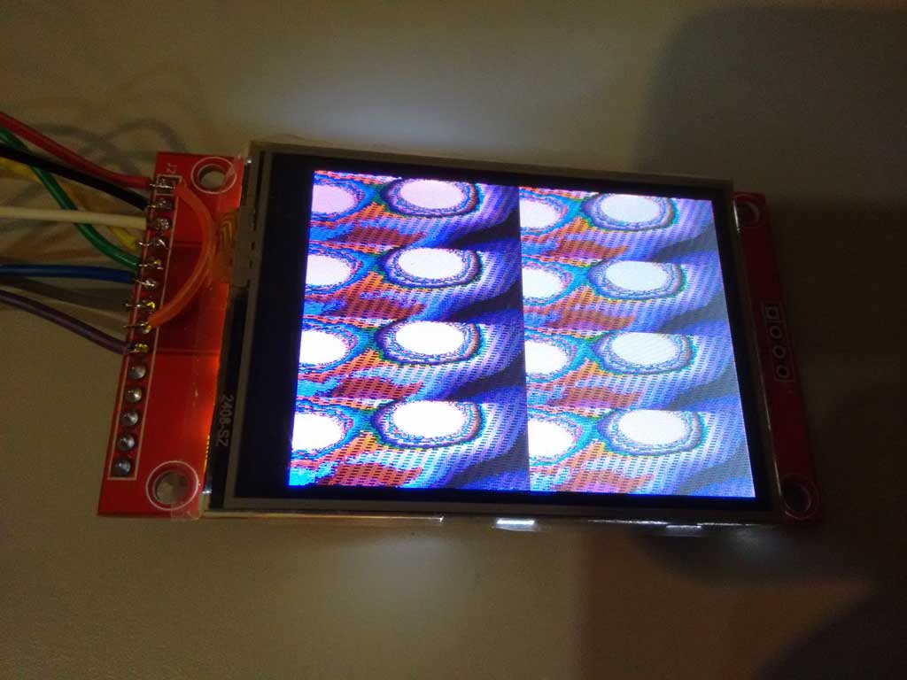
- ov7670_ili9341.jpg (66.14 KiB) Viewed 769 times
The display code seems to have NOPs in it, which I find really strange.
And when I try to just use SPI.dmaSend() to put the line buffer from the camera to the LCD, adding code to the function before it calls dmaSend() causes the image to get displayed differently
This is possibly why the compile option -O2 may be needed, but probably doesnt help me to get it working with the ILI9341
As the camera is set to run as QQVGA, and the display is QVGA, I tried changing the camera code to do QVGA 320×240, by duplicating the BufferedCameraOV7670_QQVGA class to make BufferedCameraOV7670_QVGA (and changed the values)
But if I try to send the pixel buffer to the display it seem to crash the code.
Looking at the maths of the data rates. The code is reading in data at 8 M bytes per sec (from the 8Mhz pixel clock as its 8 bits wide)
But it can only get sent to the display at 36Mhz, plus the overhead of the SPI setup.
So the only way I can see this working is using different lines from each frame.
i.e camera frame 1 use line 1 and send to the display, then wait for the next camera frame, and read only line 2 and send that to the display
But this results in a really low frame rate.
So perhaps some more complex scheme would work, e.g. read every 4th camera line and send it to the display and then offset by 1 line each frame % 4
It was used with retrobsd as swap and ramdisk. The max rd/wr speeds around 10MB/sec. Maybe useful as a frame buffer??
I also have the type of OV7670 which has the FIFO buffer chip on the back. Averlogic AL422B-PBF
http://www.frc.ri.cmu.edu/projects/buzz … Sheets.pdf
As far as I can tell, it should be possible to write one frame from the camera, at 8Mhz, but then switch the clock down to 1Mhz to read the data from the FIFO
Or if that does not work, then just read the frame out line by line, i.e 1 line per frame, though this would be a lot slower
But I hoped to be able to get a full QVGA 320x 240 image onto the ILI9341
However at the moment the colours are all wrong, and I don’t know if the camera is being initialised correctly or not.
The code seems to init the camera and report that its OK, its possible that its not really initialised completely correctly
I think the only way I can test this correctly is to order a ST7735 module from eBay
perhaps this module
http://www.ebay.com.au/itm/1-8-inch-1-8 … 2456943464
And then compile and run the code using this display and confirm its all working OK.
And then try to get the ILI9341 display working
PS. Debugging is a pain. it calls “no interrupts” so USB stops. And also debugging realtime stuff like this is tricky if it relies on bizarre timings.
I will probably have to debug by sending data to Serial port
I may take a look at using daniel’s STM32Generic and the STM DMA library, to perhaps try DMA’ing the GPIO into RAM rather than using the code full of NOPs
[konczakp – Wed Jun 21, 2017 11:51 am] –
That’s right, they differ but it is easy to change in the code how the screen is being initialized. There is something like init screen with blacktab greentab etc.
Ok.
I ordered two of those displays for testing
BTW. If you compile without the -O2 option, can you tell me if it still does not work if you using the latest version of the repo ?
At the moment I get completely wrong colours, which can be associated with the camera not being setup correctly, but could be a by-product of the data not being clocked in correctly from the camera because of timing issues
void initLiveOV7670() {

bool cameraInitialized = camera.init();

tft.initR(INITR_BLACKTAB);

if (cameraInitialized) {

tft.fillScreen(ST7735_BLACK);

} else {

tft.fillScreen(ST7735_RED);

delay(3000);

}
I know why I get 4 images on the screen. Thats because the camera is recording at QQVGA and the screen is QVGA
I tried changing the code to get the camera to record as QVGA (320×240) but when I try to send that data to the ILI9341 it crashes and I’m not sure why
I’ll try recompiling with the -O2 optimisation.
I’ll also need to look at the code to understand how its supposed to work, as the function to write the pixels to the screen is very very slow and I don’t understand why there are NOPs in it
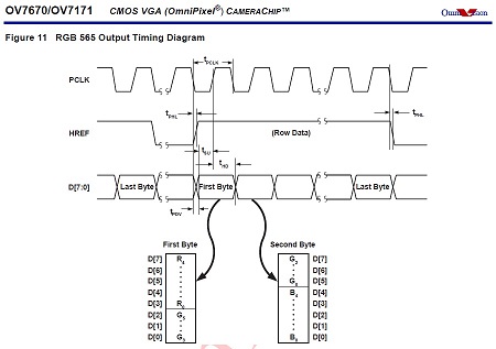
Pixels from the camera are sent in two byte RGB565 format.
first byte:

R - PB15

R - PB14

R - PB13

R - PB12

R - PB11

G - PB10

G - PB09

G - PB08

second byte:

G - PB15

G - PB14

G - PB13

B - PB12

B - PB11

B - PB10

B - PB09

B - PB08
https://cdn-shop.adafruit.com/datasheets/ILI9341.pdf
I think the data format is on page 45
I thought its was 565 like the camera but I’ll need to double check
If you store it as an uint16_t, and write it to the display in little endian, then the colors will be of course different.
[stevestrong – Thu Jun 22, 2017 11:45 am] –
It seems to be 565, but read out in big endian format (high byte first).
If you store it as an uint16_t, and write it to the display in little endian, then the colors will be of course different.
I actually tried building a buffer and byte swapping, but it seemed to make things worse.
The ILI9341 also seems to have an ENDIAN selection, (page 192 of the doc)
So it may be possible to swap it so that its the same as the camera
And if that doesnt fix the colours, I will wait for the 7735 display to arrive, because it will be a lot easier to get it working with the ILI9341, when I know for sure the camera is outputting RGB .
Also, if I byteswap I do get better colours, but it looks like there is something strange going on with either the image capture or sending the data to the display.
Because the byte order seems to be swapping alternately between lines
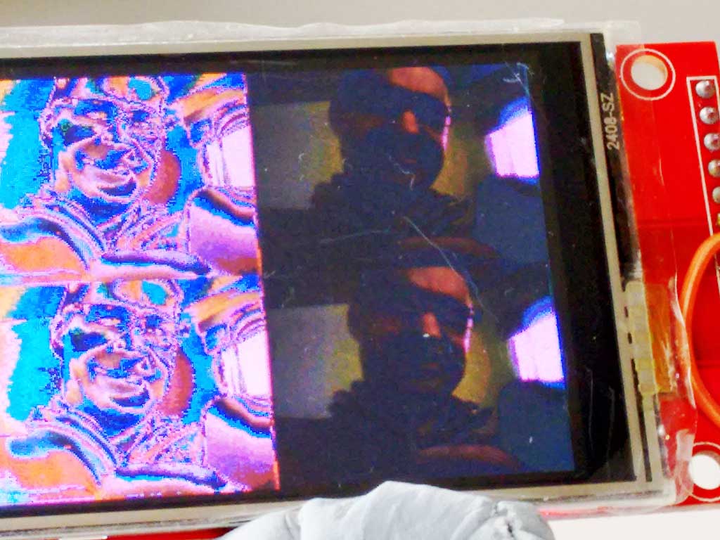
- ov7670_byteswap.jpg (91.22 KiB) Viewed 335 times
I change my code, so that I byte swap and duplicate the pixels down the line, and also send the same line to the display twice
uint8_t dispBuf[320*2];

uint8_t b1;

uint8_t *tdBufEnd = dispBuf + 320*2;
void sendLineToDisplay()
{
// if (screenLineIndex-- > 0)
{
uint8_t *cBufPtr = (uint8_t *)camera.getPixelBuffer();
uint8_t *tdBuf = dispBuf;
while(tdBuf < tdBufEnd)
{
b1=*cBufPtr++;
*tdBuf++=*cBufPtr;
*tdBuf++=b1;
*tdBuf++=*cBufPtr++;
*tdBuf++=b1;
}
SPI.dmaSendAsync((uint8_t *)dispBuf,camera.getPixelBufferLength());
SPI.dmaSendAsync((uint8_t *)dispBuf,camera.getPixelBufferLength());
}
}
[konczakp – Sat Jun 24, 2017 6:53 am] –
With this artifacts (violet or whatever and strange colors) problem I think You could solve that with setting in the main file in setup all data pins to Input mode. It seems that one data pin is not functioning as it should. Try it.
OK
I could have a dry joint , bad connection
I’ll write some test code to read the PB IDR and see if one of the bits is always zero
[stevestrong – Sat Jun 24, 2017 7:07 am] –
Having the need to change the byte swap would mean that you are actually loosing a byte (half pixel) from one line to the next, which you recover somehow at the next line.
I should not be loosing half a pixel
      b1=*cBufPtr++;

*tdBuf++=*cBufPtr++;

*tdBuf++=b1;
However, I think @konczakp may be correct, and that perhaps 1 data it is not connected.
I commented out the line that disabled the interrupts, and used Serial.print to log some data from the camera, and I think bit 3 is always low
e.g.
some data
FA

FB

FA

FB

FB

FB

FB

FB

FB

FB

FB

EB

F9

91

32

D3

52

BA

8B

99

48

91

3

78

83

70

22

78

23

70

3

6B

E2

6B

C1

6B

82

63

82

6B

42

63

42

5B

22

63

22

63

42

6B

63

73

62

73

62

6B

82

73

A2

73

E2

7B

E2

7B

C1

6B

60

6B

41

6B

61

80

29

80

49

78

8

80

28

7B

E9

63

62

6B

29

7B

AA

7B

C9

7B

EA

83

EA

7B

A9

52

C1

42

23

0

C2

10

A2

10

82

10

82

10

82

10

82

10

82

10

82

10

82

8

82

8

82

10

82

10

A2

10

A3

10

A3

10

83

10

83

8

62

8

62

8

82

8

82

10

82

10

82

8

83

8

83

8

82

8

82

8

82

8

82

8

83

8

83

8

82

8

82

8

82

8

82

8

82

8

82

8

82

8

62

8

62

8

62

8

62

8

62

8

62

8

62

8

62

10

C3

11

1

10

E0

8

C0

0

FA

FB

FA

FB

FB

FB

FB

FB

FB

FB

FB

D2

F9

A9

B0

99

CB

99

AA

91

4A

91

4A

89

4A

89

4A

89

9

89

9

88

E9

88

E9

80

C9

80

C9

80

A9

80

A9

88

A9

80

A9

80

A8

80

A8

80

89

88

89

88

89

80

88

80

68

80

43

80

48

80

28

80

43

80

48

88

A9

90

C9

78

8

80

28

78

A

6B

63

63

3

7B

A9

73

C9

7B

CA

7B

C9

73

A9

52

C1

42

23

0

8

82

8

82

8

62

8

62

8

62

8

62

8

62

8

62

8

62

8

62

8

62

8
srp
Anyway
PB10 does not seem to default to input (not sure why)
So I was loosing 1 bit of input data as it was always zero
I added some extra (missing) init code
const int inputPins[]={PB9,PB9,PB10,PB11,PB12,PB13,PB14,PB15};
for(int i=0;i<8;i++)
{
pinMode(inputPins,INPUT);
}
Still a bit washed out but its working a lot better
May be even better in daylight, so I’ll make another video tomorrow
@konczakp thanks again
I should probably do a PR to the authors github account or at least do an issue with this fix !
[Pito – Sat Jun 24, 2017 7:19 pm] –
PB10 on BP issue – http://www.stm32duino.com/viewtopic.php … =30#p30136
Thanks
I vaguely recalled reading that.
I’m sure it can be fixed with some #ifdef statements
[RogerClark – Sat Jun 24, 2017 11:04 pm] –[Pito – Sat Jun 24, 2017 7:19 pm] –
PB10 on BP issue – http://www.stm32duino.com/viewtopic.php … =30#p30136Looks like the best solution is to define
#define BOARD_USB_DISC_DEV        NULL

#define BOARD_USB_DISC_BIT        NULL
[RogerClark – Sun Jun 25, 2017 3:03 am] –
I”ve pushed a commit to fix this for the BP and a few other boards; however some boards seem to have other pins defined as the Disconnect pin, (not just the maple mini) so I’ve left those untouched in case people are using boards with disconnect hardware
Would this affect in any way the USB re-enumeration after reset on non-MM boards?
As far as I can see this pin is exactly what is supposed to do, and if you set to NULL it will not be done anymore.
But I am most probably wrong.
So for boards without extra usb hardware, this pin should not be set to OUTPUT during the USB enable function.
But I think perhaps on boards like the BP, so other code may be needed in USB enable() , but the code was put into USB serial by mistake, because at the time the only type of USB interface supported was USB serial
Please explain me what is going on there, I simply don’t understand it.
First of all, does the CPU use SYSCLK?
Does the CPU run with 72MHz?
If i check the RM0008 figure 8 Clock tree, I see the source for SYSCLK can be HSI, PLLCLK or HSE.
HSI = 8MHz.
HSE = 8MHz (on BP).
PLLCLK = ???
Is the source of SYSCLK set to PLLCLK?
Does this mean that PLLCLK is also 72MHz?
OTOH, MCO is outputting PLLCLK/2 which is in any case half the CPU clock, right?
Does this mean, MCO is outputting 36MHz? Pixel clock = 36MHz?
Anyway, if the CPU clock is only twice the pixel clock, then I don understand those lots of NOPs. They most probably serve a precise timing for sampling the camera data, but it seems that the CPU should sample at each second clock a byte, and not wait with several NOPs.
On the other side, if MCO = 8MHz, this means SYSCLK = 16MHz, SPI clock = 8MHz…
Where am I wrong?
EDIT
I think I got it.
I mixed up XCLK with PCLK.
So it seems that XCLK = 36MHz (MCO), but PCLK = 8MHz (or eventually 9MHz), right?
Did you measure it with the scope?
Anyway, we need those NOPs for an optimum reading of the pixel data at mid of the PCLK high period.
But if there is sooooo much time to wait, why not reading the data and outputting to the display right away?
Re: Reading and writing at the same time.
It would be more efficient to byte swap as it reads the pixels, and also to pixel duplicate, and perhaps even to duplicate the line into a buffer.
This would leave more time for done other processing, but on a F103 or most STM32’s its not going to be possible to do much processing apart from perhaps colour correction, because normally to do things like sharpening etc you need a video frame buffer so that adjacent pixels in X and Y directions can be accessed.
I don’t know what applications there are for just streaming the video to the display, apart from using that as a preview before capturing one frame as a still image.
I suppose it could be used for motion detection by some sort of checksum for each frame (it would be a really bit number), possibly beyond 32 bits.
I checked, and XCLK is is showing as 33mhz on my analyser but it must mean 36Mhz (72Mhz /2)
Pixel clock seems to be 2.25Mhz i.e DIV16 of 36Mhz @ 12 FPS
If I change the framerate, to 7.2 FPS, the Pixel clock changes to 1.51 Mhz (I presume this is 36Mhz DIV24 )
Back on 12 FPS QQVGA
There is a huge amount of time between the VSYNC and the start of the first line of about 3.5 mS
The Pixel clock goes low at the same time as the HREF goes high, and I think the fist pixel of data gets clocked on the next rising edge of the Pixel clock
Each line at QQVGA lasts about 143uS, and there is then a bit gap before the next line , of about 550uS
What would be great, if we could use the DMA to read GPIO port B. On the rising edge of the pixel clock
But on the Blue Pill the pixel data is read in via PB8 to PB15 (upper 8 bits) but the lower 8 bits would be better, but this would need a connection to Boot1 (PB2)
But can we trigger DMA on an (rising/fallig) edge of an input signal (PCLK)?
I think we could count the input signal edge with a timer set up in slave trigger mode, which timer output can then work as DMA trigger source, as I mentioned already here: http://www.stm32duino.com/viewtopic.php?f=19&t=4#p11307
[stevestrong – Mon Jun 26, 2017 9:07 am] –But can we trigger DMA on an (rising/fallig) edge of an input signal (PCLK)?
I think we could count the input signal edge with a timer set up in slave trigger mode, which timer output can then work as DMA trigger source, as I mentioned already here: http://www.stm32duino.com/viewtopic.php?f=19&t=4#p11307
Yes. I thought it was possible to basically trigger a single DMA transfer on EXTI via a Timer, but it sounds difficult to setup
I will test the software when those modules arrive.
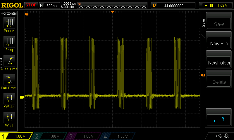
There was a question earlier of why I have “asm volatile(“nop”);” in the method that sends pixels to the screen.
The reason is that SPI.transfer(byte); is terribly slow and it just waists time:
But when I just set the SPI TX register and wait a little before setting the next byte it looks like this
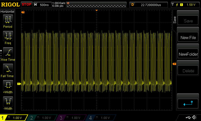
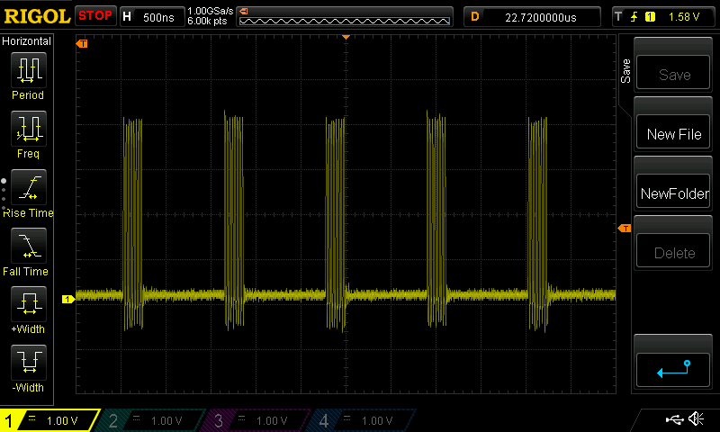
There was also some talk about gaps between lines. Here is how scan lines look like with QQVGA@12Hz:
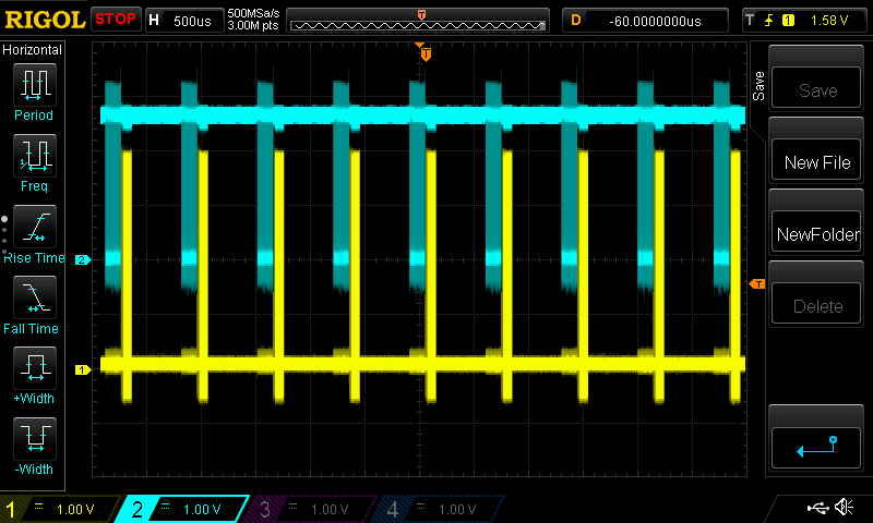
Blue is pixel clock from camera.
Yellow is SPI clock to the screen.
In the Arduino UNO code I was able to get the 10fps because it was in perfect sync with the camera. I could detect the first falling edge of the pixel clock and then read rest of the line blindly without checking the pixel clock. For some reason I was not able to do that with STM32. I believe that QQVGA@30Hz should be possible with STM32 if I could get pixel reading perfectly synchronized.
Thanks for the info.
Indeed, calling spi transfer for each byte in part is not a good idea.
But we have efficient spi multi-byte write routines, with and without dma.
So you could use SPI.write(buffer, nr_bytes); instead of calling SPI.transfer many times consecutively.
According to your scope plot, I assume that keeping the actual sw structure it would be possible to double the fps without changing anything else than the pclk prescaler of the camera. The time period between the spi write train and the next pclk train is large enough.
Thanks for posting.
Perhaps I should have put a link to this thread in my reply to your youtube post.
i am using the ILI9341 display which is QVGA, and also the byte order of the data is reversed from what the camera sends
I do a bit if a hack, by simply transferring the entire pixel buffer from the camera to the display, via a temporary buffer, using the dmaSend() function.
To get from QQVGA to QVGA i pixel byte swap and duplicate pixels from the pixel buffer into my temp buffer, then send the same line twice.
I tried switching to QVGA from the camera but at 12FPS I cant send to the display fast enough, because there is not enough data rate as the SPI max speed is 36M bits per second, but the camera data rate at QVGA is higher.
But I think 7.2 FPS QVGA is technically possible.
@pito also suggested changjng the main PLL to give 80Mhz then SPI to the ILI9341 would be 40MHz, but even with this, I am not sure QVGA at 12 FPS would be possible.
I may move the data input to PB0 to PB7 ( this needs a connection to the Boot1 header but this is OK)
Then it should be possible to clock the data from the camera via DMA.
https://cdn-shop.adafruit.com/datasheets/ILI9341.pdf
[Pito – Tue Jun 27, 2017 5:51 am] –
Btw the Ili9341 datasheet says the “write” SPI clock shall be 10MHz max..
https://cdn-shop.adafruit.com/datasheets/ILI9341.pdf
LOL
We already run it at 36Mhz ![]()
I think for playing with video and your intention to make some image processing the Black F407ZET plus 512-1024kB external sram is a minimum. F407 even possess the DCMI..
[Pito – Tue Jun 27, 2017 6:26 am] – F407 even possess the DCMI..
That sounds like an easy job.
But where is the challenge then? ![]()
[stevestrong – Mon Jun 26, 2017 7:52 pm] –
@indrekluuk,
Thanks for the info.
Indeed, calling spi transfer for each byte in part is not a good idea.
But we have efficient spi multi-byte write routines, with and without dma.
So you could use SPI.write(buffer, nr_bytes); instead of calling SPI.transfer many times consecutively.
I tested. SPI.write(const uint8 *data, uint32 length) is only marginally better than calling SPI.transfer one by one.
In this case you could use:
SPI.write(uint8 data);void sendLineToDisplay() {
if (screenLineIndex > 0) {
screenLineStart();
SPI.write(camera.getPixelBuffer(), camera.getPixelBufferLength());
screenLineEnd();
}
}I don’t have QVGA screen, but I was able to display quarter of the image clearly on my smaller screen.
I use dmaSend() a whole line at a time
Edit.
I have QVGA
I will download later
Sorry, it seems that this is bit reversal and I already have a method for that.
RogerClark, I just checked OV7670 datasheet (https://www.voti.nl/docs/OV7670.pdf)
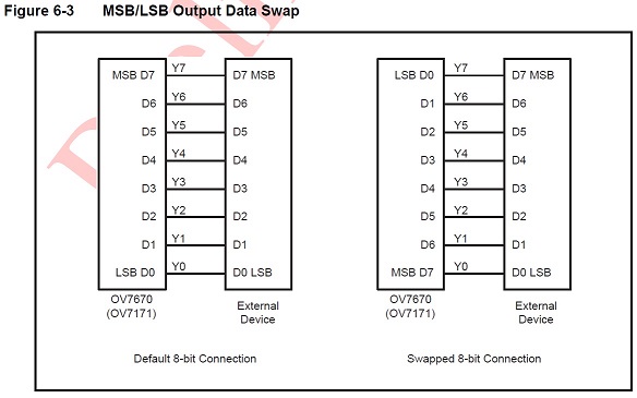
OV7670 has a register bit that swaps pixel bytes:
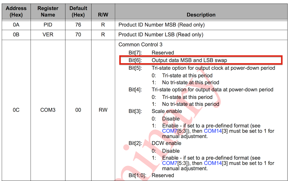
You don’t have to write any hacks to swap byte order. I will add a method to the CameraOV7670 class that sets this register bit when I get back home in the evening.
I did look in the spec for the camera, but it described the bytes as “odd” and “Even” and I could not find any other functions which said they changed this or the byte order.
This will save a lot of processing, and definitely help with data rate.
But I think 7.2FPS at QVGA is as fast as technically possible, because the data rate to the ILI9341 display, even when overclocked to 36Mhz (Mbps) is slower than QVGA from the camera at 12 FPS
- OV7670 data swap.jpg (46.34 KiB) Viewed 269 times
can you please tell us which SPI driver are you using? Is it from the official Arduino_STM32 repository?
https://github.com/rogerclarkmelbourne/ … es/SPI/src
https://github.com/rogerclarkmelbourne/ … /spi.c#L95
Because this should preform much better than what you have measured.
If I use the “SPI.write(buf, nr_bytes)” function, the SPI clock is almost continuous.
I am using platformIO for compiling and uploading.
At quick glance it seems that the SPI library that comes with platformIO is this:
https://github.com/rogerclarkmelbourne/ … es/SPI/src
[indrekluuk – Wed Jun 28, 2017 8:23 pm] –
@stevestrongI am using platformIO for compiling and uploading.
At quick glance it seems that the SPI library that comes with platformIO is this:
https://github.com/rogerclarkmelbourne/ … es/SPI/src
I am using the ILI9341, and the benefit of this, appears to be that I can dma whole lines via SPI.
At the moment I have to byte swap after the pixel buffer is complete, but it would be easy to change the code that capture the pixels from the camera, so that it performs the byte swap as the data is put into the buffer.
( I may need to change the number of NOPs if this slows down the code a bit, but there are plenty of NOPs, so there would be some to do some pointer arithmetic and it’s possible that the ARM instruction set has methods to do *(ptr + 1) )
I dont know, would it help if you set the spi to 16 bit transfer mode? Would the bytes change their order this way?
[stevestrong – Wed Jun 28, 2017 10:08 pm] –
As far as i know, @indrekluuk uses the trick that ignores the very first byte so that the high byte of the next pixel will be the high byte of the actual pixel.I dont know, would it help if you set the spi to 16 bit transfer mode? Would the bytes change their order this way?
I thought about that trick, but I don’t think it works does it ?
Don’t you end up with the high byte of pixel1 and the low byte of pixel 2, being seen as the first byte sent to the display.
If this is what I think you’re saying, then there is a big problem becuase the Green colour channel is split across the bottom of one byte and the top of the next bye, so the green channel for the resultant pixel is a mix of 2 bytes, and could be totally wrong, if the value changes very much from pixel to pixel e.g. goes over the threshold where the two halfs of the green channel is split across the bytes.
[RogerClark – Wed Jun 28, 2017 11:32 pm] –
Don’t you end up with the high byte of pixel1 and the low byte of pixel 2, being seen as the first byte sent to the display.
Exactly, this is the trick, if I interpret correctly the stuff here: https://github.com/indrekluuk/LiveOV767 … 7670.h#L17
The issue with green color I don think is critical since the upper 3 bits are from the correct pixel, the lower 3 bits do not have big influence on the color when combined with red and blue channel.
The only thing is the last half pixel, which is neglected, I think. But it is on the margin so is not disturbing if it does not have the right color.
[stevestrong – Wed Jun 28, 2017 10:08 pm] –
As far as i know, @indrekluuk uses the trick that ignores the very first byte so that the high byte of the next pixel will be the high byte of the actual pixel.
You are correct. Currently I “fix” the missing first byte by adding a 0 byte at the beginning. This means that the very first pixel is broken.
This is because there isn’t enough time to detect the pixel clock edge and read the pixel in higher FPS. Maybe if you could do the pixel read in hardware level (I assume this is what DMA does?) then the problem would be fixed.
Now I saw that the spec has “Dummy pixel insert MSB” and “Dummy pixel insert LSB”. It is probably possible to fix the first byte issue by adding a dummy byte in the beginning that will be ignored.
Aren’t there loads of nops in the code ?
[stevestrong – Thu Jun 29, 2017 6:33 am] –[RogerClark – Wed Jun 28, 2017 11:32 pm] –
Don’t you end up with the high byte of pixel1 and the low byte of pixel 2, being seen as the first byte sent to the display.Exactly, this is the trick, if I interpret correctly the stuff here: https://github.com/indrekluuk/LiveOV767 … 7670.h#L17
The issue with green color I don think is critical since the upper 3 bits are from the correct pixel, the lower 3 bits do not have big influence on the color when combined with red and blue channel.
The only thing is the last half pixel, which is neglected, I think. But it is on the margin so is not disturbing if it does not have the right color.
Just to clarify. Currently in the code the pixels are paired correctly. Padding in the buffer is added since I miss the fist pixel byte when reading from camera. Meaning I am not paring high byte of pixels 1 and low byte of pixel 2.
If the pairing of the pixel bytes are shifted then the image looks a little fuzzy.
I think @stevestong was implying that you swap endian ness that way, with the resultant problem in the green channel
[RogerClark – Thu Jun 29, 2017 6:45 am] –
There is plenty of time to byte swap correctly.Aren’t there loads of nops in the code ?
I have to think about it a little (Perhaps in the weekend).
I think it is possible to get free byte swap if the memory structure is defined correctly. Since pixelBuffer is in static memory +1 -1 calculations with buffer address will be done in compile time.
Something like this:
while (bufferIndex < (getPixelBufferLength() / 2)) {

waitForPixelClockLow();

asm volatile("nop");

pixelBuffer.writeBuffer[bufferIndex++].highByte = readPixelByte();
waitForPixelClockLow();
asm volatile("nop");
pixelBuffer.writeBuffer[bufferIndex++].lowByte = readPixelByte();
}
After consulting both OV7670 and ILI9341 manuals I see that there is no need to swap the bytes.
OV7670 data output begins with the r+(g/2) byte:
- OV7670 data output.jpg (33.53 KiB) Viewed 276 times
If you are using “camera.getPixelByte(i)” or “camera.getPixelBuffer()” then it should be in the correct order.
Here is how I understand the pixel data to be. It seems that the spec is not 100% correct on that.
1. For VGA resolution (without any downsampling) the byte order from the camera is
LOW_0, HIGH_0, LOW_1, HIGH_1, … LOW_639, HIGH_639
I had to swap bytes to get correct colors
2. For downsampled resolution (QVGA and QQVGA) the byte order switched around and first and last pixel are broken.
(HIGH_0 is missing), LOW_0, HIGH_1, LOW_1, … HIGH_159, LOW_159, HIGH_160 (<- extra half pixel)
To get correct colors I either have to add extra byte in the beginning (drop the last half pixel) or in the end (drop the fist half pixel).
If someone can prove me wrong I am happy to test it myself again.
[indrekluuk – Thu Jun 29, 2017 10:53 am] –
@RogerClark, do you have your code somewhere in Github? If it is as @stevestrong says that ILI9341 has the same byte order then the question is why do you need swapping.If you are using “camera.getPixelByte(i)” or “camera.getPixelBuffer()” then it should be in the correct order.
My code is a hack, but I will zip and email it to you, ( as I am admin, I can look up your email address you register with)
PS. I don’t allow attachments in PMs as it eats to much disk space, and there are other problems with that
Camera was running an QQVGA ( I didnt modify anything)
In main.cpp
Remove the stuff about the 7735 display and add the code for the ILI9341 display
#include "SPI.h"
#include <Adafruit_GFX_AS.h> // Core graphics library, with extra fonts.
#include <Adafruit_ILI9341_STM.h> // STM32 DMA Hardware-specific library
#define TFT_CS PA2
#define TFT_DC PA0
#define TFT_RST PA1
Adafruit_ILI9341_STM tft = Adafruit_ILI9341_STM(TFT_CS, TFT_DC, TFT_RST); // Use hardware SPI
I ordered this from eBay:
http://www.ebay.com/itm/2-4-SPI-TFT-LCD … 2749.l2649
It takes a couple of weeks to reach me. Then I can try it myself.
Could you send the whole project? Then I can add ILI9341 support to my Github repo after I get it working.
Did you try the QVGA version?
[indrekluuk – Sat Jul 01, 2017 6:30 am] –
I ordered this from eBay:
http://www.ebay.com/itm/2-4-SPI-TFT-LCD … 2749.l2649
I ordered exactly the same LCD form the same seller couple of days ago. Let’s see if we get the same on-board controller ![]()
[indrekluuk – Sat Jul 01, 2017 6:30 am] –
This is a little strange. To me it seems that you shouldn’t need byte swapping.I ordered this from eBay:
http://www.ebay.com/itm/2-4-SPI-TFT-LCD … 2749.l2649
It takes a couple of weeks to reach me. Then I can try it myself.Could you send the whole project? Then I can add ILI9341 support to my Github repo after I get it working.
Did you try the QVGA version?
Sorry. I’ve not had time to try it yet.
#include <SPI.h>

#include <SD.h>
File myFile;
void setup() {
SPI.setModule(1);
Serial.begin(115200);
delay(4000);
Serial.print("Initializing SD card...");
if (!SD.begin(PA4)) {
Serial.println("initialization failed!");
return;
}
Serial.println("initialization done.");
if (SD.remove("programs.txt")) {
Serial.println("Removing old file");
} else {
Serial.println("Nothing to remove");
}
// open the file. note that only one file can be open at a time,
// so you have to close this one before opening another.
myFile = SD.open("programs.txt", FILE_WRITE);
// if the file opened okay, write to it:
if (myFile) {
Serial.print("Writing to file...");
myFile.println("testing 1, 2, 3.");
// close the file:
myFile.close();
Serial.println("done.");
} else {
// if the file didn't open, print an error:
Serial.println("error opening file");
}
// re-open the file for reading:
myFile = SD.open("programs.txt");
if (myFile) {
Serial.print("Opening file : ");
// read from the file until there's nothing else in it:
while (myFile.available()) {
Serial.write(myFile.read());
}
// close the file:
myFile.close();
} else {
// if the file didn't open, print an error:
Serial.println("error opening file");
}
}
void loop() {
// nothing happens after setup
}
PB3 and PB4 must be enabled, otherwise they are used for swd/jtag/debug.
Why sd.begin with PA4?
disableDebugPorts();sorry, but I think your issue is not related to this topic (see title).
Could you please open another thread in another thread group (for example, here: http://www.stm32duino.com/viewforum.php?f=9)?
thanks.
For me it is not understandable why screen with SPI uses different pins then normal SPI pins (they are free). For example normal MISO pin is on pin PA6 but for the screen was used PA3. Same situation is with SS pin.
I do not understand your issue.. You may connect the tft to SPI1 and the sdcard to SPI2, or vice versa. You may use any pin for the card’s CS, and also for tft’s CS you may use any pin you want..
With MM/BP when using SPI1 only you may try
TFT CS     - PA2

TFT MISO   - PA6 - MISO SD

TFT SCK    - PA5 - SCK SD

TFT MOSI   - PA7 - MOSI SD

- PA3 - CS SDFor CS pins you can select any of the remaining, also PA4 (I am using it as well in my projects) or any other PA0..PA3.
But don’t forget to set the mode as OUTPUT for the CS pins! (I don’t see that in your code…)
pinMode(SD_CS, OUTPUT);
Again, when using single SPI for both you must guarantee your code will not access both tft and sdcard at the same moment (the CS_card and CS_tft cannot be low at the same time).
srp
TFT CS(SS)    - PA2

TFT A0(MISO)  - PA3

TFT SCK       - PA5 - SCK SD

- PA6 - MISO SD

TFT SDA(MOSI) - PA7 - MOSI SD

- PB3 - CS(SS) SD
PA2 & PB3 both need the lines to set them as outputs and to set both high initially.
stephen
Use SdFat, for example:
#include "SPI.h"

#include "SdFat.h"

const uint8_t chipSelect = PA3;

SdFat sd;

SdFile file;

void setup() {

delay(3000);

Serial.begin(115200);

if (!sd.begin(chipSelect, SD_SCK_MHZ(18))) {

Serial.println("INIT ERROR");

sd.initErrorHalt();  // prints out sdfat's error codes

} else {

Serial.println("INIT OK");

}

delay(500);

}

void loop() {

}i’ve just deleted my post about you meaning pb3 not pa3, btdtgt
stephen
The workaround is to issue a dummy 8bit SPI transaction after the CS goes High (after the sdcard is deselected).
When hanging an Sdcard and a TFT on the same SPI bus this may cause an issue.
But I think it has been fixed at least in Sdfat already..
And this is not good for SdFat…
You could remove “noInterrupts();” from the init method and disable them only temporarily during line read:
noInterrupts();
camera.readLine();
interrupts();
now my main.cpp looks like:
#include "main.h"

#include "Arduino.h"

#include "src/camera/buffered/BufferedCameraOV7670.h"

#include "src/camera/buffered/stm32_72mhz/BufferedCameraOV7670_QQVGA_30hz.h"

#include "src/camera/buffered/stm32_72mhz/BufferedCameraOV7670_QQVGA.h"

#include <Adafruit_ILI9341_STM.h> // STM32 DMA Hardware-specific library

#include <SD.h>
File myFile;
#define TFT_CS PA2
#define TFT_DC PA0
#define TFT_RST PA1
BufferedCameraOV7670_QQVGA camera(CameraOV7670::PIXEL_RGB565, BufferedCameraOV7670_QQVGA::FPS_15_Hz);
//BufferedCameraOV7670_QQVGA_30hz camera(CameraOV7670::PIXEL_RGB565);
//BufferedCameraOV7670<uint16_t, 320, uint8_t, 160, uint8_t, 120> camera(
// CameraOV7670::RESOLUTION_QQVGA_160x120,
// CameraOV7670::PIXEL_RGB565,
// 4);
Adafruit_ILI9341_STM tft = Adafruit_ILI9341_STM(TFT_CS, TFT_DC, TFT_RST); // Use hardware SPI
void initLiveOV7670()
{
// Serial.begin();
pinMode(PC13,OUTPUT);// flashing frame LED
pinMode(PB10, INPUT);
tft.begin();
tft.setRotation(3);
bool cameraInitialized = camera.init();
if (cameraInitialized) {
tft.fillScreen(ILI9341_BLACK);
} else {
tft.fillScreen(ILI9341_RED);
while(1);
}
// noInterrupts();
}
inline void sendLineToDisplay() __attribute__((always_inline));
//inline void screenLineStart(void) __attribute__((always_inline));
//inline void screenLineEnd(void) __attribute__((always_inline));
inline void sendPixelByte(uint8_t byte) __attribute__((always_inline));
inline void pixelSendingDelay() __attribute__((always_inline));
//static const uint16_t lineLength = 320;
//static const uint16_t lineCount = 240;
// Normally it is a portrait screen. Use it as landscape
//uint8_t screen_w = 320;
uint8_t screen_h = 240;
uint8_t screenLineIndex;
// this is called in Arduino loop() function
void processFrame() {
screenLineIndex = screen_h;
digitalWrite(PC13,!digitalRead(PC13));
String strser = "";
while (Serial.available () > 0) {
strser += char(Serial.read ());
}
if (strser != ""){
if (strser.startsWith("test")){ // Wyślij pakiet testowy przez nrf24l01 oraz zrób test karty sd
tft.fillScreen(ILI9341_WHITE);
pinMode(PA2, OUTPUT);
pinMode(PB3, OUTPUT);
digitalWrite(PA2, HIGH);
digitalWrite(PB3, LOW);
frame_sd();
digitalWrite(PA2, LOW);
digitalWrite(PB3, HIGH);
tft.begin();
tft.setRotation(3);
tft.fillScreen(ILI9341_WHITE);
}
}
camera.waitForVsync();
noInterrupts();
for (uint8_t i = 0; i < camera.getLineCount(); i++) {
camera.readLine();
sendLineToDisplay();
}
interrupts();
}
uint8_t dispBuf[320*2];
uint8_t b1;
uint8_t *tdBufEnd = dispBuf + 320*2;
void sendLineToDisplay()
{
uint8_t *cBufPtr = (uint8_t *)camera.getPixelBuffer();
uint8_t *tdBuf = dispBuf;
// pixel duplicate and byte swap
while(tdBuf < tdBufEnd)
{
b1=*cBufPtr++;
*tdBuf++=*cBufPtr;
*tdBuf++=b1;
*tdBuf++=*cBufPtr++;
*tdBuf++=b1;
}
//send the same line twice
// Note. SPI.dmaSendAsync() is also OK and probably better, but I went back to the blocking version last time I was testing things
SPI.dmaSend((uint8_t *)dispBuf,camera.getPixelBufferLength());
SPI.dmaSend((uint8_t *)dispBuf,camera.getPixelBufferLength());
}
void init_sd(void){
SPI.setModule(1);
Serial.print("Initializing SD card...");
if (!SD.begin(PB3)) {
Serial.println("initialization failed!");
return;
}
Serial.println("initialization done.");
}
void check_sd(void){
if (SD.remove("programs.txt")) {
Serial.println("Removing old file");
} else {
Serial.println("Nothing to remove");
}
// open the file. note that only one file can be open at a time,
// so you have to close this one before opening another.
myFile = SD.open("programs.txt", FILE_WRITE);
// if the file opened okay, write to it:
if (myFile) {
Serial.print("Writing to file...");
myFile.println("testing 1, 2, 3.");
// close the file:
myFile.close();
Serial.println("done.");
} else {
// if the file didn't open, print an error:
Serial.println("error opening file");
}
// re-open the file for reading:
myFile = SD.open("programs.txt");
if (myFile) {
Serial.print("Opening file : ");
// read from the file until there's nothing else in it:
while (myFile.available()) {
Serial.write(myFile.read());
}
// close the file:
myFile.close();
} else {
// if the file didn't open, print an error:
Serial.println("error opening file");
}
}
CameraOV7670::PixelFormat pixelFormat = CameraOV7670::PIXEL_RGB565;
inline void endOfFrame_sd(void) __attribute__((always_inline));
inline void endOfLine_sd(void) __attribute__((always_inline));
inline void sendNextPixelByte_sd() __attribute__((always_inline));
inline void sendPixelByteH_sd(uint8_t byte) __attribute__((always_inline));
inline void sendPixelByteL_sd(uint8_t byte) __attribute__((always_inline));
static const uint16_t lineLength = 160;
static const uint16_t lineCount = 120;
uint8_t lineBuffer [lineLength*2 + 1 + 5];
uint16_t lineBufferIndex = 0;
void frame_sd(void){
SD.remove("frame");
myFile = SD.open("frame", FILE_WRITE);
if (myFile) {
camera.waitForVsync();
for (uint16_t y = 0; y < lineCount; y++) {
lineBufferIndex = 0;
lineBuffer[0] = 0; // first byte from Camera is half a pixel
for (uint16_t x = 1; x < lineLength*2+1; x+=5) {
// start sending first bytes while reading pixels from camera
sendNextPixelByte_sd();
// we can read 5 bytes from camera while one byte is sent over UART
camera.waitForPixelClockRisingEdge();
lineBuffer[x] = camera.readPixelByte();
camera.waitForPixelClockRisingEdge();
lineBuffer[x+1] = camera.readPixelByte();
camera.waitForPixelClockRisingEdge();
lineBuffer[x+2] = camera.readPixelByte();
camera.waitForPixelClockRisingEdge();
lineBuffer[x+3] = camera.readPixelByte();
camera.waitForPixelClockRisingEdge();
lineBuffer[x+4] = camera.readPixelByte();
}
// send rest of the line
while (lineBufferIndex < lineLength * 2) {
sendNextPixelByte_sd();
}
endOfLine_sd();
}
endOfFrame_sd();
myFile.close();
}
}
void sendNextPixelByte_sd() {
uint8_t byte = lineBuffer[lineBufferIndex];
uint8_t isLowPixelByte = lineBufferIndex & 0x01;
// make pixel color always slightly above 0 since zero is end of line
if (isLowPixelByte) {
sendPixelByteL_sd(byte);
} else {
sendPixelByteH_sd(byte);
}
lineBufferIndex++;
}
void sendPixelByteH_sd(uint8_t byte) {
// RRRRRGGG
myFile.print(byte | 0b00001000);
}
void sendPixelByteL_sd(uint8_t byte) {
// GGGBBBBB
myFile.print(byte | 0b00100001);
}
void endOfFrame_sd() {
// frame width
myFile.print((lineLength >> 8) & 0xFF);
myFile.print(lineLength & 0xFF);
// frame height
myFile.print((lineCount >> 8) & 0xFF);
myFile.print(lineCount & 0xFF);
// pixel format
myFile.print((pixelFormat));
myFile.print(0xFF);
myFile.print(0x00);
myFile.print(0x00);
myFile.print(0x00);
}
void endOfLine_sd() {
myFile.print(0x00);
}
void sendPixelByte(uint8_t byte) {
spi_tx_reg(SPI1, byte);
//SPI.transfer(byte);
// this must be adjusted if sending loop has more/less instructions
asm volatile("nop");
asm volatile("nop");
asm volatile("nop");
asm volatile("nop");
asm volatile("nop");
asm volatile("nop");
asm volatile("nop");
asm volatile("nop");
asm volatile("nop");
}
void pixelSendingDelay() {
asm volatile("nop");
asm volatile("nop");
asm volatile("nop");
asm volatile("nop");
asm volatile("nop");
asm volatile("nop");
asm volatile("nop");
asm volatile("nop");
asm volatile("nop");
asm volatile("nop");
asm volatile("nop");
asm volatile("nop");
asm volatile("nop");
asm volatile("nop");
asm volatile("nop");
asm volatile("nop");
asm volatile("nop");
asm volatile("nop");
}
myFile.print(byte | 0b00001000);
myFile.write(byte);I tried write function but it gives me exactly the same result so the problem is somewhere else.
As far as I know the OV7660 raw images are not RGB values because there is a bayer filter and so the colours are packed differently.
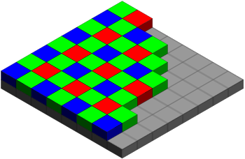
The code used by ComputerNerd uses a converter.
https://github.com/ComputerNerd/RawCame … -converter

- frame 1.png (111.09 KiB) Viewed 355 times
Red:

- R.jpg (8.24 KiB) Viewed 346 times
as it seems that each line is moving right, maybe the length of the line is too long
both are daft ideas of course
stephen

- Clipboard02.jpg (8.01 KiB) Viewed 344 times
Also, I do not understand how you can read the above data from the sdcard file when you are writing it as a binary – it must be a non-readable mess when it is in binary – I see there nice numbers from 0-9 – that is not a binary..
1189173140109771091401652004924571714157491421671069910616720712510810775431071072002252410110
CameraOV7670::PixelFormat pixelFormat = CameraOV7670::PIXEL_RGB565;
inline void endOfFrame_sd(void) __attribute__((always_inline));
inline void endOfLine_sd(void) __attribute__((always_inline));
inline void sendNextPixelByte_sd() __attribute__((always_inline));
inline void sendPixelByteH_sd(uint8_t byte) __attribute__((always_inline));
inline void sendPixelByteL_sd(uint8_t byte) __attribute__((always_inline));
static const uint16_t lineLength = 160;
static const uint16_t lineCount = 120;
uint8_t lineBuffer [lineLength*2 + 1 + 5];
uint16_t lineBufferIndex = 0;
void frame_sd(void){
SD.remove("frame");
myFile = SD.open("frame", FILE_WRITE);
if (myFile) {
camera.waitForVsync();
for (uint16_t y = 0; y < lineCount; y++) {
lineBufferIndex = 0;
lineBuffer[0] = 0; // first byte from Camera is half a pixel
for (uint16_t x = 1; x < lineLength*2+1; x+=5) {
// start sending first bytes while reading pixels from camera
sendNextPixelByte_sd();
// we can read 5 bytes from camera while one byte is sent over UART
camera.waitForPixelClockRisingEdge();
lineBuffer[x] = camera.readPixelByte();
camera.waitForPixelClockRisingEdge();
lineBuffer[x+1] = camera.readPixelByte();
camera.waitForPixelClockRisingEdge();
lineBuffer[x+2] = camera.readPixelByte();
camera.waitForPixelClockRisingEdge();
lineBuffer[x+3] = camera.readPixelByte();
camera.waitForPixelClockRisingEdge();
lineBuffer[x+4] = camera.readPixelByte();
}
// send rest of the line
while (lineBufferIndex < lineLength * 2) {
sendNextPixelByte_sd();
}
endOfLine_sd();
}
endOfFrame_sd();
myFile.close();
}
}
void sendNextPixelByte_sd() {
uint8_t byte = lineBuffer[lineBufferIndex];
uint8_t isLowPixelByte = lineBufferIndex & 0x01;
// make pixel color always slightly above 0 since zero is end of line
if (isLowPixelByte) {
sendPixelByteL_sd(byte);
} else {
sendPixelByteH_sd(byte);
}
lineBufferIndex++;
}
void sendPixelByteH_sd(uint8_t byte) {
// RRRRRGGG
myFile.print(byte | 0b00001000);
}
void sendPixelByteL_sd(uint8_t byte) {
// GGGBBBBB
myFile.print(byte | 0b00100001);
}
void endOfFrame_sd() {
// frame width
myFile.print((lineLength >> 8) & 0xFF);
myFile.print(lineLength & 0xFF);
// frame height
myFile.print((lineCount >> 8) & 0xFF);
myFile.print(lineCount & 0xFF);
// pixel format
myFile.print((pixelFormat));
myFile.print(0xFF);
myFile.print(0x00);
myFile.print(0x00);
myFile.print(0x00);
}
void endOfLine_sd() {
myFile.print(0x00);
}
Prepare the data in a buffer and then use
myFile.write(buf, nr_bytes);that line in the image to me says the line length is short, it should be vertical ??
then you’d have three vertical bands, locate the start of each band and from the start points
possibly combine the three values into ‘something’, pixel, colour code etc
something bugging me, istr something about difference values in relation to video signals ?? red-green ?? red-blue ???
stephen
It should be exactly 120*160*2 = 38400 bytes (2 bytes per pixel in RGB565 format)
Possibly there are also timing issues. If myFile.print is blocking then you probably miss some pixels.
In the UART example sending data over UART was non-blocking. While I was sending one byte over UART I was reading next 5 bytes from the camera.
Maybe it would be better to use the buffered version (not the UART example that reads one pixel at the time). Then after reading a line from camera you could write the line with some kind of buffered write method to the SD card.
When I receive the ILI9341 display I can try it myself also. I can measure with Oscilloscope if there is enough time to write data to SD card.
Maybe You could try it with the smaller screen. This issue is not hardware depended because the smaller screen also have SD slot. You could connect only SD (without screen) and try to run this code once in setup function or in the loop and overwrite the file.
My file is about 100kb if I remember right because I’m at work right now.
That would be difficult as the Sdcards have got the write latencies (see above my post).
Writing a 38kB file onto an sdcard could last between 20msecs to XXXmsecs.
The best way to proceed is to change the board for an F103 with 64KB ram or an F407 and save the 38kB video frame into a buffer.
Or, to save the picture in smaller chunks, such the buffer fits into your F103, and then assemble the files on your PC.
Or, use FreeRtos, and use an FIFO for writing on the sdcard (the producer will be the task reading bytes off the camera module into the FIFO, and the consumer will be the task writing bytes off the FIFO onto the sdcard )..
Write the data data to the display in real time, then read it out a line at a time, and send the line to the SD.
Can someone post the link to the QVGA version, or does https://github.com/indrekluuk/LiveOV7670 now default to QVGA
Or perhaps i need to change something in the latest version from github
https://github.com/indrekluuk/LiveOV767 … 2/main.cpp
Comment out line 35:
BufferedCameraOV7670_QQVGA camera(CameraOV7670::PIXEL_RGB565, BufferedCameraOV7670_QQVGA::FPS_12_Hz);
Remove comments from line 36:
BufferedCameraOV7670_QVGA camera(CameraOV7670::PIXEL_RGB565, BufferedCameraOV7670_QVGA::FPS_7p5_Hz);
OK.
Thats basically what I tried doing myself, but I can’t recall if it worked for me when I reduced the frame rate.
I know it doesnt work at 12fps as the screen is not fast enough to accept QVGA at 12 fps
http://www.stm32duino.com/viewtopic.php … 886#p31867
Perhaps we can add that pragma to the files that need -O2 optimisation, so that it would run ok without changing platform.txt
[RogerClark – Sat Jul 15, 2017 9:06 pm] –
One simple solution to memory to store the image is simply to use the display.Write the data data to the display in real time, then read it out a line at a time, and send the line to the SD.
This is a very good idea! Thanks. I’ve searched over the internet and found some examples and now I’m trying to get it working on STM32 but without any success. It freezes when I’m trying to read the pixel. (I was thinking about reading pixel by pixel when getting the whole image from TFT GRAM) Here is what I did.
In Adafruit_ILI9341_STM.h I added
//Pio *_dcport;

volatile uint8_t *_dcport, *_csport;

uint8_t  _cspinmask, _dcpinmask;
SPISettings _spiSettings;
uint8_t readdata(void),
readcommand8(uint8_t reg, uint8_t index = 0);
// Enables CS
inline __attribute__((always_inline))
void enableCS(){
*_csport &= ~_cspinmask;
}
// Disables CS
inline __attribute__((always_inline))
void disableCS() {
*_csport |= _cspinmask;
}
__attribute__((always_inline))
void spiwrite16(uint16_t d) {
SPI.transfer(highByte(d));
SPI.transfer(lowByte(d));
}
// Writes commands to set the GRAM area where data/pixels will be written
void setAddr_cont(uint16_t x, uint16_t y, uint16_t w, uint16_t h)
__attribute__((always_inline)) {
writecommand_cont(ILI9341_CASET); // Column addr set
setDCForData();
write16_cont(x); // XSTART
write16_cont(x+w-1); // XEND
writecommand_cont(ILI9341_PASET); // Row addr set
setDCForData();
write16_cont(y); // YSTART
write16_cont(y+h-1); // YEND
}
// Sets DC to Data (1)
inline __attribute__((always_inline))
void setDCForData() {
*_dcport |= _dcpinmask;
}
// Sets DC to Command (0)

inline __attribute__((always_inline))

void setDCForCommand(){

*_dcport &= ~_dcpinmask;

}
// Enables CS, sets DC for Command, writes 1 byte
// Does not disable CS
inline __attribute__((always_inline))
void writecommand_cont(uint8_t c) {
setDCForCommand();
enableCS();
write8_cont(c);
}
// Enables CS, sets DC for Data and reads 1 byte
// Does not disable CS
__attribute__((always_inline))
uint8_t readdata8_cont() {
setDCForData();
enableCS();
return read8_cont();
}
// Reads 1 byte
__attribute__((always_inline))
uint8_t read8_cont() {
return SPI.transfer(ILI9341_NOP);
}
__attribute__((always_inline))
uint8_t read8_last() {
uint8_t r = SPI.transfer(ILI9341_NOP);
disableCS();
return r;
}
// Writes 2 bytes
// CS, DC have to be set prior to calling this method
__attribute__((always_inline))
void write16_cont(uint16_t d) {
spiwrite16(d);
}
// writes 1 byte
// CS and DC have to be set prior to calling this method
__attribute__((always_inline))
void write8_cont(uint8_t c){
spiwrite(c);
}
__attribute__((always_inline))
void beginTransaction() {
SPI.beginTransaction(_spiSettings);
}
__attribute__((always_inline))
void endTransaction() {
SPI.endTransaction();
}
FYI.
I’ve added a modified version of @mtiutiu’s optimisation menu to the F1 core.
This means you don’t need to modify your platform.txt to make @ indrekluuk’s liveOV7670 code run, as you can pick the -O2 optimasation from the menu
Actually I’ve found that liveOV7670 runs fine with -O1 optimisation or -O2 or -O3. The only optimisation it doesnt work with, is our current default of -Os (small code size)
// Sets DC to Command (0)
inline __attribute__((always_inline))
void setDCForCommand(){
*_dcport &= ~_dcpinmask;
}
//Pio *_dcport;

volatile uint8_t *_dcport, *_csport;

uint8_t  _cspinmask, _dcpinmask;
#define TFT_CS         PA2

#define TFT_DC         PA0

#define TFT_RST        PA1
Try to code it as this fix value 0x0001.
changing it to
inline __attribute__((always_inline))

void setDCForCommand(){

Serial.println("ok1");

*_dcport = 0x0001;

Serial.println("ok2");

}
The library already has vars for the ports and uses them without any problems e.g.
void Adafruit_ILI9341_STM::writecommand(uint8_t c) {

*dcport &=  ~dcpinmask;

*csport &= ~cspinmask;
spiwrite(c);
*csport |= cspinmask;
}
Are you using this code as an example ?
[konczakp – Mon Jul 31, 2017 10:32 am] –
no. I found it in some library for ILI9341 but couldn’t get to work whole lib so I extracted only getpixel function and now trying to run.
Ah..
That explains a lot.
The STM32 version of the Adafruit library has a lot of changes from the AVR version, so you can’t simply cut and paste code from the AVR version into teh STM32 version.
I’d recommend you write the new function you self as it doesnt look that complex.
Perhaps base it on the Adafruit_ILI9341_STM::drawPixel functionality in the STM32 version of the lib.
You’ll also need to copy
void Adafruit_ILI9341_STM::setAddrWindow(uint16_t x0, uint16_t y0, uint16_t x1,
uint16_t y1)
So make a new function that sets up a pixel to be read.
But It would look very similar to setAddrWindow,
Its documented in
https://cdn-shop.adafruit.com/datasheets/ILI9341.pdf
On page 116, entitled 8.2.24. Memory Read (2Eh)
Edit.
Note the thing about
If Memory Access control B5 = 0:
and
If Memory Access control B5 = 1:
which seems to control if pixels are read sequentially along each row / line or down each column
1.
uint16_t Adafruit_ILI9341_STM::readPixel(int16_t x, int16_t y)

{

beginTransaction();

//setAddr_cont(x, y, x + 1, y + 1); ? should it not be x,y,x,y?

//setAddr_cont(x, y, 1, 1);

writecommand(0x2A);          // Column addr set

spiwrite16(x);               // XSTART

spiwrite16(x);               // XEND

writecommand(0x2B);          // Row addr set

spiwrite16(y);               // YSTART

spiwrite16(y);               // YEND

writecommand(0x2E);          // read from GRAM

SPI.transfer(ILI9341_NOP);   // dummy read

uint8_t red = SPI.transfer(ILI9341_NOP);

uint8_t green = SPI.transfer(ILI9341_NOP);

uint8_t blue = SPI.transfer(ILI9341_NOP);

uint16_t color = color565(red, green, blue);

endTransaction();

return color;
}
So process the read back pixel data as 16 bit data.
Or before you want to read pixels back in 8 bitmode, you should first set the SPI mode to 8 bit, using this line:
if (hwSPI) SPI.setDataSize(0);
http://qyx.krtko.org/projects/ov2640_stm32/
The interesting part of this is that it obviously reads from IDR register in 8 bit mode using DMA, I wonder if it really works, in the reference manual is written that those registers shall be accessed as words (32 bit mode).
Thats very interesting.
Where does it setup to do 8 bit reads ?
I can see this function all
dmaStreamSetPeripheral(dmastp, (uint8_t *)(&(GPIOE->IDR)) + 1);
It is reading the upper 8 bits (7..15) of the GPIOE port:
https://github.com/iqyx/ov2640-stm32/bl … ain.c#L856
and I also intend to use GPIOB 7..15.
I just realized that this is running on F4 disco (which was not clear from the blog).
So in this case (for F4) the 8 bit reading of IDR probably works.
If it does not work, some extra stuff (byte re-ordering) will be necessary to bring the read data in a form accepted by the LCD.
EDIT
The F4 reference manual is also not confirming this trick (see RM0090, chap. 8.4.5):
Bits 15:0 IDRy: Port input data (y = 0..15)

These bits are read-only and can be accessed in word mode only. They contain the input

value of the corresponding I/O port.
Hopefully if it works on the F1 it will work on the F1
uint16_t Adafruit_ILI9341_STM::readPixel_simple(int16_t x, int16_t y)

{

*dcport &= ~dcpinmask;			// writecommand(uint8_t c)

*csport &= ~cspinmask;			// writecommand(uint8_t c)

spiwrite(ILI9341_CASET);		// writecommand(uint8_t c)

*csport |= cspinmask;			// writecommand(uint8_t c)

*dcport |= dcpinmask;

*csport &= ~cspinmask;

SPI.write(x);

SPI.write(x+1);	// maybe only x

*dcport &= ~dcpinmask;			// writecommand(uint8_t c)

*csport &= ~cspinmask;			// writecommand(uint8_t c)

spiwrite(ILI9341_PASET);		// writecommand(uint8_t c)

*csport |= cspinmask;			// writecommand(uint8_t c)

*dcport |= dcpinmask;

*csport &= ~cspinmask;

SPI.write(y);

SPI.write(y+1);	// maybe only x

*dcport &= ~dcpinmask;			// writecommand(uint8_t c)

*csport &= ~cspinmask;			// writecommand(uint8_t c)

spiwrite(ILI9341_RAMWR);		// writecommand(uint8_t c)

*csport |= cspinmask;			// writecommand(uint8_t c)

*dcport &= ~dcpinmask;			// writecommand(uint8_t c)

*csport &= ~cspinmask;			// writecommand(uint8_t c)

spiwrite(ILI9341_RAMRD);		// writecommand(uint8_t c)

*csport |= cspinmask;			// writecommand(uint8_t c)

*dcport |=  dcpinmask;

*csport &= ~cspinmask;

SPI.transfer(0x00); // dummy read

*csport |= cspinmask;

*dcport |=  dcpinmask;

*csport &= ~cspinmask;

Serial.print(SPI.transfer(0x00)); // RED read

*csport |= cspinmask;

*dcport |=  dcpinmask;

*csport &= ~cspinmask;

Serial.print(SPI.transfer(0x00)); // GREEN read

*csport |= cspinmask;

*dcport |=  dcpinmask;

*csport &= ~cspinmask;

Serial.println(SPI.transfer(0x00)); // BLUE read

*csport |= cspinmask;
}
...

spiwrite(ILI9341_RAMRD);		// writecommand(uint8_t c)

*dcport |=  dcpinmask;

SPI.transfer(0x00); // dummy read ------------------- will read 16 bits !

Serial.print(SPI.transfer(0x00)); // RED read------------------- will read 16 bits !

Serial.print(SPI.transfer(0x00)); // GREEN read------------------- will read 16 bits !

Serial.println(SPI.transfer(0x00)); // BLUE read------------------- will read 16 bits !

*csport |= cspinmask;
It seems that the trick to let the DMA read only the IDR register high byte works!
The pixel data is read nicely via DMA to the buffer.
The buffer is then written to LCD, 1 to 1, 320×240 pixel resolution.
I used the QVGA 7.5 FPS settings and the SPI write to LCD is only taking the half of a line blanking interval, meaning that we could go even with double of actual speed!
There is only one big thing: the colors are miserable, totally wrong, over-saturated, under-saturated…
I tried to shift with one byte the data written to LCD but did not help.
And if motion in the picture is high, then the image is somehow updated much slower. The pulses are still ok, but the image content is slowly updated.
Only the contours can be distinguished.
I don’t know what kind of settings are used by the lib of indrekluuk, but it seems not to be the best one.
It would be interesting to see your code.
Re: Colour order
The trick of shifting one byte will issues a lot of the time for the channel that spans the byte boundary (That may be the green channel, but I’d need to double check).
Just a crazy thought, but could we run 2 different DMA transfers from the GPIO which 1 byte offset from each other and had a counter increment of 2 bytes ?
e.g. DMA 1 writes to memory
Bytes 1, 3, 5 ,7 etc
DMA 2 writes to memory
Bytes 0 , 2 , 4, 6
But DMA 2 would need to be started 1 input clock cycle after DMA 1
[RogerClark – Wed Aug 02, 2017 12:37 am] –
Thanks SteveIt would be interesting to see your code.
Re: Colour order
The trick of shifting one byte will issues a lot of the time for the channel that spans the byte boundary (That may be the green channel, but I’d need to double check).
Just a crazy thought, but could we run 2 different DMA transfers from the GPIO which 1 byte offset from each other and had a counter increment of 2 bytes ?
e.g. DMA 1 writes to memory
Bytes 1, 3, 5 ,7 etc
DMA 2 writes to memory
Bytes 0 , 2 , 4, 6
But DMA 2 would need to be started 1 input clock cycle after DMA 1
One way I can think:
You could have 2 DMA happen interleaved by using a timer. High level idea:
Set timer Reload to 2.
Set Timer channel X to 1.
Set the DMA channel connected to the timer channel to transfer from A to B (where A and B can be memory or peripheral addresses). This transfer will happen first with the timer counter reaches 1.
Set the DMA channel connected to the update event to transfer from C to D (IO or mem, as the above). This transfer will occur second when the timer counter reaches 2. At that point the timer will also reset to 0, and continue counting, next pulse will turn to 1, and cause a new DMA event with the channel compare.
What I can’t see how to do, is to write them to interleaved memory addresses.
The DMA channels can be set to read from an 8bit port, and write to a 16bit memory position, but in that case the top 8bits will be 0, so it will overwrite the top 8 bits each time. Also the address would have to be aligned to 16bits, so effectively both channels would write the lower 8bits in the same halfword in the memory. If they could be aligned to 8 bits, then you could use that 8bit to 16bit mode, and they would only write 0 to the top 8bits that would get overwritten in the next DMA write, but as I said the reference manual says the addresses need to be aligned to the size configured if I remember right, so for 16bit mode it needs an address aligned to that.
You could write to 2 different buffers with DMA with the timer, and then use software to interleave them, but requires software processing.
There is also an interesting mode in the timers. The intention is to be used to reload values to or from multiple Channel Compare Registers with a single event in the timer. I use it to load PWM values to 2 timer channels at once to play stereo files.
Anyway, works like this:
You set a special configuration in the timer. Then you tell the timer how many transfers you want (1 to 4 if I remember right). Then you configure the DMA to a special timer register, and set the peripheral increment to NO in the DMA. That special register will alternatively load the values to each channel that you wanted to use (they need to be consecutive).
Once the timer triggers a DMA, for example because of an update event because has reached the reload value, it triggers 2 DMA accesses at once. Like this:
- Timer 1 reaches ARR value and resets to 0.
- Causes Update event
- Update event causes 2 DMA requests.
- DMA channel reads from memory X, and writes to Timer register Y.
- DMA channel reads from Memory X+1 and writes to timer register Y(again).
- Timer keeps counting, and when it reaches ARR repeats from above.
If I remember right, the special config for 2 transfers at once is done thru the timer registers. It could be configured in the other way around, so to read 2 values from a register and write them to 2 consecutive addresses in memory.
So using that, you could use it to read 2 values from a GPIO port and write them to 2 consecutive addresses, but the 2 reads will be one inmediately after another, at full CPU speed, so that may not be what you want.
I do wonder, why do you want to use 2 channels incrementing 2 bytes each? can’t you use 1 channel and make it read the number of bytes you need, and it will write them sequentially?
I am using timer 2 free running combined with slave reset mode, and the signal on TI2 configured as capture input.
Every time a low pulse comes (PCLK signal) on TI2 (PA1), the timer gets reset and an update event is generated, which triggers the DMA to read GPIO bits 7..15 (high byte) and store this value to a buffer.
After all bytes for a complete lines are read (polling the DMA channel transfer end flag), these bytes are simply passed to LCD.
In order this to work, I have made several changes:
1. optimize ILI9341 lib DC and CS pin toggling (was not quite necessary for this project but it added a small speed boost in graphicstest)
+ added a new function to write multiple pixels using SPI.dmaSend():
void pushColors(uint16_t * ptr, uint16_t nr_pixels);
But I don’t totally understand.
Are you still sending each pixel to the display individually ? like in the orignal example code from indrekluuk
I am writing complete lines to the display using DMA
But I has to use software to byte swap.
In my current code, I use the same code to read from the camera, and then at the end of each line, I byte swap the buffer and send the whole line in one dma transfer, using dmaSendAsync to the display
I could have modified the code so that when it read the pixels from the camera it did the byte swap, by maintaining 2 pointers or by *(pointer +1) =pixel etc.
But it not make any difference to the timing as I could not get above 7.2 fps on QVGA, as the limitation is the frame can’t be sent be sent to the display fast enough.
Actually, Now that I added hugely overclocking to the CPU speed menu, I think perhaps 12 FPS @ QVGA may be possible, as I have tested the ILI9341 graphics demo @128Mhz clock, (using SPI DIV 2 clock = 64 Mhz SPI Clock !!!!) and it seems to work OK.
I did not attach a logic analyser to the SPI clock, but the graphic test seemed to run very fast.
Anyway, the main benefit of DMA would be that interrupts do not need to be disabled, so USB will still run.
So let us know when and if you can share your DMA code
Thanks
Roger
[stevestrong – Wed Aug 02, 2017 8:28 am] –
+ added a new function to write multiple pixels using SPI.dmaSend():
void pushColors(uint16_t * ptr, uint16_t nr_pixels);
I thought that the dma byte swap would be on the input.
Actually, even if the byte swap had to be done in software, there may be time, as long as things are double buffered, so that one line can arrive by dma while the previous line if being swapped in SW, then output via DMA.
But I suppose this may need double buffering on both the input and output
Background:
– the order in which RGB565 pixel data is stored in memory is: RG1, GB1, RG2, GB2, …
– in 8 bit mode the SPI data is sent in the same linear order in which it was written: RG1, GB1, RG2, GB2, …
– in 16 bit mode the high byte of an uint16_t value will be sent first over SPI and because of the little endianess the first byte to be sent will be the second written byte, followed by the first written byte: GB1, RG1, GB2, RG2, …
So byte swapping reduces to changing SPI data size between 8 bit and 16 bit before using SPI.dmaSend().
![]()
Don’t forget, the actual default SPI mode for ILI9341 lib is 16 bit.
SPI.setDataSize(DATA_SIZE_8BIT); // set to 8 bit mode

SPI.dmaSend(...); // tft.pushColors(...);

SPI.setDataSize(DATA_SIZE_16BIT); // set back to 16 bit mode
It may not run for you, as I said that a lot of local changes were additionally done, but the concept is there.
The next level would be a prescaler value of 2, which would generate 14.5 fps, but this is exactly the limit where the SPI transfer fills up completely the horizontal blanking interval. In this case sporadically the SPI transfer overlaps the pixel acquisition DMA transfer, which manifests in sporadic wrong pixels on the display.
I have tried to use SPI.dmaSendAsync(), but this does not help at all. When the two DMA transfers are overlapping, they massively influence (delay) each other, so that the pixel data is corrupt => unusable.
[blue = HREF, yellow = SPI CLK]
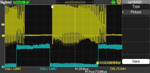
- OV7670live14.6fps.jpg (51.15 KiB) Viewed 354 times
[stevestrong – Wed Aug 02, 2017 12:31 pm] –
After thinking a bit more on this, I think now that byte swapping could be done easily without additional software processing.
Background:
– the order in which RGB565 pixel data is stored in memory is: RG1, GB1, RG2, GB2, …
– in 8 bit mode the SPI data is sent in the same linear order in which it was written: RG1, GB1, RG2, GB2, …
– in 16 bit mode the high byte of an uint16_t value will be sent first over SPI and because of the little endianess the first byte to be sent will be the second written byte, followed by the first written byte: GB1, RG1, GB2, RG2, …So byte swapping reduces to changing SPI data size between 8 bit and 16 bit before using SPI.dmaSend().
Don’t forget, the actual default SPI mode for ILI9341 lib is 16 bit.
SPI.setDataSize(DATA_SIZE_8BIT); // set to 8 bit mode

SPI.dmaSend(...); // tft.pushColors(...);

SPI.setDataSize(DATA_SIZE_16BIT); // set back to 16 bit mode
[stevestrong – Wed Aug 02, 2017 5:55 pm] –
It looks that I have found the good working limit, it is at 11 fps, a prescaler value of 3.The next level would be a prescaler value of 2, which would generate 14.5 fps, but this is exactly the limit where the SPI transfer fills up completely the horizontal blanking interval. In this case sporadically the SPI transfer overlaps the pixel acquisition DMA transfer, which manifests in sporadic wrong pixels on the display.
I have tried to use SPI.dmaSendAsync(), but this does not help at all. When the two DMA transfers are overlapping, they massively influence (delay) each other, so that the pixel data is corrupt => unusable.
[blue = HREF, yellow = SPI CLK] OV7670live14.6fps.jpgIs it maybe possible to play around with the PLL and the prescaler of the camera to get different pixel clock, so that we could maybe get a higher fps (up to 14)?
Btw, I tried overclocking CPU @ 128MHZ, it does not look well, I think the camera does not support that high pixel clock (PLL out of range?), the colors are not right, the update frequency is lower, despite the prescaler value of 2 of higher.
The best working performance for QVGA is achieved with overclocked CPU@80MHZ -> 12.5fps = OK.
I attach the code as lib, extract to /Arduino/libraries, including the sketch as example.
For this to work, the latest master version of my repo is needed.
Thanks.
I think we need to make it work at 72MHz to retain USB if possible, even if this has a lower frame rate
I downloaded you repo and used it instead of my repo, and I copied you zip to make a library, but it did not work for me
I get a blank screen
PS. I saw your fix to dma.h for the typo, so I’ve committed your fix for this into my repo.
Thanks
Roger
[stevestrong – Thu Aug 03, 2017 6:16 am] –
Roger, did you check the connection scheme between bp and camera? It is in the example ino file.
No.
I just took you zip file and used it as a library
I also needed to initially add Streaming.h to the sketch folder, but I suspect you may have that in your repo
Anyway, I downloaded your repo, replaced mine, and tried it, but got a blank screen.
Then I ran out of time this morning as I had to start work.
As its now the end of the working day for me, I’ll try again this evening.
BTW. One useful addition I had in my code is to flash the LED each frame.
I may add that code, as it helps to know if the code is detecting the VSYNC
[RogerClark – Thu Aug 03, 2017 6:59 am] –
One useful addition I had in my code is to flash the LED each frame.
I have it in the code, too, but somehow didn’t work for me, and wasted no time to find out why.
digitalWrite(LED_PIN, !digitalRead(LED_PIN)); // does not work for me
You use different pins for the data from the camera to the original example !
Also I was using different pins for the ILI9341
However I tried my old sketch and it doesnt work, so I think perhaps one of the wires has come loose.
Actually, I’ll need to swap back to my version of the repo in case its something to do with your repo
I’ll do some tests later after our evening meal
[RogerClark – Thu Aug 03, 2017 7:54 am] –
Also I was using different pins for the ILI9341
Yes, indeed, sorry for the confusion, I just took my previously used pins for the LCD and added those from the camera, which should be the same as in the example from github (https://github.com/indrekluuk/LiveOV7670_stm32-arduino), with the needed change of connecting PCLK to PA1 (TI2) instead of PB4.
Btw, I would recommend you this PR, too: https://github.com/stevstrong/Arduino_STM32/pull/2. It is vital for a good working timer capture input example.
Something else is different in your repo.
Perhaps the ILI9341 lib
I switched back to my repo master, and my old example code works fine (I need to select -O2 in the new menu but thats all)
But when I use your repo, the screen stays green
I get a flashing LED to indicate the camera is getting VSYNC, but it looks like its not sending it to the display, as the display stays green, which I use to indicate the camera setup is has succeeded
I’ll need to selectively change things, as your SPI lib and also the ILI9341 is different
But on the first sight I cannot imagine that SPI would cause your code not to work. I just cleaned it up and added a new function.
OTOH, ILI9341 lib may be critical, which in turn seems to work for you (green screen).
I’m not sure why.
I’ve attached my old code.
It does pixel and line doubling, to convert from QQVGA from the camera to the QVGA (ILI9341 display)
The code is a bit of a hack, but its not that much different from the original.
Note. My display pinout is different from yours, as are the camera signals (apart from I2C)
I don’t know why it worked for you …
This issue was exactly the reason why I implemented the pushColors() function, because inside of this function those necessary control bits are set as needed.
Btw, we could maybe achieve 20..40fps LCD update rate with QQVGA camera resolution by doubling pixels and lines, and using DMA-based pixel reading, with input double buffering.
Would it be of interest to try out how far we can go by up-scaling this lower resolution?
#define TFT_CS PA2
#define TFT_DC PA0
#define TFT_RST PA1
And didnt deliberately pull CS to GND all the time.
I did a git diff but it found loads of small differences between the 2 different versions of the library, so its difficult to know which change stopped it working
The original graphics test works OK, and your screen clear and initial text work OK.
So its looks like its just your function to send the image which may not work for me
[stevestrong – Tue Aug 01, 2017 2:20 pm] –
You don’t need to toggle CS and DC between consecutive data reads (SPI.transfers…)
Even without toggling CS and DC between reads I’m still getting 255 255 255. Also setting SPI.setDataSize(DATA_SIZE_8BIT); before data reads doesn’t help ![]()
BTW. The reason the LED does not flash for you, is because the pinmode to set it to OUTPUT is in blink() and not setup
I copied the pinmode to setup and moved the #define to the top of the file and the LED works now.
I’m no sure why you moved
// PB4 – pixel clock
to
// PA1 – pixel clock PCLK
i.e my camera pin mapping is
// A8 - camera clock

// PB3 - href

// PB4 - pixel clock

// PB5 - vsync

// PB6 - i2c Clock

// PB7 - i2c data

// PB8..PB15 pixel byte
This also means that
#define OV7670_PIXEL_CLOCK ((*idr) & BIT4) //((*GPIOB_BASE).IDR & BIT4)[konczakp – Thu Aug 03, 2017 10:15 am] –
Even without toggling CS and DC between reads I’m still getting 255 255 255. Also setting SPI.setDataSize(DATA_SIZE_8BIT); before data reads doesn’t help
I will test this in the evening.
Just for the record: Supporting info: ILI9341.PDF
– chap.7.6.2. 4-line Serial Interface, page 64
– chap.8.2.24. Memory Read (2Eh), page 116
You are my savior – I’ve tried everything.
Now I’m struggling with the reading, I get always 0.
http://www.avrfreaks.net/comment/223451 … nt-2234511
Trying to sync the ILI9341_STM lib with that from Adafruit.
I have not investigated this yet
I will unsolder my pixel clock and connect it to the same pin you are using
BTW.
I worked out why my code works even though CS is not permanently pulled low
Its because fillRect leaves CS LOW, as it doesn’t pull it high after the dmaSend is complete
This is potentially a bug in the ILI9341 library, if anyone wanted to use the display on the same SPI channel / pins as another device
I’m not sure if my code would work if CS was driven high by the library and then driven low by my code, as its possible that a new AddressWindow would need to be sent to the display, rather than piggy-backing on the previous, fillRect(), command
I think it is the fillScreen() function which misses the CS set back to high (see this line), the fillRect() has it (here).
In my repo I have corrected this with the latest commit (see here), it is within the PR I sent you.
Otoh, setAddrWindow() also misses it, this is why it worked for you.
Btw, I plan to do one more optimization on this lib, to remove some of the DC pin toggling: it will be done only within the writecommand() function, the rest of the time it can stay high (data access).
Its only the FillRect which made it work for me.
Thanks. Your code is working well for me now.
Amazing work…..
I re-wrired my board. I had been using PA1 for the TFT (reset) so I moved this to PA3 and moved Pixel Clock to PA1
I initially used your copy of the repo but I’ve now added pushColors() to the existing version of the ILI9341 library, so that anyone using the latest copy my repo can now use your code
Thanks again…
PS. I guess the next thing we need to get working is reading from the display, but it sounds more difficult than we imagined.
Reading of registers and GRAM data now really works.
The clue is that for reading the SPI clock may not be higher than 24MHz (info taken from original Adafruit lib).
And that CS pin MUST be kept low during the entire reading process, it may not toggle.
I also did a further speed improvement and other stuff on the ILI9341 lib.
Output from graphics test (combined with read test):
ILI9341 Test!

Display Power Mode: 0x9C

MADCTL Mode: 0x48

Pixel Format: 0x5

Image Format: 0x9C

Self Diagnostic: 0xC0
Read single pixel test
------------------------------
Write pixel: 0x1234
Read pixel: 0x1234
Read multiple pixel test
------------------------------
Write pixels: 0x1234, 0x5678, 0x9012, 0x3456
Read 4 pixels: 0x1234, 0x5678, 0x9012, 0x3456
Benchmark Time (microseconds)
Screen fill 170777
Text 30574
Lines 151856
Horiz/Vert Lines 15086
Rectangles (outline) 10120
Rectangles (filled) 354913
Circles (filled) 93002
Circles (outline) 119291
Triangles (outline) 34098
Triangles (filled) 139567
Rounded rects (outline) 43011
Rounded rects (filled) 400061
Done!
I’ll pull your repo to my local machine
Its not working for me
Did you update your library as well ?
When I pulled I got a replacement ILI9341 library and a updated graphics test (and the FreeRTOS changes)
But when I run the camera sketch that was working OK, just get a flickering display
Does the latest ILI9341 lib work with the camera ?
BTW. The graphics test needs Streaming, but I even when I locally pull your repo, it doesnt find Streaming.h, so I have to manually put it in the sketch folder.
Edit
Graphics test does not work for me either.
I suspect its something to do with the changes you made to CS
No worries
I’ll see if I can figure out why it doesn’t work for me.
I’ve tried to add your code to read pixels into the current library without all your other changes, but at the moment its not reading any data.
Its possible I’ve done something wrong when copying the code and modify it, but its getting too late now for me to figure out whats going wrong, as I think I’m going to need to hook up the logic analyser to the board, to confirm whats being sent to it
I will try to look again tomorrow, but in the mean time, perhaps you better zip up your ILI9341 lib and post it here or perhaps also to General, and see if a few more people can test it.
I figured out why your camera example did not work with the new ILI9341 library
Its because on line 135 you have a debug pin defined as PA0, and am using that pin for the display DC pin
I suspect the changes to the library where you now return CS to high after transfers, made a difference to how the state of DC was latched on changing
Anyway. Now that I changed the debug pin to PB0
//-----------------------------------------------------------------------------

#define DBG_PIN PB0

#define SET_DBG digitalWrite(DBG_PIN, HIGH)

#define CLR_DBG digitalWrite(DBG_PIN, LOW)

//-----------------------------------------------------------------------------
Sorry about the debug pin, I will remove i, I used it only for a short time.
Anyway, I did some more experiments, I can now go with the frame rate from 11fps up to 12fps by using a different clock source.
Originally, the XCLK is taken from the MCO (CPU clock output) and is 36MHz. This is then connected in the camera to a PLL multiplier (currently bypassed) and then to the pixel generator via a prescaler.
For the actually 11fps the prescaler has a value of 3 (actually means dividing the clock from PLL by 3+1) leaeding to a pixel clock of 9MHz..
But an equivalent pixel frequency can be also generated with a PWM output of 36MHz divided my 4 (=9MHz), and an active camera PLL to multiply by 4. The prescaler then gets the same 36MHz as before and dividing it again by 4 we get same fps as previously.
With a simple trick, if I set PWM output 36MHz divided by 3 (instead of 4 before) will result in an XCLK of 12MHz, multiplied by the PLL x4 = 48MHz.
Then, using a lower camera prescaler of 4 (divide by 5), results in pixel clock of 9.6MHz, ~12fps.
This is ~8% increase in fps, without overclocking the CPU, and having a working serial USB.
The image looks marginally better.
One could go now further and overclock the CPU and try different combinations of PWM divider and prescaler dividers to get maybe even more fps.
EDIT
Funny thing, I now have a working 15fps, with a good picture. I don’t know why it works, but it does.
https://github.com/stevstrong/LiveOV7670_STM32
(code cleaned up, changed MCO to PWM)
I was about to test Your lib with new sketch for Camera but there is missing “Streaming.h”. What is it and where to find it?
.
Or here: viewtopic.php?f=9&t=2425
/arduino-1.6.9/hardware/Arduino_STM32_Camera/STM32F1/libraries/LiveOV7670_STM32/examples/LiveOV7670stm32/LiveOV7670stm32.ino: In function 'void DMA_Setup()':

/arduino-1.6.9/hardware/Arduino_STM32_Camera/STM32F1/libraries/LiveOV7670_STM32/examples/LiveOV7670stm32/LiveOV7670stm32.ino:115:5: warning: 'void dma_setup_transfer(dma_dev*, dma_channel, volatile void*, dma_xfer_size, volatile void*, dma_xfer_size, uint32)' is deprecated (declared at /arduino-1.6.9/hardware/Arduino_STM32_Camera/STM32F1/system/libmaple/stm32f1/include/series/dma.h:563) [-Wdeprecated-declarations]
dma_setup_transfer(DMA1, DMA_CH2,

^

/arduino-1.6.9/hardware/Arduino_STM32_Camera/STM32F1/libraries/LiveOV7670_STM32/examples/LiveOV7670stm32/LiveOV7670stm32.ino:118:18: warning: 'void dma_setup_transfer(dma_dev*, dma_channel, volatile void*, dma_xfer_size, volatile void*, dma_xfer_size, uint32)' is deprecated (declared at /arduino-1.6.9/hardware/Arduino_STM32_Camera/STM32F1/system/libmaple/stm32f1/include/series/dma.h:563) [-Wdeprecated-declarations]
(DMA_MINC_MODE));//| DMA_CIRC_MODE));

^

/arduino-1.6.9/hardware/Arduino_STM32_Camera/STM32F1/libraries/LiveOV7670_STM32/examples/LiveOV7670stm32/LiveOV7670stm32.ino: In function 'void loop()':

LiveOV7670stm32:223: error: 'DMA_ISR_TCIF' was not declared in this scope

while ( !(dma_get_isr_bits(DMA1, DMA_CH2) & DMA_ISR_TCIF) ) {

^

LiveOV7670stm32:233: error: 'DMA_ISR_TCIF' was not declared in this scope

if ( dma_get_isr_bits(DMA1, DMA_CH2) & DMA_ISR_TCIF ) {

^

exit status 1

'DMA_ISR_TCIF' was not declared in this scope
I don’t know if I am doing the calculation incorrectly, but..
If the SPI to the display is running at DIV2, it’s 36MHz.
So theoretical maximum pixels per second is 36,000,000 / 16, as they are 16 bit pixels.
That equals 2,250,000
The display is 320 x 240 pixels. So that is 76,800 pixels.
So the number of times per second that the SPI could send all the pixels, would be 2,250,000 / 76,800
Which is just over 29
Of course this would require data to be sent to the display at the same time as it is being received from the camera, and it would not be possible to get 29fps as there would be breaks in the transfer to the display.
But using double buffering, higher frame rates than you are currently achieving may be possible.
It would only require 1 line to be double buffered ( circular buffereing would also be ok, as long as it’s at least 2 lines long)
[RogerClark – Sun Aug 06, 2017 9:58 pm] –
But using double buffering, higher frame rates than you are currently achieving may be possible.
Yes, theoretically. But not in practice.
My experiments showed that with this pixel sampling method (DMA) is not possible to get higher frame rates.
The SPI DMA will influence strongly the DMA-based pixel scanning (which is very time critical) so that pixels get lost. I think this is an architectural limitation of the hardware. This results in a corrupted image.
I attached in one of my previous posts a picture where HREF and DMA were overlapping. That small overlapping area caused already distorted colors on the whole picture.
Even with 15fps, I have to correct (clear to 0) the first two pixels which will occasionally be corrupted.
The funny thing is that I tried 13fps, too, but it did not work (corrupted colored image).
So I suspect that at 15fps the DMA is reading actually with one pixel delay – the internal timer takes probably a lot of clock cycles to trigger the DMA.
I thought that as @racemaniac’s test managed multiple simultaneous DMA transfers without noticeable loss in performance, then higher frame rates may be possible.
But I understand that the timing on the camera pixel sampling is critical, and the SPI transfers must be delaying this sufficiently that cause the image to get corrupted.
BTW.
Did you try changing the priority of the SPI DMA ?
I see that in void SPIClass::dmaTransferSet(void *transmitBuf, void *receiveBuf) {
it has
dma_set_priority(_currentSetting->spiDmaDev, _currentSetting->spiRxDmaChannel, DMA_PRIORITY_VERY_HIGH);
And I’m not sure if this setting is still active when the dmaSend is being used, becase
dmaSendSet only has
dma_set_priority(_currentSetting->spiDmaDev, _currentSetting->spiTxDmaChannel, DMA_PRIORITY_LOW);
and does not modify the receive priority
But I think perhaps it doesnt matter as we are only sending and not receiving ??
It does not use DMA to transfer the data
There are some threads where people have tested the maximum throughput of the Serial USB, but its not going to be fast enough to transfer over 2Mb per second to the PC (needed for 320×240 @ 2 bytes per pixel @ 15 frames per second)
I’d recommend you play with Steve’s latest version and keep the DMA from the camera but at a much lower the frame rate, and try passing one line at a time to the USB Serial, a line at a time.
(actually I’m not sure the USB buffer is enough for a whole line. You’d need to check the core code and potentially increase the usb buffer accodingly)
[RogerClark – Mon Aug 07, 2017 1:09 am] –
But I think perhaps it doesnt matter as we are only sending and not receiving ??
Correct. Receiving SPI must have higher prio than SPI send, but we are not receiving in this project anything over SPI, so this is not blocking us.
The maximum throughput over USB serial I measured ~600kBps, you would need ~2.3MBps, which is not possible.
Maybe 4fps would be doable.
I don’t know whether there are some serial-USB adapters which support such a high throughput, you could then eventually send the data over USART.
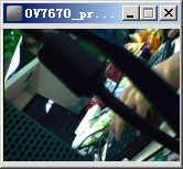
- 1.jpg (15.14 KiB) Viewed 312 times
He sends data out while he reads pixels at 1MBaud.
[Pito – Tue Aug 08, 2017 6:53 am] –
He sends data out while he reads pixels at 1MBaud.
can stm32 usb serial do the same thing, with interrupt off, using the register way?
USB operation requires interrupts to be enabled.
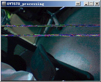
- 4.jpg (37.17 KiB) Viewed 512 times
Couldn’t you simply attach the images “normally”?
I have downloaded Your repo, ArduinoStreaming which You pointed me and also LiveOV7670 from Your repo. I have exactly the same connections for the camera as You and a slightly different connections for the screen.
// TFT connection:

// PB4 - TFT reset

// PA0 - TFT D/C (data/command)

// PA2 - TFT chip select

// PA5 - TFT SPI CLK

// PA6 - TFT SPI MISO

// PA7 - TFT SPI MOSI
// Camera connection:
// PA8 - camera clock
// PB3 - HREF
// PA1 - pixel clock PCLK
// PB5 - VSYNC
// PB6 - I2C Clock
// PB7 - I2C data
// PB8..PB15 - pixel data
.
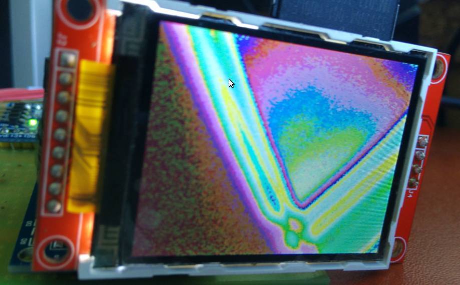
- Selection_001.jpg (57.43 KiB) Viewed 473 times
[konczakp – Wed Aug 09, 2017 11:38 am] –
Your repo is missing
#define TIMER_CCMR_CCS_OUTPUT           0x0

#define TIMER_CCMR_CCS_INPUT_TI1        0x1

#define TIMER_CCMR_CCS_INPUT_TI2        0x2

#define TIMER_CCMR_CCS_INPUT_TRC        0x3
I think I will merge your latest SPI with the master, and also update the ILI9341 lib with your version, so that anyone can use the OV7670 code.
I went a step back and again I have tried Indrekluuk’s code for changed pins. Everything worked fine. So the next step I’ve tried to rewrite readPixel function from Stevestrong’s repo of ILI9341 lib.
in Adafruit_ILI9341_STM.cpp I have:
void Adafruit_ILI9341_STM::writecommand(uint8_t c) {

*dcport &=  ~dcpinmask;

*csport &= ~cspinmask;
spiwrite(c);
*csport |= cspinmask;
}
uint16_t Adafruit_ILI9341_STM::readPixel(int16_t x, int16_t y)
{
SPI.beginTransaction(SPISettings(24000000ul, MSBFIRST, SPI_MODE0, DATA_SIZE_8BIT));
writecommand(ILI9341_CASET); // Column addr set
spiwrite16(x);
spiwrite16(x);
writecommand(ILI9341_PASET); // Row addr set
spiwrite16(y);
spiwrite16(y);
writecommand(ILI9341_RAMRD); // read GRAM
SPI.transfer(0x00); //dummy read
uint8_t r = SPI.transfer(0x00);
uint8_t g = SPI.transfer(0x00);
uint8_t b = SPI.transfer(0x00);
cs_set();
SPI.beginTransaction(SPISettings(48000000ul, MSBFIRST, SPI_MODE0, DATA_SIZE_16BIT));
return color565(r, g, b);
}
Toolchain standalone version (gcc-arm-none-eabi-6-2017-q2-update) I got it from here: https://developer.arm.com/open-source/g … /downloads
Streaming lib from here: https://www.arduino.cc/en/reference/libraries
STM32 hardware for IDE from Stevestrong’s repo: https://github.com/stevstrong/Arduino_STM32
LiveOV7670 from Stevestrong’s repo: https://github.com/stevstrong/LiveOV7670_STM32
with a small change in code for pinout changes :
instead:  Adafruit_ILI9341_STM tft(PA4, PA3, PA2); // SS, DC, RST

I got     Adafruit_ILI9341_STM tft(PA2, PA0, PB4); // SS, DC, RST
My new version with reworked CS and DC pin toggling will do it right.
When I get back home (in couple of days) I will test and generate for you a binary if you indicate your connections.
Just use the compiler that is installed with the IDE
Note. I think that the STM core may require a newer version of the compiler, but if you need to use both LibMaple and STM’s core, you will need to manage how you handle having 2 different versions of the compiler so that each core uses the correct version
Adafruit_ILI9341_STM tft(PA2, PA0, PB4); // SS, DC, RST
Now it works correctly. I have commited the bugfix on github.
Attached the BIN file according to your pinning:
Adafruit_ILI9341_STM tft(PA2, PA0, PB4); // SS, DC, RST
Camera connection:

PA8 - XCLK

PB3 - HREF

PA1 - PCLK

PB5 - VSYNC

PB6 - SIDC via 10k

PB7 - SIDO via 10k

PB8..PB15 -  D0..D7

3.3v - Reset

PWDN - GND
// TFT connection:

// PB4 - TFT reset

// PA0 - TFT D/C (data/command)

// PA2 - TFT chip select

// PA5 - TFT SPI CLK

// PA6 - TFT SPI MISO

// PA7 - TFT SPI MOSI
// Camera connection:

// PA8 - camera clock

// PB3 - HREF

// PA1 - pixel clock PCLK

// PB5 - VSYNC

// PB6 - I2C Clock (2k7)

// PB7 - I2C data (2k7)

// PB8..PB15 - pixel data
Works fine for me.
I pulled the latest version of the library, and the only thing I changed are the TFT pins, as I soldered them on slightly different pins
Adafruit_ILI9341_STM tft = Adafruit_ILI9341_STM(PA2, PA0, PA3);
[stevestrong – Sun Sep 03, 2017 7:52 am] –
It is releasing to know that some else also managed to get it work.
No worries
I think that @konczakp has either wired the camera incorrectly or has some sort of hardware fault.
BTW. I presume konczakp has pullup resistors on the I2C connections to the camera.
Do you get the complete message on the LCD?
4k7 5v0
seem to be most common in use i’ve seen
have you rounded corners / edges on the signals, rc effect??
srp
google ‘effect of load resistors on i2c’
I would try at least 4k7, anyway 10k is too much.
I initially had a problem with a dry joint on one pin.
Currently you are using PA1 for the pixel clock, but I cant see how to change it.
What other pins could be used ( with appropriate changes to the Timer and DMA code ) ?
I just turned on my main PC which has the BluePill and camera etc connected to it, and initially I get the same sort of image colour problem that @konczakp was getting
So I power cycled and I then got a better coloured picture but a very low frame rate.
I wonder if this issue is something to do with the I2C setup.
I checked and I’m using 4.7k pullups, which is probably too high.
I don’t recall these problem with the older version of Steve’s library, and I think I may have a backup copy of that, so I will see if I can go back to what I was using previously
Alternatively, the problem could be something to do with the Wire lib, as we are now using Hardware I2C by default – but it has been working with Hardware I2C for me
The previous version of Steve’s library seems more stable
I went back to using the old version and it worked straight away.
@Steve
What did you change ??? (I guess I can look in github or run a multi file diff on the code )
Quite a lot of changes between the 2 versions I have.
There are changes to the registers setup as well as various things, so its really hard to know which change is causing the camera now not generate good video most of the time.
If I force a complete rebuild and upload, sometimes the image video is totally over saturated or the wrong colour, and sometimes its OK
But as its random whether it works or not, its hard to know whether a particular change has fixed it or not
I see that Steve changed the initialisation code so that he sets the hardware control register directly with 0x44444444 which sets the camera data bits to input.
But the older code also sets pinmode for PB3, PB4 and PB5
On my board PB3, PB5,PB7 and PB7 are all being used, so perhaps one of these is not being initialised ??
Definitely something not being initialised
PS. Does anyone know why if I touch the camera data pins (I’m not sure if its the data bits or the VSYNC of HSYNC etc), that the camera goes nuts and I end up with half a picture ?
I find it hard to believe that static from my fingers is doing is, but perhaps its the capacitance of my fingers ?
It was because I had not pulled RESET high
I’ve now pulled RESET to 3.3 via 1k and PWDN LOW via 1k. This stops the problems caused when touch the RESET pin
Unfortunately the problem with the camera intermittently not working is not fixed by this.
I’ve also looked at all the versions that Steve commited to github, and they all have the same problem
The only version that is stable is the version he posted here as a zip.
I’m still trying to track down what the problem is, but the old code that has the setup line
BufferedCameraOV7670_QVGA camera(CameraOV7670::PIXEL_RGB565, BufferedCameraOV7670_QVGA::FPS_11p_Hz);
The frame rates are different for the latest and attached version.
The attached version has 11fps, the latest has 15fps, and this is critical, it is the absolute limit.
You may try lower fps using higher prescaler value, for example 6 instead of 5.
OTOH the I2C signal is clean and the edges are ok (I use 2k7 resistors), so I assume the camera init is always done correctly.
I’m using 4.7k pullups, which work OK with your old version, so I don’t think thats the problem unless you changed something in the Wire code ??
I presume the old version I have must be from the zip file you posted, because it pre-dates the code thats in your github repo
Re: Changing the pre-scaler value to 6
BufferedCameraOV7670_QVGA camera(CameraOV7670::PIXEL_RGB565, (BufferedCameraOV7670_QVGA::Prescaler)6);
I tried again this morning and even with a different pre-scaler it does not work when the board is cold (10 deg)
Can you try putting you board (including the camera) in the fridge and try again
(PS. You probably need to put it all in a plastic bag, and just have the cable come out from the bag, otherwise when you take it out of the fridge it will get a lot of condensation on the board)
PS. I will try changing the I2C pullups to a lower value and see if that fixes it, but as the old code works when the board is cold, I don’t see how that could be the problem.
Edit
I replaced the I2C pullup resistors with 2.7k, but it didnt make any difference
I put my whole test setup (BP+camera+display) in a plastic bag and put in the fridge, and when I took them out again, I get the problem where the LED does not flash at all to indicate that its getting frame pulses
As it warms up, I get video but the colours are all wrong
The old code (from the zip file) always works, even when the board is cold.
I also have the problem of wrong colors in ~1 out of 5 starts.
I have to have a look on it. Only time is missing currently…
No worries
I’m happy using the old version.
I may slowly try to integrate some of the changes from your latest version, but I don’t have much time for that either ![]()
I’m currently trying to design a PCB that will have the BluePill the ILI9341 2.4″ display and the OV7670 camera
- BluePillDisplay.pdf
- (43.73 KiB) Downloaded 22 times
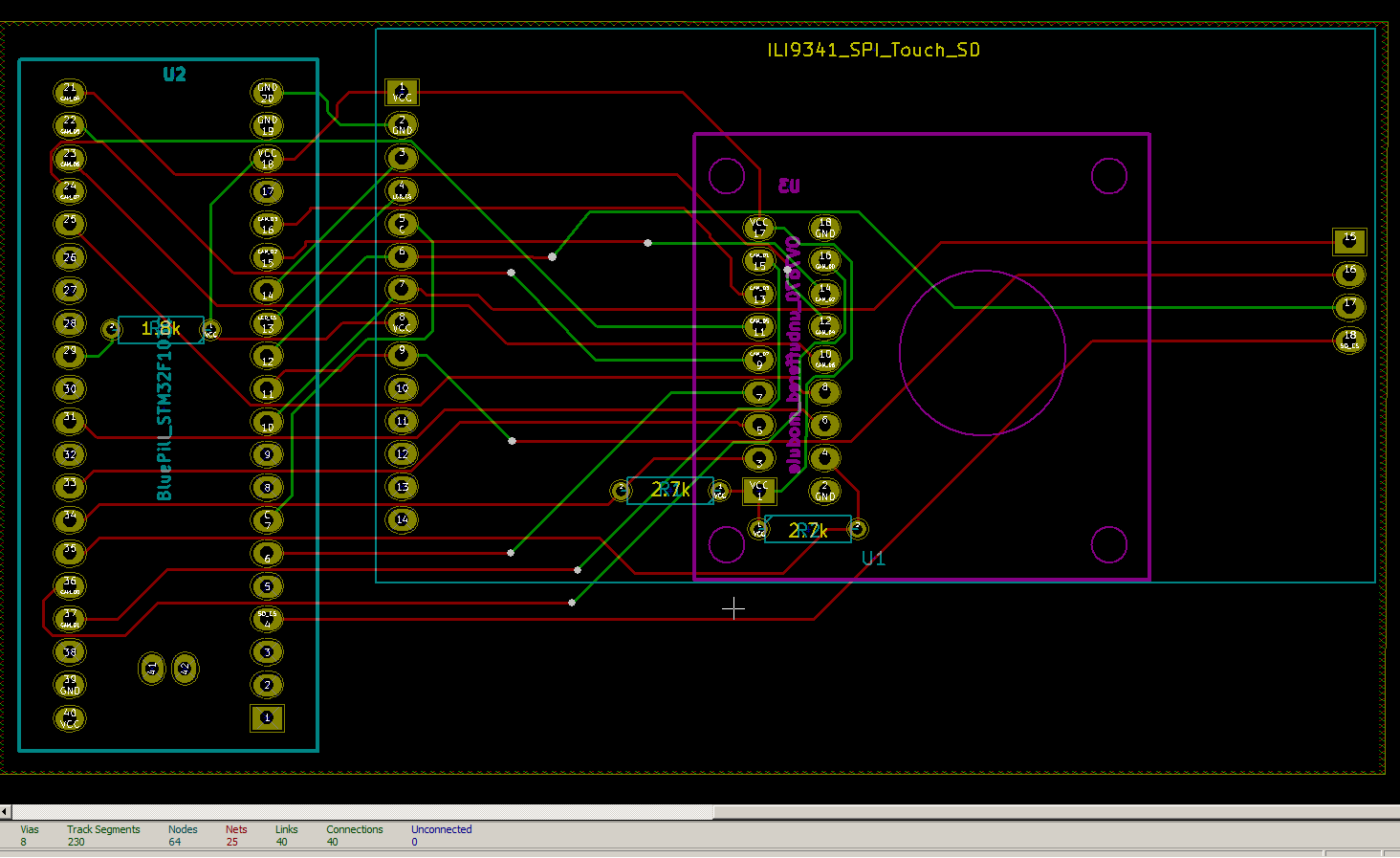
- bp_camera_pcb.png (55.66 KiB) Viewed 322 times
I’m not sure if technically this should be working or not, because I’m sharing the SPI bus with both the SD card and the LCD display, but as they both have their own Chip Select lines, it seems to work.

- LCD_to_SD_test1.png (2.61 KiB) Viewed 267 times
  unsigned long m=millis();

for(int i=0;i<1000;i++)

{

tft.readPixels(0,0,320,0, lineBufLCD);

}

Serial.println(millis()-m);
and a nice JPEG encoder (for STM32L1): https://github.com/mitchd/vt-fox-1/tree … de/encoder
I am already using snippetsnof the BMP code from the Arduno forum, and it seems to work OK.
Thanks for the link to the L1 joeg compressor, but for the F1 I am not sure if it has enough RAM.
Writing to SD is currently very slow if I only write 1 line at a time. ( over 5 seconds)
I should be able to write 12 lines at a time, or potentially even 15 lines, but I have not made that work yet.
My initial calculations were that I could write the 320×240 display to SD in approx, 400mS , but I had not factored the rather slow transfer speed to the SD, whuch is only a few hundred kIlo bytes per second.
So I think the time to write to SD is likely to be around 900mS or perhaps 800mS at best.
I’m still reading the display, line by line, so I can probably shave a few mS off this, but although reading from the LCD can be faster, because the image seems to be upside down, I may still need to flip it vertically in code (in blocks of 12 lines at a time)
BTW.
This harks back to my first job, when I worked on high resolution image processing for the print industry, in the days before a 50mB image could easily be processed by a $10 RPi Zero ![]()
Edit
I did some timing tests, and reading multiple lines from the LCD doesnt look like it will save much time, and is probably not worth the bother at the moment
Time to read 240 lines individually from the LCD would be 116.64 mS
Time to read 240 lines in blocks of 10 from the LCD would be 104.13 mS
However, if I read 10 lines from the display the line(s) buffer would need to be processed to swap the line order, and this is going to add a small amount of time to the total.
It would probably be marginally quicker to do this but it would be less than 10mS on a total time of around 700mS, so at the moment, I don’t think its worth the time to get it working !
PS. I also tried change the Window params to that the window Y direction of the window was -1 e.g. lines 239 to 230 rather than 230 to 239
However, this seemed to result in corrupt image data
(Note I’d need to retest this as I’m also having SPI issues when I attempt to transfer more than 11 lines at a time, so I can’t rule out that being the problem rather than an inverted image window problem)
I’m going to go back to reading the LCD line by line, as I don’t think its going to save any significant time by reading multiple lines because of the time to swap lines, i.e there would need be 3 memcpy calls per pair of lines that are swapped and it would need an additional line of buffering which could not be used for the SD card transfer
I ask because I have had good luck running the sdfat in parallel with other things with a modified driver that uses the new DMA callback functions, and FreeRTOS.
Obviously if the buffers are small, there is no much gain, since the RTOS has to switch tasks and that wastes some cpu cycles, but if the buffers are large enough, say some KB, you may be able to do more things in parallel, perhaps read lines from the camera and write to the card only taking the time of the longest one of them, while the other is ran in the background using cpu time that would be wasted.
It’s pretty similar to what you were doing with the async function with the leds, but since there are callbacks, there is no need to check if the DMAs are over, the spi driver will just call the corresponding ISR when they are.
It my case is just a proof of concept with the WAV player, and goes like this:
Task 1 reads from the SDcard, and sets the data as buffer for another another DMA channel to output to timers.
Task 2 writes some stats to the screen (cpu usage mostly).
Task 3 just draws a cube just to do something with the cpu time.
Some interrupt routines switching buffers.
So when task 1 was before “blocking” in sdfat reading, it doesn’t block anymore and instead does a task switch to task 2 or 3, whichever is ready to execute.
When the spi DMA completes calls a new ISR that tells the RTOS the sdfat task, task1, is ready to execute, and the rtos does a switch back to that task.
Since that’s managed within the sdfat spi driver code, it’s compatible with anything, the other tasks do not need to have any change, they just get executed more frequently.
I forgot how much cpu time I could see saved that way, but it was a few % points, and my code is just reading from the car, writes take even longer so may benefit more.
You could use the same methods for both writing to the card, and reading from the camera, so while both transfers are going in parallel, whatever code needs to run in the cpu can be running.
Both the camera and the SD are on the same SPI bus (SPI1)
I can’t use SPI2 because the camera has to be on specific pins i.e PB8 – PB15 as Steve’s code does a DMA read from the upper half of port B.
(and thats where SPI 2 is located)
I’ll need to check if SPI2 can be remapped, but I’ve got very few pins unused, so it may not be possible to remap as there are some other pins in the circuit which cant be changed because the timers that they are associate with.
I’m not to concerned if it takes 750mS to save to SD, its just strange that I get a sudden slowdown if I use a 12 line buffer, when a 11 buffer is OK.
I’ve tried to save the LCD display after a frame has been read from the camera, but it fails because it looks like the timer or DMA etc is interfering with the SD SPI access somehow.
Here is my code that I’m using to read the display and write to SD
#include <SdFat.h>

#include "Adafruit_ILI9341_STM.h"
#define TFT_CS PB0
#define TFT_DC PA2
#define TFT_RST PB1
Adafruit_ILI9341_STM tft = Adafruit_ILI9341_STM(TFT_CS, TFT_DC, TFT_RST); // Use hardware SPI
const uint8_t SD_CS = PC15;
SdFat sd;
unsigned long testText()
{
tft.fillScreen(ILI9341_BLACK);
tft.setCursor(0, 0);
tft.setTextColor(ILI9341_RED); tft.setTextSize(3);
tft.println("LCD Screen reader\n");
tft.setTextColor(ILI9341_GREEN); tft.setTextSize(3);
tft.println("rogerclark.net\n");
tft.setTextColor(ILI9341_BLUE); tft.setTextSize(3);
tft.println(__TIME__);
tft.setTextSize(2);
return 0;
}
void LCD2SD()
{
const int w = 320;
const int h = 240;
SdFile file;
#define NUM_LINES_BUFFERED 12
uint8_t lineBufSD[w*3*NUM_LINES_BUFFERED];
unsigned char bmpFileHeader[14] = {'B', 'M', 0, 0, 0, 0, 0, 0, 0, 0, 54, 0, 0, 0 };
unsigned char bmpInfoHeader[40] = {40, 0, 0, 0, 0, 0, 0, 0, 0, 0, 0, 0, 1, 0, 24, 0 };
unsigned long m;
char name[] = "LCD_00.bmp";
// if name exists, create new filename
for (int i = 0; i < 100; i++)
{
name[4] = i / 10 + '0';
name[5] = i % 10 + '0';
if (file.open(name, O_CREAT | O_EXCL | O_WRITE))
{
break;
}
}
// create image data
int filesize = 54 + 4 * w * h; // w is image width, h is image height
bmpFileHeader[ 2] = (unsigned char)(filesize );
bmpFileHeader[ 3] = (unsigned char)(filesize >> 8);
bmpFileHeader[ 4] = (unsigned char)(filesize >> 16);
bmpFileHeader[ 5] = (unsigned char)(filesize >> 24);
bmpInfoHeader[ 4] = (unsigned char)( w );
bmpInfoHeader[ 5] = (unsigned char)( w >> 8);
bmpInfoHeader[ 6] = (unsigned char)( w >> 16);
bmpInfoHeader[ 7] = (unsigned char)( w >> 24);
bmpInfoHeader[ 8] = (unsigned char)( h );
bmpInfoHeader[ 9] = (unsigned char)( h >> 8);
bmpInfoHeader[10] = (unsigned char)( h >> 16);
bmpInfoHeader[11] = (unsigned char)( h >> 24);
file.write(bmpFileHeader, sizeof(bmpFileHeader)); // write file header
file.write(bmpInfoHeader, sizeof(bmpInfoHeader)); // " info header
m=millis();
uint8_t t;
int lineOffset;
for (int y = 0 ; y < h ; y++)
{
lineOffset = y%NUM_LINES_BUFFERED *3 * w;
tft.readPixels24(0,(h-1)-y,320,(h-1)-y, lineBufSD + lineOffset);
if ((y+1)%NUM_LINES_BUFFERED==0)
{
// swap colour channels from RGB to BGR
for (int x = 0; x < w * 3 * NUM_LINES_BUFFERED; x+=3)
{
t=lineBufSD[x+2];
lineBufSD[x+2]=lineBufSD[x];
lineBufSD[x]=t;
}
file.write(lineBufSD, 3 * w * NUM_LINES_BUFFERED);
}
}
Serial.print("Saved in ");Serial.print(millis()-m);Serial.println(" mS ");
file.close();
}
void setup()
{
Serial.begin(9600);
delay(500);
Serial.println("Starting");
if (!sd.begin(SD_CS, SD_SCK_MHZ(50)))
{
sd.initErrorHalt();
}
tft.begin();
uint16_t screen_w = ILI9341_TFTHEIGHT;
uint16_t screen_h = ILI9341_TFTWIDTH;
tft.setRotation(1);
testText();// Draw something
// tft.setAddrWindow(0, 0, screen_w, screen_h);
// tft.setCursor(0, 0);
LCD2SD();
}
void loop()
{
}
It looks like the Timer setup code in the LiveOV7670 code
void TIMER_Setup(void)

{

gpio_set_mode(GPIOA, 1, GPIO_INPUT_FLOATING);
// Slave mode: Reset mode (see RM0008, chap. 15.3.14, page 394)
// ------------------------
// The counter and its prescaler can be reinitialized in response to an event on a trigger input.
// Moreover, if the URS bit from the TIMx_CR1 register is low, an update event UEV is generated.
// Then all the preloaded registers (TIMx_ARR, TIMx_CCRx) are updated.
//
// In the following example, the upcounter is cleared in response to a rising edge on TI2 input:
// • Configure the channel 2 to detect rising edges on TI2.
// - Configure the input filter duration (in this example, we don’t need any filter, so we keep IC1F=0000).
// - The capture prescaler is not used for triggering, so you don’t need to configure it.
// - The CC2S bits select the input capture source only, CC2S = 01 in the TIMx_CCMR1 register.
// - Write CC2P=0 in TIMx_CCER register to validate the polarity (and detect rising edges only).
// • Configure the timer in reset mode by writing SMS=100 in TIMx_SMCR register.
// - Select TI2 as the input source by writing TS=101 in TIMx_SMCR register.
// • Start the counter by writing CEN=1 in the TIMx_CR1 register.
//
// The counter starts counting on the internal clock, then behaves normally until TI2 rising edge.
// When TI2 rises, the counter is cleared and restarts from 0.
// In the meantime, the trigger flag is set (TIF bit in the TIMx_SR register) and an interrupt request,
// or a DMA request can be sent if enabled (depending on the TIE and TDE bits in TIMx_DIER register).
//
// This event will trigger the DMA to save the content of GPIOB.IDR[1] to memory.
timer_pause(TIMER2); // stop timer
timer_init(TIMER2); // turn timer RCC on
// configure PA2 = timer 2 channel 2 == input TI2
#define TIMER_RELOAD_VALUE 2 // must be adapted according to the results
// as this mode is not supported by the core lib, we have to set up the registers manually.
//(TIMER2->regs).gen->CR1 = TIMER_CR1_CEN;
(TIMER2->regs).gen->CR2 = 0;
(TIMER2->regs).gen->SMCR = (TIMER_SMCR_TS_TI2FP2 | TIMER_SMCR_SMS_RESET);//TIMER_SMCR_SMS_TRIGGER);
(TIMER2->regs).gen->DIER = (TIMER_DIER_UDE); // enable DMA request on TIM2 update
(TIMER2->regs).gen->SR = 0;
(TIMER2->regs).gen->EGR = 0;
(TIMER2->regs).gen->CCMR1 = TIMER_CCMR1_CC2S_INPUT_TI2; // IC2F='0000', IC2PSC='0', CC2S='01'
(TIMER2->regs).gen->CCMR2 = 0;
(TIMER2->regs).gen->CCER = (TIMER_CCER_CC2P); // inverse polarity, active low
(TIMER2->regs).gen->CNT = 0;//TIMER_RELOAD_VALUE; // set it only in down-counting more
(TIMER2->regs).gen->PSC = 0;
(TIMER2->regs).gen->ARR = 0;//TIMER_RELOAD_VALUE;
(TIMER2->regs).gen->CCR1 = 0;
(TIMER2->regs).gen->CCR2 = 0;
(TIMER2->regs).gen->CCR3 = 0;
(TIMER2->regs).gen->CCR4 = 0;
(TIMER2->regs).gen->DCR = 0; // don't need DMA for timer
(TIMER2->regs).gen->DMAR = 0;
// don't forget to set the DMA trigger source to TIM2-UP
//timer_resume(TIMER2); // start timer
}
The problem is
(TIMER2->regs).gen->DIER = (TIMER_DIER_UDE); // enable DMA request on TIM2 update
Seems to be somehow interfering with the SDFat
If I disable the DMA on TIM2 update, I am able to save a image to SD.
(TIMER2->regs).gen->DIER = (0); // disable DMA request on TIM2 update
After writing to SD card, simply resume the timer (XCLK).
EDIT1
Ah, I think the pixel reading will not work if the XCLK is stopped.
In this case one should temporarily de-activate the timer DMA, or the DMA channel itself.
And resume it after SD card writing.
EDIT2
I admit, it is strange that the timer DMA conflicts with the SPI DMA.
I think Victor made a comprehensive study on what happens when both SPI 1 and 2 runs in parallel (with DMA). I think he concluded that they are conflicting when SPI 1 runs with 36MHz, some data bytes are sporadically lost.
I had to disable the DMA
(TIMER2->regs).gen->DIER = (0); // disable DMA request on TIM2 update
Hmm.
Just running the first part of code in Timer_setup()
void TIMER_Setup(void)

{

gpio_set_mode(GPIOA, 1, GPIO_INPUT_FLOATING);

timer_pause(TIMER2); // stop timer

timer_init(TIMER2);  // turn timer RCC on
#define TIMER_RELOAD_VALUE 2 // must be adapted according to the results
// as this mode is not supported by the core lib, we have to set up the registers manually.
//(TIMER2->regs).gen->CR1 = TIMER_CR1_CEN;
(TIMER2->regs).gen->CR2 = 0;
(TIMER2->regs).gen->SMCR = (TIMER_SMCR_TS_TI2FP2 | TIMER_SMCR_SMS_RESET);//TIMER_SMCR_SMS_TRIGGER);
(TIMER2->regs).gen->DIER = (TIMER_DIER_UDE); // enable DMA request on TIM2 update
    timer_pause(TIMER2); // stop timer

dma_disable(DMA1, DMA_CH2);

dma_clear_isr_bits(DMA1, DMA_CH2);
I’ll try that
BTW.
Currently after writing to SD, just re-enabling the Timer DMA enable does not start the camera running again, but if I have to completely re-init the timer and DMA etc that would be OK, as saving to SD is not a a quick process as it takes around 700mS
  //timer_pause(TIMER2); // stop timer

dma_disable(DMA1, DMA_CH2);

dma_clear_isr_bits(DMA1, DMA_CH2);I don’t understand why, but calling
   dma_disable(DMA1, DMA_CH2);

dma_clear_isr_bits(DMA1, DMA_CH2);
Where is the defined readPixels24()? I think it should read and stores 4 bytes instead of 3, because as far as I know the BMP pixel data must be 4 bytes aligned.
uint16_t Adafruit_ILI9341_STM::readPixels24(int16_t x1, int16_t y1, int16_t x2, int16_t y2, uint8_t *buf)

{

mSPI.beginTransaction(SPISettings(_safe_freq, MSBFIRST, SPI_MODE0, DATA_SIZE_8BIT));
writecommand(ILI9341_CASET); // Column addr set

spiwrite16(x1);

spiwrite16(x2);

writecommand(ILI9341_PASET); // Row addr set

spiwrite16(y1);

spiwrite16(y2);

writecommand(ILI9341_RAMRD); // read GRAM

(void)spiread();             //dummy read

uint8_t r, g, b;

uint16_t len = (x2-x1+1)*(y2-y1+1);

uint16_t ret = len;
mSPI.dmaTransfer(buf, buf, len*3);

cs_set();
mSPI.beginTransaction(SPISettings(_freq, MSBFIRST, SPI_MODE0, DATA_SIZE_16BIT));

return ret;

}
I have it wired like this
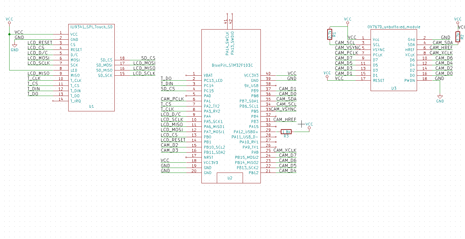
- lcd_sd_camera_blue_pill.png (31.55 KiB) Viewed 712 times
Looks like SD leave SPI in 8 bit mode, but the ILI9341 lib needs 16 bit mode
So I added a call to set into 16 bit before writing the text to the LCD, and it now saves the LCD screen multiple times
#include <SdFat.h>

#include "Adafruit_ILI9341_STM.h"
#define TFT_CS PB0
#define TFT_DC PA2
#define TFT_RST PB1
Adafruit_ILI9341_STM tft = Adafruit_ILI9341_STM(TFT_CS, TFT_DC, TFT_RST); // Use hardware SPI
const uint8_t SD_CS = PC15;
SdFat sd;
unsigned long testText()
{
SPI.setDataSize(DATA_SIZE_16BIT);
tft.fillScreen(ILI9341_BLACK);
tft.setCursor(0, 0);
tft.setTextColor(ILI9341_RED); tft.setTextSize(3);
tft.println("LCD Screen reader\n");
tft.setTextColor(ILI9341_GREEN); tft.setTextSize(3);
tft.println("rogerclark.net\n");
tft.setTextColor(ILI9341_BLUE); tft.setTextSize(3);
tft.println(__TIME__);
tft.println(random(100000));
return 0;
}
void LCD2SD()
{
const int w = 320;
const int h = 240;
SdFile file;
#define NUM_LINES_BUFFERED 12
uint8_t lineBufSD[w * 3 * NUM_LINES_BUFFERED];
boolean doFileActions = true;
unsigned char bmpFileHeader[14] = {'B', 'M', 0, 0, 0, 0, 0, 0, 0, 0, 54, 0, 0, 0 };
unsigned char bmpInfoHeader[40] = {40, 0, 0, 0, 0, 0, 0, 0, 0, 0, 0, 0, 1, 0, 24, 0 };
unsigned long m;
char name[] = "LCD_00.bmp";
if (doFileActions)
{
// if name exists, create new filename
for (int i = 0; i < 100; i++)
{
name[4] = i / 10 + '0';
name[5] = i % 10 + '0';
if (file.open(name, O_CREAT | O_EXCL | O_WRITE))
{
break;
}
}
}
// create image data
int filesize = 54 + 4 * w * h; // w is image width, h is image height
bmpFileHeader[ 2] = (unsigned char)(filesize );
bmpFileHeader[ 3] = (unsigned char)(filesize >> 8);
bmpFileHeader[ 4] = (unsigned char)(filesize >> 16);
bmpFileHeader[ 5] = (unsigned char)(filesize >> 24);
bmpInfoHeader[ 4] = (unsigned char)( w );
bmpInfoHeader[ 5] = (unsigned char)( w >> 8);
bmpInfoHeader[ 6] = (unsigned char)( w >> 16);
bmpInfoHeader[ 7] = (unsigned char)( w >> 24);
bmpInfoHeader[ 8] = (unsigned char)( h );
bmpInfoHeader[ 9] = (unsigned char)( h >> 8);
bmpInfoHeader[10] = (unsigned char)( h >> 16);
bmpInfoHeader[11] = (unsigned char)( h >> 24);
if (doFileActions)
{
file.write(bmpFileHeader, sizeof(bmpFileHeader)); // write file header
file.write(bmpInfoHeader, sizeof(bmpInfoHeader)); // " info header
}
m = millis();
uint8_t t;
int lineOffset;
for (int y = 0 ; y < h ; y++)
{
lineOffset = y % NUM_LINES_BUFFERED * 3 * w;
tft.readPixels24(0, (h - 1) - y, 320, (h - 1) - y, lineBufSD + lineOffset);
if ((y + 1) % NUM_LINES_BUFFERED == 0)
{
// swap colour channels from RGB to BGR
for (int x = 0; x < w * 3 * NUM_LINES_BUFFERED; x += 3)
{
t = lineBufSD[x + 2];
lineBufSD[x + 2] = lineBufSD[x];
lineBufSD[x] = t;
}
if (doFileActions)
{
file.write(lineBufSD, 3 * w * NUM_LINES_BUFFERED);
}
}
}
Serial.print("Saved in "); Serial.print(millis() - m); Serial.println(" mS ");
if (doFileActions)
{
file.close();
}
}
void setup()
{
Serial.begin(9600);
delay(500);
Serial.println("Starting");
if (!sd.begin(SD_CS, SD_SCK_MHZ(50)))
{
sd.initErrorHalt();
}
tft.begin();
uint16_t screen_w = ILI9341_TFTHEIGHT;
uint16_t screen_h = ILI9341_TFTWIDTH;
tft.setRotation(1);
}
void loop()
{
testText();// Draw something
LCD2SD();
delay(1000);
}
To get SD working, I removed the resistors and also shorted the link beside the 3.3V regulator on the LCD board, so that the SD card receives 3.3V instead of 3V
I’m not sure if I needed to do either of these but the SD works for me.
I’ve kinda got it working
//

// Created by indrek on 4.12.2016.

//

// Adapted for ILI9341 by stevestrong on 29.07.2017

//

#include <LiveOV7670_stm32_OK.h>

#include <Adafruit_ILI9341_STM.h>

#include <SdFat.h>
const uint8_t SD_CS = PC15;
SdFat sd;
// TFT connection:
// PB1 - TFT reset
// PA2 - TFT D/C (data/command)
// PB0 - TFT chip select
// PA5 - TFT SPI CLK
// PA6 - TFT SPI MISO
// PA7 - TFT SPI MOSI
// Camera connection:
// PA8 - camera clock
// PB3 - HREF
// PA1 - pixel clock PCLK
// PB5 - VSYNC
// PB6 - I2C Clock
// PB7 - I2C data
// PB8..PB15 - pixel data
// CPU@72MHZ -> 11fps, CPU@80MHZ-> 12.5fps
BufferedCameraOV7670_QVGA camera(CameraOV7670::PIXEL_RGB565, BufferedCameraOV7670_QVGA::FPS_11p_Hz);
#define LED_PIN PC13
#define TFT_CS PB0
#define TFT_DC PA2
#define TFT_RST PB1
Adafruit_ILI9341_STM tft = Adafruit_ILI9341_STM(TFT_CS, TFT_DC, TFT_RST); // Use hardware SPI
#define SD_CS PC15
// Normally it is a portrait screen. Use it as landscape
uint16_t screen_w = ILI9341_TFTHEIGHT;
uint16_t screen_h = ILI9341_TFTWIDTH;
uint16_t screenLineIndex;
uint8_t bufIndex;
#define PIXELS_PER_LINE ILI9341_TFTHEIGHT
// The GPIO.IDR register can be only accessed in word (32 bit) mode.
// Therefore a 4 times larger buffer should be allocated to one line.
// But because for each pixel we need 2 reads, the buffer should be doubled again.
// The useful bytes are packed in the same buffer after reading is finished.
// This is a lot of wasted memory, but it runs with DMA, which is a huge benefit!
#define PIXEL_BUFFER_LENGTH (2*PIXELS_PER_LINE+1)
uint8_t pixBuf[2][PIXEL_BUFFER_LENGTH];
//-----------------------------------------------------------------------------
void TIMER_Setup(void)
{
gpio_set_mode(GPIOA, 1, GPIO_INPUT_FLOATING);
// Slave mode: Reset mode (see RM0008, chap. 15.3.14, page 394)
// ------------------------
// The counter and its prescaler can be reinitialized in response to an event on a trigger input.
// Moreover, if the URS bit from the TIMx_CR1 register is low, an update event UEV is generated.
// Then all the preloaded registers (TIMx_ARR, TIMx_CCRx) are updated.
//
// In the following example, the upcounter is cleared in response to a rising edge on TI2 input:
// • Configure the channel 2 to detect rising edges on TI2.
// - Configure the input filter duration (in this example, we don’t need any filter, so we keep IC1F=0000).
// - The capture prescaler is not used for triggering, so you don’t need to configure it.
// - The CC2S bits select the input capture source only, CC2S = 01 in the TIMx_CCMR1 register.
// - Write CC2P=0 in TIMx_CCER register to validate the polarity (and detect rising edges only).
// • Configure the timer in reset mode by writing SMS=100 in TIMx_SMCR register.
// - Select TI2 as the input source by writing TS=101 in TIMx_SMCR register.
// • Start the counter by writing CEN=1 in the TIMx_CR1 register.
//
// The counter starts counting on the internal clock, then behaves normally until TI2 rising edge.
// When TI2 rises, the counter is cleared and restarts from 0.
// In the meantime, the trigger flag is set (TIF bit in the TIMx_SR register) and an interrupt request,
// or a DMA request can be sent if enabled (depending on the TIE and TDE bits in TIMx_DIER register).
//
// This event will trigger the DMA to save the content of GPIOB.IDR[1] to memory.
timer_pause(TIMER2); // stop timer
timer_init(TIMER2); // turn timer RCC on
// configure PA2 = timer 2 channel 2 == input TI2
#define TIMER_RELOAD_VALUE 2 // must be adapted according to the results
// as this mode is not supported by the core lib, we have to set up the registers manually.
//(TIMER2->regs).gen->CR1 = TIMER_CR1_CEN;
(TIMER2->regs).gen->CR2 = 0;
(TIMER2->regs).gen->SMCR = (TIMER_SMCR_TS_TI2FP2 | TIMER_SMCR_SMS_RESET);//TIMER_SMCR_SMS_TRIGGER);
(TIMER2->regs).gen->DIER = (TIMER_DIER_UDE); // enable DMA request on TIM2 update
(TIMER2->regs).gen->SR = 0;
(TIMER2->regs).gen->EGR = 0;
(TIMER2->regs).gen->CCMR1 = TIMER_CCMR1_CC2S_INPUT_TI2; // IC2F='0000', IC2PSC='0', CC2S='01'
(TIMER2->regs).gen->CCMR2 = 0;
(TIMER2->regs).gen->CCER = (TIMER_CCER_CC2P); // inverse polarity, active low
(TIMER2->regs).gen->CNT = 0;//TIMER_RELOAD_VALUE; // set it only in down-counting more
(TIMER2->regs).gen->PSC = 0;
(TIMER2->regs).gen->ARR = 0;//TIMER_RELOAD_VALUE;
(TIMER2->regs).gen->CCR1 = 0;
(TIMER2->regs).gen->CCR2 = 0;
(TIMER2->regs).gen->CCR3 = 0;
(TIMER2->regs).gen->CCR4 = 0;
(TIMER2->regs).gen->DCR = 0; // don't need DMA for timer
(TIMER2->regs).gen->DMAR = 0;
// don't forget to set the DMA trigger source to TIM2-UP
//timer_resume(TIMER2); // start timer
}
//-----------------------------------------------------------------------------
void DMA_Setup(void)
{
dma_init(DMA1);
uint32_t pmem = ((uint32_t)(&(GPIOB->regs->IDR)) + 1); // use GPIOB high byte as source
dma_setup_transfer(DMA1, DMA_CH2,
(uint8_t *)pmem, DMA_SIZE_8BITS,
(uint8_t *)&pixBuf, DMA_SIZE_8BITS,
(DMA_MINC_MODE));//| DMA_CIRC_MODE));
dma_set_priority(DMA1, DMA_CH2, DMA_PRIORITY_VERY_HIGH);
//dma_set_num_transfers(DMA1, DMA_CH2, 2*PIXELS_PER_LINE); // 2 readings for each pixel
//dma_enable(DMA1, DMA_CH2);
}
void setup()
{
//while(!Serial); delay(1000);
pinMode(SD_CS,OUTPUT);
digitalWrite(SD_CS,HIGH);
// initialise the LCD
tft.begin(); // use standard SPI port
if (!sd.begin(SD_CS, SD_SCK_MHZ(50)))
{
sd.initErrorHalt();
}
bufIndex = 0;
tft.setRotation(1); // rotate 90° for landscape
tft.setAddrWindow(0, 0, screen_h, screen_w);
tft.fillScreen(ILI9341_BLUE);
tft.setTextSize(2);
tft.print("\n\nScreen size: "); tft.print(screen_w); tft.write('x'); tft.print(screen_h);
tft.println("\n\nSetting up the camera...");
Serial.print("Setting up the camera...");
// initialise the camera
if ( !camera.init() ) {
tft.fillScreen(ILI9341_RED);
tft.print("\n Camera init failure!");
Serial.println("failed!");
blink(0);
} else {
// tft.print("done.");
Serial.println("done.\n");
}
initTimerAndDMA();
}
//-----------------------------------------------------------------------------
void initTimerAndDMA()
{
tft.setRotation(1); // rotate 90° for landscape
tft.setAddrWindow(0, 0, screen_w, screen_h);
camera.waitForVsync(); camera.waitForVsyncEnd();
camera.waitForVsync(); camera.waitForVsyncEnd();
// enable the timer and corresponding DMA request
DMA_Setup();
TIMER_Setup();
SPI.setDataSize(DATA_SIZE_8BIT); // set to 8 bit mode
}
void blink(uint8_t br)
{
pinMode(LED_PIN, OUTPUT);
while(1)
{
digitalWrite(LED_PIN, LOW);
delay(125);
digitalWrite(LED_PIN, HIGH);
delay(125);
if (br) break;
}
}
uint32_t loop_counter, line_counter;
//-----------------------------------------------------------------------------
void LCD2SD()
{
const int w = 320;
const int h = 240;
SdFile file;
#define NUM_LINES_BUFFERED 12
uint8_t lineBufSD[w*3*NUM_LINES_BUFFERED];
unsigned char bmpFileHeader[14] = {'B', 'M', 0, 0, 0, 0, 0, 0, 0, 0, 54, 0, 0, 0 };
unsigned char bmpInfoHeader[40] = {40, 0, 0, 0, 0, 0, 0, 0, 0, 0, 0, 0, 1, 0, 24, 0 };
unsigned long m;
char name[] = "LCD_00.bmp";
// if name exists, create new filename
for (int i = 0; i < 100; i++)
{
name[4] = i / 10 + '0';
name[5] = i % 10 + '0';
if (file.open(name, O_CREAT | O_EXCL | O_WRITE))
{
break;
}
}
// create image data
int filesize = 54 + 4 * w * h; // w is image width, h is image height
bmpFileHeader[ 2] = (unsigned char)(filesize );
bmpFileHeader[ 3] = (unsigned char)(filesize >> 8);
bmpFileHeader[ 4] = (unsigned char)(filesize >> 16);
bmpFileHeader[ 5] = (unsigned char)(filesize >> 24);
bmpInfoHeader[ 4] = (unsigned char)( w );
bmpInfoHeader[ 5] = (unsigned char)( w >> 8);
bmpInfoHeader[ 6] = (unsigned char)( w >> 16);
bmpInfoHeader[ 7] = (unsigned char)( w >> 24);
bmpInfoHeader[ 8] = (unsigned char)( h );
bmpInfoHeader[ 9] = (unsigned char)( h >> 8);
bmpInfoHeader[10] = (unsigned char)( h >> 16);
bmpInfoHeader[11] = (unsigned char)( h >> 24);
file.write(bmpFileHeader, sizeof(bmpFileHeader)); // write file header
file.write(bmpInfoHeader, sizeof(bmpInfoHeader)); // " info header
m=millis();
uint8_t t;
int lineOffset;
for (int y = 0 ; y < h ; y++)
{
lineOffset = y%NUM_LINES_BUFFERED *3 * w;
tft.readPixels24(0,(h-1)-y,320,(h-1)-y, lineBufSD + lineOffset);
if ((y+1)%NUM_LINES_BUFFERED==0)
{
// swap colour channels from RGB to BGR
for (int x = 0; x < w * 3 * NUM_LINES_BUFFERED; x+=3)
{
t=lineBufSD[x+2];
lineBufSD[x+2]=lineBufSD[x];
lineBufSD[x]=t;
}
file.write(lineBufSD, 3 * w * NUM_LINES_BUFFERED);
}
}
Serial.print("Saved in ");Serial.print(millis()-m);Serial.println(" mS ");
file.close();
}
int totalFrames=0;
void loop()
{
uint8_t * ptr = (uint8_t*)&pixBuf;
// start of frame
camera.waitForVsync();
digitalWrite(LED_PIN, !digitalRead(LED_PIN));
camera.waitForVsyncEnd();
if ( (loop_counter&(BIT2-1))==0 ) {
if ( (loop_counter&(BIT7-1))==0 ) {
Serial.write('\n');
}
Serial.write('.');
}
loop_counter ++;
line_counter = screen_h;
//noInterrupts();
// receive lines
while ( (line_counter--) )
{
// activate here the DMA and the timer
dma_set_num_transfers(DMA1, DMA_CH2, 2*PIXELS_PER_LINE+1); // 2 readings for each pixel
dma_clear_isr_bits(DMA1, DMA_CH2);
dma_enable(DMA1, DMA_CH2);
timer_resume(TIMER2); // start timer
// one byte will be read instantly - TODO: find out why ?
camera.waitForHref(); // wait for line start
uint32_t t0 = millis();
// monitor the DMA channel transfer end, just loop waiting for the flag to be set.
while ( !(dma_get_isr_bits(DMA1, DMA_CH2) & DMA_ISR_TCIF) ) {
//Serial.print("DMA status: "); Serial.println(status, HEX);
if ((millis() - t0) > 1000) { Serial.println("DMA timeout!"); blink(0); }
if ( dma_get_isr_bits(DMA1, DMA_CH2) & DMA_ISR_TEIF ) {
Serial.println("DMA error!"); blink(0); // error
}
if ( !camera.isHrefOn() ) break; // stop if over end of line
}
timer_pause(TIMER2); // stop timer
dma_disable(DMA1, DMA_CH2);
dma_clear_isr_bits(DMA1, DMA_CH2);
if ( dma_get_isr_bits(DMA1, DMA_CH2) & DMA_ISR_TCIF )
{
// Serial<< "2. DMA ISR: " << _HEX(DMA1->regs->ISR) << ", CNT: " << (DMA1CH2_BASE->CNDTR) << endl;
Serial.println("DMA ISR bits reset error!");
blink(0);
}
// send pixel data to LCD
//SPI.setDataSize(DATA_SIZE_8BIT); // set to 8 bit mode
tft.pushColors((uint16_t*)ptr, 2*PIXELS_PER_LINE, 0); // 3rd parameter: send async
//SPI.setDataSize(DATA_SIZE_16BIT); // set back to 16 bit mode
if ( dma_get_isr_bits(DMA1, DMA_CH2) & DMA_ISR_TCIF )
{
// Serial<< "3. DMA ISR: " << _HEX(DMA1->regs->ISR) << ", CNT: " << (DMA1CH2_BASE->CNDTR) << endl;
Serial.println("DMA ISR bits reset error!");
blink(0);
}
}
#define SAVE_EVERY_X_FRAMES 50
if ((totalFrames++)%SAVE_EVERY_X_FRAMES == (SAVE_EVERY_X_FRAMES-1))
{
// timer_pause(TIMER2);
(TIMER2->regs).gen->DIER = (0); // disable DMA request on TIM2 update
LCD2SD();
initTimerAndDMA();
}
//interrupts();
}
unsigned long testText()
{
SPI.setDataSize(DATA_SIZE_16BIT);
tft.fillScreen(ILI9341_BLACK);
tft.setCursor(0, 0);
tft.setTextColor(ILI9341_RED); tft.setTextSize(3);
tft.println("LCD Screen reader\n");
tft.setTextColor(ILI9341_GREEN); tft.setTextSize(3);
tft.println("rogerclark.net\n");
tft.setTextColor(ILI9341_BLUE); tft.setTextSize(3);
tft.println(__TIME__);
tft.println(random(100000));
return 0;
}
//

// Created by indrek on 4.12.2016.

//

// Adapted for ILI9341 by stevestrong on 29.07.2017

//

#include <LiveOV7670_stm32_OK.h>

#include <Adafruit_ILI9341_STM.h>

#include <SdFat.h>
const uint8_t SD_CS = PC15;
SdFat sd;
// TFT connection:
// PB1 - TFT reset
// PA2 - TFT D/C (data/command)
// PB0 - TFT chip select
// PA5 - TFT SPI CLK
// PA6 - TFT SPI MISO
// PA7 - TFT SPI MOSI
// Camera connection:
// PA8 - camera clock
// PB3 - HREF
// PA1 - pixel clock PCLK
// PB5 - VSYNC
// PB6 - I2C Clock
// PB7 - I2C data
// PB8..PB15 - pixel data
// CPU@72MHZ -> 11fps, CPU@80MHZ-> 12.5fps
BufferedCameraOV7670_QVGA camera(CameraOV7670::PIXEL_RGB565, BufferedCameraOV7670_QVGA::FPS_11p_Hz);
#define LED_PIN PC13
#define TFT_CS PB0
#define TFT_DC PA2
#define TFT_RST PB1
Adafruit_ILI9341_STM tft = Adafruit_ILI9341_STM(TFT_CS, TFT_DC, TFT_RST); // Use hardware SPI
#define SD_CS PC15
// Normally it is a portrait screen. Use it as landscape
uint16_t screen_w = ILI9341_TFTHEIGHT;
uint16_t screen_h = ILI9341_TFTWIDTH;
uint16_t screenLineIndex;
uint8_t bufIndex;
#define PIXELS_PER_LINE ILI9341_TFTHEIGHT
// The GPIO.IDR register can be only accessed in word (32 bit) mode.
// Therefore a 4 times larger buffer should be allocated to one line.
// But because for each pixel we need 2 reads, the buffer should be doubled again.
// The useful bytes are packed in the same buffer after reading is finished.
// This is a lot of wasted memory, but it runs with DMA, which is a huge benefit!
#define PIXEL_BUFFER_LENGTH (2*PIXELS_PER_LINE+1)
uint8_t pixBuf[2][PIXEL_BUFFER_LENGTH];
//-----------------------------------------------------------------------------
void TIMER_Setup(void)
{
gpio_set_mode(GPIOA, 1, GPIO_INPUT_FLOATING);
// Slave mode: Reset mode (see RM0008, chap. 15.3.14, page 394)
// ------------------------
// The counter and its prescaler can be reinitialized in response to an event on a trigger input.
// Moreover, if the URS bit from the TIMx_CR1 register is low, an update event UEV is generated.
// Then all the preloaded registers (TIMx_ARR, TIMx_CCRx) are updated.
//
// In the following example, the upcounter is cleared in response to a rising edge on TI2 input:
// • Configure the channel 2 to detect rising edges on TI2.
// - Configure the input filter duration (in this example, we don’t need any filter, so we keep IC1F=0000).
// - The capture prescaler is not used for triggering, so you don’t need to configure it.
// - The CC2S bits select the input capture source only, CC2S = 01 in the TIMx_CCMR1 register.
// - Write CC2P=0 in TIMx_CCER register to validate the polarity (and detect rising edges only).
// • Configure the timer in reset mode by writing SMS=100 in TIMx_SMCR register.
// - Select TI2 as the input source by writing TS=101 in TIMx_SMCR register.
// • Start the counter by writing CEN=1 in the TIMx_CR1 register.
//
// The counter starts counting on the internal clock, then behaves normally until TI2 rising edge.
// When TI2 rises, the counter is cleared and restarts from 0.
// In the meantime, the trigger flag is set (TIF bit in the TIMx_SR register) and an interrupt request,
// or a DMA request can be sent if enabled (depending on the TIE and TDE bits in TIMx_DIER register).
//
// This event will trigger the DMA to save the content of GPIOB.IDR[1] to memory.
timer_pause(TIMER2); // stop timer
timer_init(TIMER2); // turn timer RCC on
// configure PA2 = timer 2 channel 2 == input TI2
#define TIMER_RELOAD_VALUE 2 // must be adapted according to the results
// as this mode is not supported by the core lib, we have to set up the registers manually.
//(TIMER2->regs).gen->CR1 = TIMER_CR1_CEN;
(TIMER2->regs).gen->CR2 = 0;
(TIMER2->regs).gen->SMCR = (TIMER_SMCR_TS_TI2FP2 | TIMER_SMCR_SMS_RESET);//TIMER_SMCR_SMS_TRIGGER);
(TIMER2->regs).gen->DIER = (TIMER_DIER_UDE); // enable DMA request on TIM2 update
(TIMER2->regs).gen->SR = 0;
(TIMER2->regs).gen->EGR = 0;
(TIMER2->regs).gen->CCMR1 = TIMER_CCMR1_CC2S_INPUT_TI2; // IC2F='0000', IC2PSC='0', CC2S='01'
(TIMER2->regs).gen->CCMR2 = 0;
(TIMER2->regs).gen->CCER = (TIMER_CCER_CC2P); // inverse polarity, active low
(TIMER2->regs).gen->CNT = 0;//TIMER_RELOAD_VALUE; // set it only in down-counting more
(TIMER2->regs).gen->PSC = 0;
(TIMER2->regs).gen->ARR = 0;//TIMER_RELOAD_VALUE;
(TIMER2->regs).gen->CCR1 = 0;
(TIMER2->regs).gen->CCR2 = 0;
(TIMER2->regs).gen->CCR3 = 0;
(TIMER2->regs).gen->CCR4 = 0;
(TIMER2->regs).gen->DCR = 0; // don't need DMA for timer
(TIMER2->regs).gen->DMAR = 0;
// don't forget to set the DMA trigger source to TIM2-UP
//timer_resume(TIMER2); // start timer
}
//-----------------------------------------------------------------------------
void DMA_Setup(void)
{
dma_init(DMA1);
uint32_t pmem = ((uint32_t)(&(GPIOB->regs->IDR)) + 1); // use GPIOB high byte as source
dma_setup_transfer(DMA1, DMA_CH2,
(uint8_t *)pmem, DMA_SIZE_8BITS,
(uint8_t *)&pixBuf, DMA_SIZE_8BITS,
(DMA_MINC_MODE));//| DMA_CIRC_MODE));
dma_set_priority(DMA1, DMA_CH2, DMA_PRIORITY_VERY_HIGH);
//dma_set_num_transfers(DMA1, DMA_CH2, 2*PIXELS_PER_LINE); // 2 readings for each pixel
//dma_enable(DMA1, DMA_CH2);
}
boolean hasSD = true;
void setup()
{
//while(!Serial); delay(1000);
pinMode(SD_CS,OUTPUT);
digitalWrite(SD_CS,HIGH);
if (!sd.begin(SD_CS, SD_SCK_MHZ(50)))
{
hasSD=false;
// sd.initErrorHalt();
}
// initialise the LCD
tft.begin(); // use standard SPI port
bufIndex = 0;
tft.setRotation(1); // rotate 90° for landscape
tft.setAddrWindow(0, 0, screen_h, screen_w);
tft.fillScreen(ILI9341_BLUE);
tft.setTextSize(2);
tft.print("\n\nScreen size: "); tft.print(screen_w); tft.write('x'); tft.print(screen_h);
tft.println("\n\nSetting up the camera...");
Serial.print("Setting up the camera...");
// initialise the camera
if ( !camera.init() ) {
tft.fillScreen(ILI9341_RED);
tft.print("\n Camera init failure!");
Serial.println("failed!");
blink(0);
} else {
// tft.print("done.");
Serial.println("done.\n");
}
initTimerAndDMA();
}
//-----------------------------------------------------------------------------
void initTimerAndDMA()
{
tft.setRotation(1); // rotate 90° for landscape
tft.setAddrWindow(0, 0, screen_w, screen_h);
camera.waitForVsync(); camera.waitForVsyncEnd();
camera.waitForVsync(); camera.waitForVsyncEnd();
// enable the timer and corresponding DMA request
DMA_Setup();
TIMER_Setup();
SPI.setDataSize(DATA_SIZE_8BIT); // set to 8 bit mode
}
void blink(uint8_t br)
{
pinMode(LED_PIN, OUTPUT);
while(1)
{
digitalWrite(LED_PIN, LOW);
delay(125);
digitalWrite(LED_PIN, HIGH);
delay(125);
if (br) break;
}
}
uint32_t loop_counter, line_counter;
//-----------------------------------------------------------------------------
void LCD2SD()
{
unsigned char bmpFileHeader[14] ;//= {'B', 'M', 0, 0, 0, 0, 0, 0, 0, 0, 54, 0, 0, 0 };
unsigned char bmpInfoHeader[40] ;//= {40, 0, 0, 0, 0, 0, 0, 0, 0, 0, 0, 0, 1, 0, 24, 0,0,0,0,0,0,0,0,0,0,0,0,0,0,0,0,0,0,0,0,0,0,0,0,0 };
static int lastSavedFileNumber = -1;
char name[12];// = "LCD_0000.bmp";
const int w = 320;
const int h = 240;
SdFile file;
#define NUM_LINES_BUFFERED 12
// WARNING NUM_LINES_BUFFERED MUST BE A FACTOR OF 240
uint8_t lineBufSD[w*3*NUM_LINES_BUFFERED];
unsigned long m;
// if name exists, create new filename
if ((lastSavedFileNumber+1)>511)
{
return;
}
for (int i = (lastSavedFileNumber+1); i < 512; i++)
{
sprintf(name,"LCD_%04d.bmp",i);
Serial.print("\nTrying name ");Serial.println(name);
if (file.open(name, O_CREAT | O_EXCL | O_WRITE))
{
lastSavedFileNumber=i;
break;
}
}
// create image data
int filesize = 54 + 4 * w * h; // w is image width, h is image height
memset(bmpFileHeader,0,sizeof(bmpFileHeader));
memset(bmpInfoHeader,0,sizeof(bmpInfoHeader));
bmpFileHeader[0]='B';
bmpFileHeader[1]='M';
bmpFileHeader[ 2] = (unsigned char)(filesize );
bmpFileHeader[ 3] = (unsigned char)(filesize >> 8);
bmpFileHeader[ 4] = (unsigned char)(filesize >> 16);
bmpFileHeader[ 5] = (unsigned char)(filesize >> 24);
bmpFileHeader[10]=54;
bmpInfoHeader[0]=40;
bmpInfoHeader[ 4] = (unsigned char)( w );
bmpInfoHeader[ 5] = (unsigned char)( w >> 8);
bmpInfoHeader[ 6] = (unsigned char)( w >> 16);
bmpInfoHeader[ 7] = (unsigned char)( w >> 24);
bmpInfoHeader[ 8] = (unsigned char)( h );
bmpInfoHeader[ 9] = (unsigned char)( h >> 8);
bmpInfoHeader[10] = (unsigned char)( h >> 16);
bmpInfoHeader[11] = (unsigned char)( h >> 24);
bmpInfoHeader[12]=1;
bmpInfoHeader[14]=24;
file.write(bmpFileHeader, sizeof(bmpFileHeader)); // write file header
file.write(bmpInfoHeader, sizeof(bmpInfoHeader)); // " info header
m=millis();
uint8_t t;
int lineOffset;
for (int y = 0 ; y < h ; y++)
{
lineOffset = y%NUM_LINES_BUFFERED *3 * w;
tft.readPixels24(0,(h-1)-y,320,(h-1)-y, lineBufSD + lineOffset);
if ((y+1)%NUM_LINES_BUFFERED==0)
{
// swap colour channels from RGB to BGR
for (int x = 0; x < w * 3 * NUM_LINES_BUFFERED; x+=3)
{
t=lineBufSD[x+2];
lineBufSD[x+2]=lineBufSD[x];
lineBufSD[x]=t;
}
file.write(lineBufSD, 3 * w * NUM_LINES_BUFFERED);
}
}
Serial.print("Saved in ");Serial.print(millis()-m);Serial.println(" mS ");
file.close();
}
int totalFrames=0;
void loop()
{
uint8_t * ptr = (uint8_t*)&pixBuf;
// start of frame
camera.waitForVsync();
digitalWrite(LED_PIN, !digitalRead(LED_PIN));
camera.waitForVsyncEnd();
if ( (loop_counter&(BIT2-1))==0 ) {
if ( (loop_counter&(BIT7-1))==0 ) {
Serial.write('\n');
}
Serial.write('.');
}
loop_counter ++;
line_counter = screen_h;
//noInterrupts();
// receive lines
while ( (line_counter--) )
{
// activate here the DMA and the timer
dma_set_num_transfers(DMA1, DMA_CH2, 2*PIXELS_PER_LINE+1); // 2 readings for each pixel
dma_clear_isr_bits(DMA1, DMA_CH2);
dma_enable(DMA1, DMA_CH2);
timer_resume(TIMER2); // start timer
// one byte will be read instantly - TODO: find out why ?
camera.waitForHref(); // wait for line start
uint32_t t0 = millis();
// monitor the DMA channel transfer end, just loop waiting for the flag to be set.
while ( !(dma_get_isr_bits(DMA1, DMA_CH2) & DMA_ISR_TCIF) ) {
//Serial.print("DMA status: "); Serial.println(status, HEX);
if ((millis() - t0) > 1000) { Serial.println("DMA timeout!"); blink(0); }
if ( dma_get_isr_bits(DMA1, DMA_CH2) & DMA_ISR_TEIF ) {
Serial.println("DMA error!"); blink(0); // error
}
if ( !camera.isHrefOn() ) break; // stop if over end of line
}
timer_pause(TIMER2); // stop timer
dma_disable(DMA1, DMA_CH2);
dma_clear_isr_bits(DMA1, DMA_CH2);
if ( dma_get_isr_bits(DMA1, DMA_CH2) & DMA_ISR_TCIF )
{
// Serial<< "2. DMA ISR: " << _HEX(DMA1->regs->ISR) << ", CNT: " << (DMA1CH2_BASE->CNDTR) << endl;
Serial.println("DMA ISR bits reset error!");
blink(0);
}
// send pixel data to LCD
//SPI.setDataSize(DATA_SIZE_8BIT); // set to 8 bit mode
tft.pushColors((uint16_t*)ptr, 2*PIXELS_PER_LINE, 0); // 3rd parameter: send async
//SPI.setDataSize(DATA_SIZE_16BIT); // set back to 16 bit mode
if ( dma_get_isr_bits(DMA1, DMA_CH2) & DMA_ISR_TCIF )
{
// Serial<< "3. DMA ISR: " << _HEX(DMA1->regs->ISR) << ", CNT: " << (DMA1CH2_BASE->CNDTR) << endl;
Serial.println("DMA ISR bits reset error!");
blink(0);
}
}
#define SAVE_EVERY_X_FRAMES 11
if (hasSD && (totalFrames++)%SAVE_EVERY_X_FRAMES == (SAVE_EVERY_X_FRAMES-1))
{
// timer_pause(TIMER2);
(TIMER2->regs).gen->DIER = (0); // disable DMA request on TIM2 update
LCD2SD();
initTimerAndDMA();
}
//interrupts();
}
https://drive.google.com/open?id=0B4Adv … FBoczh5MEU
BTW.
The colours look strange, but the sun was setting behind the camera, so the colour was more accurate than it looks.
https://github.com/ArduCAM/Arduino/tree/master/ArduCAM
For the OV7670.
The colour correction was the same as the ones in indrek’s code, however the image seems to be inverted / rotated.
I had to rotate the display by 180 degrees to get the same picture.
Unfortunately its not easy to compare register settings, because s indrek’s code uses lots of defines but the ArduCam version is just raw numbers.
I did intially think that perhaps I could change the paramaters so that I’d not need to read from the LCD line by line to vertically mirror, but I managed to find a setting that would do that, the image on the LCD would look strange
This is what I have found here:
   			when x"06" => sreg <= x"8C00"; -- RGB444 Set RGB format

when x"07" => sreg <= x"0400"; -- COM1   no CCIR601

when x"08" => sreg <= x"4010"; -- COM15  Full 0-255 output, RGB 565

when x"09" => sreg <= x"3a04"; -- TSLB   Set UV ordering,  do not auto-reset window

when x"0A" => sreg <= x"1438"; -- COM9  - AGC Celling

when x"0B" => sreg <= x"4fb3"; -- MTX1  - colour conversion matrix

when x"0C" => sreg <= x"50b3"; -- MTX2  - colour conversion matrix

when x"0D" => sreg <= x"5100"; -- MTX3  - colour conversion matrix

when x"0E" => sreg <= x"523d"; -- MTX4  - colour conversion matrix

when x"0F" => sreg <= x"53a7"; -- MTX5  - colour conversion matrix

when x"10" => sreg <= x"54e4"; -- MTX6  - colour conversion matrix

when x"11" => sreg <= x"589e"; -- MTXS  - Matrix sign and auto contrast

when x"12" => sreg <= x"3dc0"; -- COM13 - Turn on GAMMA and UV Auto adjust

when x"13" => sreg <= x"1100"; -- CLKRC  Prescaler - Fin/(1+1)
I thought perhaps the ArduCam settings may be better, as they have been working on these cameras for several years, but I replaced the default settings, with the ArduCam ones, and as far as I could tell the colour looked the same.
The way the registers code is split up into the Default settings and settings for each resolution is good, as I could just replace the default and the camera still worked even though I’m sure the ArduCam uses 640×480 resolution.
I think ArduCam have some sort of PC Gui program, which allows the colour ( register ) settings to be changed on the fly and for the resultant image to be viewed on the PC, but their hardware is a FPGA and uses a Image Capture USB device and possibly also a control device. ( or perhaps the control is via the attached AVR Arduino device)
I think it would be possible to do roughly the same thing, except we’d need to send the image via serial, so it would only be for Still Image capture
I guess I could implement some simplistic control via serial, e.g send REGISTER,VALUE and get the code to write that to the camera at the end of a frame ( though I dont know if there would be time to do this without interrupting the flow of data from the camera
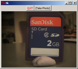
- ov7670_to_pc.jpg (17.21 KiB) Viewed 903 times
I’ve committed the changes I had locally which allow readback of the LCD using Steve’s code plus another function to read RGB24 bit (based on Steve’s code)
I think perhaps I should add Steve’s OV7670 lib that works for me, to the F1 libraries ??
I will tidy up the code and post it at the weekend
PS also making a PCB for Blue Pill + OV767 + LCD
But I keep changing my mind about whether it also needs to connect to the SD pins or the touch screen pins on the LCD board
I think I will have to remove the part of the board that connects to the SD pins because it makes the board too large and costly.
So I will need to do a bit of redesign.
http://stm32duino.com/viewtopic.php?f=1 … 260#p33895
using the connections described in the successive post if you have the same display.
[konczakp – Mon Nov 13, 2017 9:24 am] –
i bet that You forgot about me? Or maybe You posted it somewhere else then here https://github.com/rogerclarkmelbourne/ … /libraries ?
Can’t you just add Steve’s library to your Arduino Library folder ?
I tried to get my camera and display working today, but found a load of wires broke off after I took it along to a Arduino club to show them some things you can do with an STM32.
So it took me a while to work out where all the wires went and to sold them all on again (about 6 wires broke off the display )
This is the code I’m using.
- live_ov7670.zip
- (23.94 KiB) Downloaded 97 times
but it is not working with my blue pill (STM32F103C8T6) and OV7670 non-FIFO.
I can upload the sketch and run it but the Serial Monitor always stop on “Configuring camera…”
It is on Cam_Init() on pid = rdReg(REG_PID);
Here is the Pin connections:
OV7670 STM32F103C8T6
1. Vcc 3.3V
2. GND GND
3. SCL PB6
4. SDA PB7
5. Vsync PB4 (in)
6. Href PB5 (in)
7. Pclk PB3 (in)
8. Xclk PB0 (out)
9. D7..D0 PA7..PA0 (in)
10. Reset Not connected
11. Pwdn Not connected
May be the Reset and Pwdn pins should be connected somewhere or the SCL and SDA need external pull up
or the code is expired (it is from 2015) or my module is broken.
Please help.
4.7k/5.1k to 5v
rumour has it that 10k or below will work
srp
Is my bluepill PB3 broken or is there a problem with PB3 ?
so you need to add
disableDebugPorts();
Unluckily disableDebugPorts(); does lock out further stlink uploads unless i reset the bluepill every time.
2 wire as it says pa13/pa14
3 wire ‘trace async’ adds pb3
4 wire adds pa15 to above
5 wire adds pb4 to above
i don’t suppose you’ve enabled trace async mode as it clobbers pb3 ?
are you using a 20way cable st-link as opposed to a usb stick one(sdclk/sdio/gnd)
might be worth a try – if you add a ‘quit’ button capture inside of the loop function and something akin to
if (buttonpress == true){

EnableDebugPorts();

while(1) {}

}
No idea what that is. Yes, im using an usb-stick, 4 wires including power.
Pressing reset while starting stlink upload works with debugport disabled.
I did simply leave pixclock on PB8 instead of PB3. 2 lines of code change.
Then i finally got the maple bootloader working and now i use it instead of stlink.
I also changed the code so it doesent block waiting for pixclock or href. A little slower than the blocking “while” but safer.
while( VSYNC ); //wait for low

line = 0;

noInterrupts();

while (!VSYNC)	// as long as high

{

if(HREF)

{

if (was_href_lo)

{

was_href_lo = false; // linesync

pck = 0;

line++;

}

if (PCLK)

{

if (was_pix_lo)

{

was_pix_lo = false;

if ( pck&0x01 && line<BUF_SIZE_X ) buf[line][pck>>1] = CAM_DATA;

pck++;

}

}

else was_pix_lo = true;

}

else was_href_lo = true;

}

interrupts();
Serial.println("> image acquisition done.");
trace async – i think provides some info allowing you to follow the program flow.
istr that there’s a hardware mod around for the 10pin usb stick blocks allowing it’s use.
it’s also the first of the options to use PB3, that’s messing you up.
what’s your setup etc ?
just for fun, could you try that suggestion for an exit via an enabling call to enabledebugports ?
srp

> an exit via an enabling call to enabledebugports
The disable works. The enable is not needed, i dont have a button and i stored away the stlink ![]()
more like os win/linux/mac, arduino version, which core and more of a similar ilk
srp
The stm32f103 has 20kb of sram, not enough for 160×120. I might have to use 80×64 or even lower to run a jpeg compressor on it. I did not find a arduino ide compilable jpeg compressor yet. The idea is to have the decompressor on win7 PC and display picture there.
I have the arduino uno version of this with serial comm to PC and a “processing” program to display the BMP picture. AVR code is different, no internal storage of picture due to 2kb sram.
In the future this should migrate to the esp32 and send live realtime compressed pictures in broadcast mode. This might then be used as FPV feed in an RC plane or quad. Video from plane to user, RC data from user to plane, bidirectional.
They do 10km here with hi gain antenna. Camera is the jpeg capable ov2640 (i dont have):
https://www.youtube.com/watch?v=yCLb2eItDyE
Is the single byte “Serial.write(byte)” slow or what is happening?
Has anyone tested the OV2640 cam with build in jpeg compressor?
160×80 BW frame:

EDIT:
I did try to write one whole whole line to serial and its much faster. “Serial.write(linebuf,linesize);”
Using
Serial.write(buffer, nr_bytes);I changed to write a whole line with one write and its much much faster now.
Any help with a jpeg compressor?
dispcam is the display program, processing source. Uses 255 as start frame, 254 start of line, 253 end of pic. pixel values are truncated 0 to 250. You have to click dispcam to start a frame grab.
Note i did change PCLK_PIN to PB8 instead of PB3
If you have a display connected .e.g ILI9341 you can use it as frame store, albeit reading the data out not that fast
I have been developing a machinevision project with ov7670 and bluepill. I have succesfully used stevstrongs original polled version (thanks!). I decided to try dma-version to achieve higher framerate. However i struggle to understand the way dma-reading stores the pixels and how to access them. I try to save for example 80×80 blackscale image(YUV) or color image in uint8_t 2d-buffer. I use QQVGA and 7,5hz fps.
Could somebody plese help to understand it? I have spent lot of time trying to figure out it myself but this is a little beyond me.
1. why data is saved in array
uint8_t pixBuf[2][PIXEL_BUFFER_LENGTH];
I assume that the SW uses a double-buffer acquisition, that is why the array is two dimensional. While the DMA fills one buffer, the other one can be processed: read out, sent to LCD, or stored.
But be aware that the processing should be as fast as possible, processing one frame should be finished before the other is stored in buffer by the DMA.
Your copy routine looks like very time consuming, that can be the reason why it hangs.
The next line will be stored after the pixels are processed.
The reason for this is that the DMA for storing the camera data may not be disturbed with other DMA process.
Now, your piece of code is inside the while(line_counter–) loop.
This means that you should store only one line in buf.
Try something like:
   for(uint8_t i = 0; i<80; i++)

{

buf[screen_h-line_counter-1][i]=*ptr++;

}
buf_ptr = &buf;
However, I wasn’t able to read frames to buffer with this code either. I did some testing and got some strange results. Program froze if i tried to copy any data to another buffer, even if it wasn’t pixBuf used by DMA-funcitons. Same copy routines were behaving normally in other parts of program. I’ll attach one of my test codes.
I think the problem isn’t timing because code doesn’t get stuck even if i add different delays to image-capturing loop, it works normally with short delays and just slows down with longer delays.
If i got it right, acording to datasheet there should be enough time to copy data to buffer. I For example copying 320 bytes took 86uS. Datasheet says that with QVGA fps 15 (12mhz pclk) there is about 42,6uS gap between two lines. (actually ov7725 datasheet, because ov7670 datasheet shows only vga timing but it seems to be same) With lower pclk and QQVGA there should be even more time.
I have to maybe dig into indreks code and try get it working. Or just try to be happy with very low framerate. Good side of low framerate is that it is possible to do some processing between lines, bad side is that if next frame start is missed because of processing it takes long to wait next one.
I probably need to glue the Blue Pill and the camera to a board and rewrite, but there are lots of wires, and I don’t have time to do it at the moment.
Btw.
I did start to make a PCB design for this, but I never finished that either ![]()
https://github.com/stevstrong/LiveOV7670_STM32
However it will not compile and I get following error:
https://github.com/stevstrong/LiveOV7670_STM32/issues/1
Any help appreciated. Am I using wrong project code? The github seems to have DMA working which I am interested in. Or is 320×240@15fps possible without DMA too?
I got the STM32F103 version working somehow from your github repo. I use prescaler=2 and probably get around those 14.6 fps. I get a rainbow colored stripes at the top and right of the display (both about 20 pixels wide) but otherwise the picture is ok.
I wonder what the following code is for in the .ino file – the outer loop triggers every 4th frame and the inner every 128th frame. If I comment it out I get completely black picture. Can you tell what is this code good for?
if ( (loop_counter&(BIT2-1))==0 ) {

if  ( (loop_counter&(BIT7-1))==0 ) {

Serial.write('\n');

}

Serial.write('.');

}
I moved your post here, this is the place to discuss the F1 version.
The code part you pointed out is just a live ticker to usb serial to check whether the code runs or hangs.
Hm, i may need to retest the code, i evetually found a better way to setup the timer to trigger the dma.
I read in the other (F4) thread it should be possible to skip the dma transfer to heap and directly write from camera to SPI – do you mean this enhancement? How much can it make things faster?
For example, it outputs lines 1..30, and then no more pixel data till next Vsync.
That is why the direct data transfer to SPI is tricky, in these cases one have to reinit the window where to write the data to TFT buffer.
But i meant a different timer setting which can maybe improve the DMA trigger speed. Now the timer is set to reset mode, but i experimented lately with external trigger setting which may give better result.
The only prescaler working for me is 2 (image has only minor problems on 2 sides). Are other prescalers also supposed to work? With prescaler=2 the PCLK is 12 MHz – is that right? (XCLK = 24 MHz)
When I set the prescaler to 1, I get about 20% of the image somewhat correct (bad colors, but contents are real) and the rest is rainbow stripes. My guess is that the PCLK timer (TIMER2) keeps up but the SPI to display is overloaded. I know the SPI transfer rate is maxed out with prescaler=2 so this is to be expected.
BTW, does TIMER2 really run at full 72 MHz? The internal led flashes about twice as fast which would indicate some 30 fps going from the camera.
I really have to try the direct DMA from camera to SPI, when I have some time…

