I’m not sure if this is the correct place to post it, but I’m encountering a bug when I program my STM32 with Arduino using the STM32 core, using STLink. Here is my code:
/*

Blink
Turns an LED on for one second, then off for one second, repeatedly.
Most Arduinos have an on-board LED you can control. On the UNO, MEGA and ZERO
it is attached to digital pin 13, on MKR1000 on pin 6. LED_BUILTIN is set to
the correct LED pin independent of which board is used.
If you want to know what pin the on-board LED is connected to on your Arduino
model, check the Technical Specs of your board at:
https://www.arduino.cc/en/Main/Products
modified 8 May 2014
by Scott Fitzgerald
modified 2 Sep 2016
by Arturo Guadalupi
modified 8 Sep 2016
by Colby Newman
This example code is in the public domain.
http://www.arduino.cc/en/Tutorial/Blink
*/
// the setup function runs once when you press reset or power the board
void setup() {
// initialize digital pin LED_BUILTIN as an output.
pinMode(LED_BUILTIN, OUTPUT);
Serial.begin(9600);
Serial1.begin(9600);
Serial2.begin(9600);
Serial.println("hi");
Serial1.println("hi");
Serial2.println("hi");
}
// the loop function runs over and over again forever
void loop() {
digitalWrite(LED_BUILTIN, HIGH); // turn the LED on (HIGH is the voltage level)
delay(1000); // wait for a second
digitalWrite(LED_BUILTIN, LOW); // turn the LED off by making the voltage LOW
delay(1000); // wait for a second
Serial.println("hi");
Serial1.println("hi");
Serial2.println("hi");
}
[ElDominio – Tue Mar 06, 2018 9:03 pm] –
Hey guys,I’m not sure if this is the correct place to post it, but I’m encountering a bug when I program my STM32 with Arduino using the STM32 core, using STLink.
…
All TX pins are pulled high, and there is no output. I checked on a scope and the pulse is constantly held high.
I then tried using the STM8 library with my STM8, and used similar code (since STM8 programs with C), and I could see the pulses in the Tx pin.Any help here? I’ve tried multiple codes with hardware serials and nothing changes, the Tx pins always get pulled high.
Is the STM32F103C8T6 board any of these?
If so, please try using either serial or a boot-loader to load the blink sketch. Let’s first test the board then move on to STLink.
Supported Upload methods: http://wiki.stm32duino.com/index.php?ti … g_a_sketch
Ray
[Pito – Wed Mar 07, 2018 7:25 am] – Does it blink?
It does quite well!
[mrburnette – Wed Mar 07, 2018 1:25 pm] –[ElDominio – Tue Mar 06, 2018 9:03 pm] –
Hey guys,I’m not sure if this is the correct place to post it, but I’m encountering a bug when I program my STM32 with Arduino using the STM32 core, using STLink.
…
All TX pins are pulled high, and there is no output. I checked on a scope and the pulse is constantly held high.
I then tried using the STM8 library with my STM8, and used similar code (since STM8 programs with C), and I could see the pulses in the Tx pin.Any help here? I’ve tried multiple codes with hardware serials and nothing changes, the Tx pins always get pulled high.
Is the STM32F103C8T6 board any of these?
If so, please try using either serial or a boot-loader to load the blink sketch. Let’s first test the board then move on to STLink.
Supported Upload methods: http://wiki.stm32duino.com/index.php?ti … g_a_sketchRay
It’s a STM32F103CBT6, the bluepill one.
I loaded the stm32duino bootloader and uploaded the blink sketch successfully, and the LED blinks, but serial Tx is still being pulled high, tried it on two different boards with the same result. Any more tests you need let me know!
https://www.hackster.io/rayburne/the-qb … tor-ae7015
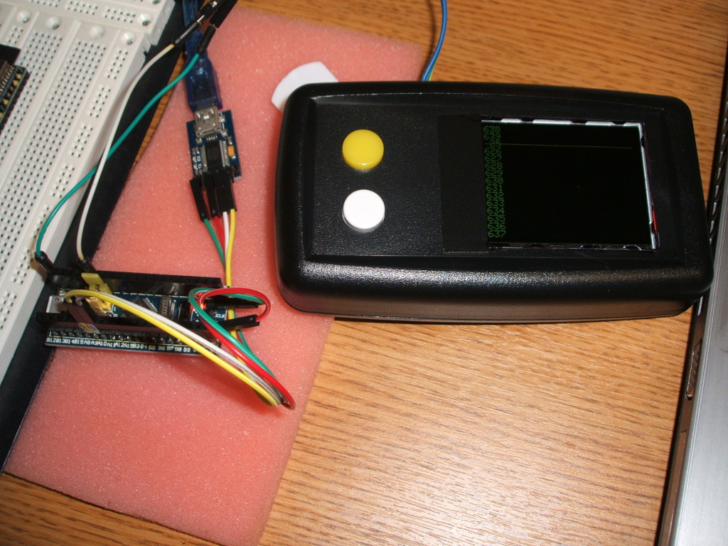
- DSCF2079_web.jpg (229.01 KiB) Viewed 1146 times
[mrburnette – Wed Mar 07, 2018 9:08 pm] –
All: I strongly recommend everyone that works with serial1 or serial2 and does not direct this to the PC via a serial-USB adapter (3.3V) to build something like my QBF … you need it to test.
https://www.hackster.io/rayburne/the-qb … tor-ae7015
DSCF2079_web.jpg
I took one of my Blue Pills.
IDE: 1.8.5 on Linux 18.3 Mint
Generic STM32F103 series, STM32F103CB, 20K SRAM, 128K Flash, Serial, 72MHz (Normal, Smallest (default) on dev/ttyUSB0
USB-Serial: Chinese ST232RL set for 3.3VI tried your sketch. It failed.
I tried my sketch here. It works, that is the LED blinks and Serial is sent through the USB-serial adapter to the console.// moderator edit to remove far too much duplicate copy //
I’ve tried both STMLink upload method and the stm32duino bootloader, and both produce the same results (expect the stm32duino talks through the onboard USB, STLink doesn’t. I have uploaded using STLink with both Arduino IDE and STLink utility, and using the bootloader I uploaded only through Arduino IDE.
Aside from that, I record that all these pins are stuck HIGH with this code:
A2
A9
A12
A15
B4
Obviously, pin C13 goes HIGH with the corresponding LED. This happens on both boards.
[ElDominio – Wed Mar 07, 2018 10:07 pm] –
…
I’ve tried both STMLink upload method and the stm32duino bootloader, and both produce the same results (expect the stm32duino talks through the onboard USB, STLink doesn’t. I have uploaded using STLink with both Arduino IDE and STLink utility, and using the bootloader I uploaded only through Arduino IDE.Aside from that, I record that all these pins are stuck HIGH with this code:
A2
A9
A12
A15
B4Obviously, pin C13 goes HIGH with the corresponding LED. This happens on both boards.
PA9 == Tx1
PA10 == Rx1
PA2 ==Tx2
PB10 == Tx3
- Bluepillpinout.gif (142.14 KiB) Viewed 1130 times
[mrburnette – Wed Mar 07, 2018 10:15 pm] –
…snip
I am not using a simple volt/ohmmeter, I am using a Hantech DSO5102P Digital Oscilloscope, and I have done the same kind of test using my STM8S103F3P6, and I can the the square pulses produced by the serial pins on this board. It’s fine, I’ll figure it out on my own.
[ElDominio – Wed Mar 07, 2018 11:01 pm] –[mrburnette – Wed Mar 07, 2018 10:15 pm] –
…snipI am not using a simple volt/ohmmeter, I am using a Hantech DSO5102P Digital Oscilloscope, and I have done the same kind of test using my STM8S103F3P6, and I can the the square pulses produced by the serial pins on this board. It’s fine, I’ll figure it out on my own.
GeeWhiz, I am not trying to offend you; I’m a hardware geek, I would never call a Hantech DSO5102P a digital VOM on purpose. My only point is my blue pill plus my script outputs serial 9600 BAUD on Tx1, Tx2, and Tx3. The state of any other pin (s) I did not inspect.
Ray
http://stm32duino.com/viewtopic.php?f=28&t=1877#p25002
- The stm32duino bootloader only provides for DFU upload, and does not emulate a com port. The com port will only show up once you upload a sketch.
- After uploading the bootloader with a usb2serial converter or an stlink, it will not be detected as USB Serial port, but as DFU device.
At that point you can use arduino to upload sketches. Once a sketch is uploaded, you will see the Maple serial port detected. - If the sketch crash, the serial may disappear, and the board may not reset itself when trying to upload a sketch. If that happens, just manualy restart the board while uploading and the bootloader will be detected and load the sketch
If so, then Frederik may be able to comment on this.
[stevestrong – Thu Mar 08, 2018 9:28 am] –
Just to make it clear, this is related to the official STM core, and not to Arduino_STM32 (Roger’s) core, right?If so, then Frederik may be able to comment on this.
OMG! Op said:
It’s a STM32F103CBT6, the bluepill one. I loaded the stm32duino bootloader and uploaded the blink sketch successfully, and the LED blinks, but serial Tx is still being pulled high, tried it on two different boards with the same result. Any more tests you need let me know!
Of course, I’m running libmaple with Roger’s core. I never even considered Op would be running with the STM core… even while OP posted in the “STM core” section of the forum because https://github.com/stm32duino/Arduino_C … xt-release states:

- STM Core.png (13.86 KiB) Viewed 299 times
[ElDominio – Tue Mar 06, 2018 9:03 pm] –
Hey guys,I’m not sure if this is the correct place to post it, but I’m encountering a bug when I program my STM32 with Arduino using the STM32 core, using STLink. Here is my code:…
Of course, it still may happen that I misinterpret something.
I’ve just saw this and test sketch from OP.
It’s ok.
Few comment about the sketch:
Serial and Serial1 are the same using PA10/PA9 (Rx/TX)
Serial2 uses PA3/PA2 (Rx/TX)
Serialx –> U(S)ARTx
So Serial1 –> USART1
Serial2 –> USART2
…
Serial is only an alias for better Arduino compatibility. When SerialUSB will be available, Serial could be linked to it.
This will avoid to change all arduino sketch.
So just do this:
Serial.begin(9600);

Serial2.begin(9600);
