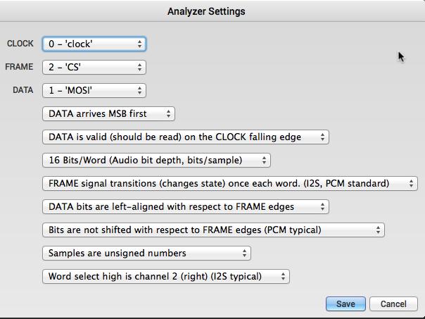
The example sketch produces a 16-bit value Sine wave on the RIGHT Audio channel (PT8211 pin 8) and a SawTooth wave on the LEFT Audio channel (pin 6).
The STM32F103C8T6 is used but can be used on any STM32 with hardware SPI interface. The PT8211 is connected on SPI_1 port.
The example doesn’t include the two’s complement mathematical operation on binary numbers but this is something that can be done easily.
Connections
PT8211 <–> STM32F103
WS <–> PA3
BCK <–> PA5
DIN <–> PA7
/**

I2S example code
Description:
This I2S example creates a Sine waveform on the RIGHT Audio channel of PT8211
and a Sawtooth waveform on the LEFT Audio channel.
This is a very simple how-to-use an external I2S DAC example (DAC = Digital to Analog Converter).
Created on 27 Aug 2015 by Vassilis Serasidis
email: [email protected]
Connections between PT8211 DAC and the STM32F103C8T6
WS <--> PA3
BCK <--> PA5 <--> BOARD_SPI1_SCK_PIN
DIN <--> PA7 <--> BOARD_SPI1_MOSI_PIN
*/
#include <SPI.h>
#define WS PA3
#define BCK PA5
#define DATA PA7
uint16_t hData, lData;
// A full cycle, 16-bit, 2's complement Sine wave lookup table
uint16_t sine_table[256] = {
0x0000, 0x0324, 0x0647, 0x096a, 0x0c8b, 0x0fab, 0x12c8, 0x15e2,
0x18f8, 0x1c0b, 0x1f19, 0x2223, 0x2528, 0x2826, 0x2b1f, 0x2e11,
0x30fb, 0x33de, 0x36ba, 0x398c, 0x3c56, 0x3f17, 0x41ce, 0x447a,
0x471c, 0x49b4, 0x4c3f, 0x4ebf, 0x5133, 0x539b, 0x55f5, 0x5842,
0x5a82, 0x5cb4, 0x5ed7, 0x60ec, 0x62f2, 0x64e8, 0x66cf, 0x68a6,
0x6a6d, 0x6c24, 0x6dca, 0x6f5f, 0x70e2, 0x7255, 0x73b5, 0x7504,
0x7641, 0x776c, 0x7884, 0x798a, 0x7a7d, 0x7b5d, 0x7c29, 0x7ce3,
0x7d8a, 0x7e1d, 0x7e9d, 0x7f09, 0x7f62, 0x7fa7, 0x7fd8, 0x7ff6,
0x7fff, 0x7ff6, 0x7fd8, 0x7fa7, 0x7f62, 0x7f09, 0x7e9d, 0x7e1d,
0x7d8a, 0x7ce3, 0x7c29, 0x7b5d, 0x7a7d, 0x798a, 0x7884, 0x776c,
0x7641, 0x7504, 0x73b5, 0x7255, 0x70e2, 0x6f5f, 0x6dca, 0x6c24,
0x6a6d, 0x68a6, 0x66cf, 0x64e8, 0x62f2, 0x60ec, 0x5ed7, 0x5cb4,
0x5a82, 0x5842, 0x55f5, 0x539b, 0x5133, 0x4ebf, 0x4c3f, 0x49b4,
0x471c, 0x447a, 0x41ce, 0x3f17, 0x3c56, 0x398c, 0x36ba, 0x33de,
0x30fb, 0x2e11, 0x2b1f, 0x2826, 0x2528, 0x2223, 0x1f19, 0x1c0b,
0x18f8, 0x15e2, 0x12c8, 0x0fab, 0x0c8b, 0x096a, 0x0647, 0x0324,
0x0000, 0xfcdc, 0xf9b9, 0xf696, 0xf375, 0xf055, 0xed38, 0xea1e,
0xe708, 0xe3f5, 0xe0e7, 0xdddd, 0xdad8, 0xd7da, 0xd4e1, 0xd1ef,
0xcf05, 0xcc22, 0xc946, 0xc674, 0xc3aa, 0xc0e9, 0xbe32, 0xbb86,
0xb8e4, 0xb64c, 0xb3c1, 0xb141, 0xaecd, 0xac65, 0xaa0b, 0xa7be,
0xa57e, 0xa34c, 0xa129, 0x9f14, 0x9d0e, 0x9b18, 0x9931, 0x975a,
0x9593, 0x93dc, 0x9236, 0x90a1, 0x8f1e, 0x8dab, 0x8c4b, 0x8afc,
0x89bf, 0x8894, 0x877c, 0x8676, 0x8583, 0x84a3, 0x83d7, 0x831d,
0x8276, 0x81e3, 0x8163, 0x80f7, 0x809e, 0x8059, 0x8028, 0x800a,
0x8000, 0x800a, 0x8028, 0x8059, 0x809e, 0x80f7, 0x8163, 0x81e3,
0x8276, 0x831d, 0x83d7, 0x84a3, 0x8583, 0x8676, 0x877c, 0x8894,
0x89bf, 0x8afc, 0x8c4b, 0x8dab, 0x8f1e, 0x90a1, 0x9236, 0x93dc,
0x9593, 0x975a, 0x9931, 0x9b18, 0x9d0e, 0x9f14, 0xa129, 0xa34c,
0xa57e, 0xa7be, 0xaa0b, 0xac65, 0xaecd, 0xb141, 0xb3c1, 0xb64c,
0xb8e4, 0xbb86, 0xbe32, 0xc0e9, 0xc3aa, 0xc674, 0xc946, 0xcc22,
0xcf05, 0xd1ef, 0xd4e1, 0xd7da, 0xdad8, 0xdddd, 0xe0e7, 0xe3f5,
0xe708, 0xea1e, 0xed38, 0xf055, 0xf375, 0xf696, 0xf9b9, 0xfcdc,
};
void setup() {
Serial.begin(19200);
delay(100);
Serial.println("-= I2S Example =-");
// Setup SPI 1
SPI.begin(); //Initialize the SPI_1 port.
SPI.setBitOrder(MSBFIRST); // Set the SPI_1 bit order
SPI.setDataMode(SPI_MODE0); //Set the SPI_2 data mode 0
SPI.setClockDivider(SPI_CLOCK_DIV16); // Slow speed (72 / 16 = 4.5 MHz SPI_1 speed)
pinMode(WS, OUTPUT); //Set the Word Select pin (WS) as output.
}
void loop() {
uint16_t i;
for (i=0;i<256;i++){
lData = sine_table[i];
hData = sine_table[i];
hData >>= 8;
digitalWrite(WS, LOW); //Select RIGHT Audio channel
SPI.transfer(hData); // Data bits 15-8
SPI.transfer(lData); // Data bits 7-0
digitalWrite(WS, HIGH); //Select LEFT Audio channel
SPI.transfer(i); //
SPI.transfer(0); //
}
}
Thank you very much!
I soldered two another of my (guess about 50+ pcs) PT8211’s:
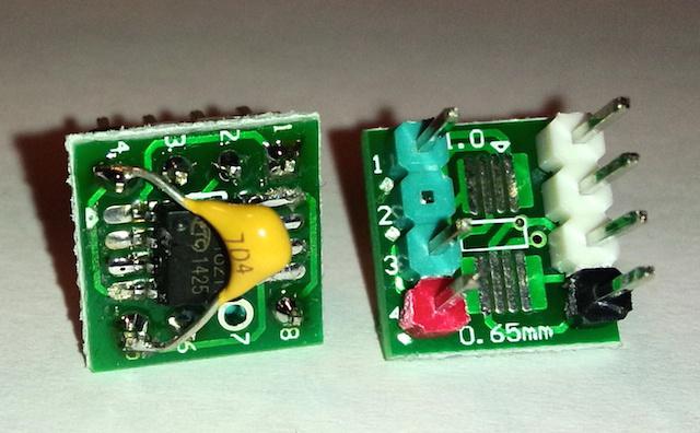
And the result: It’s working!
Maybe if we cannot get the “real I2s” working, this could be a workaround. Just setting the SPI write routines on a timer, some phase accumulators for each voice combined with my USB-MIDI-branch (or normally serial MIDI – the standard lib works great) and ready is the basic synth
So with 2 SPI we can get 4 independent outputs (for analog filters)
Something different: Has somebody got SPI3 working on any device? I see in the board.h file, that there are some troubles
* Note:
* SPI3 is unusable due to pin 43 (PB4) and NRST tie-together ![]() , but
, but
* leave the definitions so as not to clutter things up. This is only
* OK since RET6 Ed. is specifically advertised as a beta board. */
Is this an actual entry (I guess no, because everything we have done, we have signed with our names)
Fact is, even with the new SPI library example, SPI3 wont work for me.
Some updates to real I2S:
I’ve merged again some of the mubase code https://github.com/mubase/STM32F4-Ardui … m32f4codec
but I wont get even a simple master clock out of my MCU….maybe there are too much register differences between F4 and F1…
With this sketch the demo is modified for playing a Waldorf-Format wavetable: 64 tables, each table with 128 entries.
It plays the sound “zero” with different speeds.
Have fun!
For experts:
I make my wavetables with the program “audio-term” https://www.youtube.com/watch?v=cPSjMORs39o
With the output of the program (standard Waldorf Blofeld wavetable format) I wrote my own processing sketch to translate and exclude the audio data from the sysex file (this drove me nuts: raw signed 21bit audio format and much more pitfalls, but I’ve done it ![]() )
)
I got me in your bandwagon, I’ve just ordered some PT8211 on eBay !
There are so cheap !
Thank you very much!
I soldered two another of my (guess about 50+ pcs) PT8211’s:
And the result: It’s working!
Maybe if we cannot get the “real I2s” working, this could be a workaround. Just setting the SPI write routines on a timer, some phase accumulators for each voice combined with my USB-MIDI-branch (or normally serial MIDI – the standard lib works great) and ready is the basic synth
So with 2 SPI we can get 4 independent outputs (for analog filters)
Something different: Has somebody got SPI3 working on any device? I see in the board.h file, that there are some troubles
* Note:
* SPI3 is unusable due to pin 43 (PB4) and NRST tie-together ![]() , but
, but
* leave the definitions so as not to clutter things up. This is only
* OK since RET6 Ed. is specifically advertised as a beta board. */
Is this an actual entry (I guess no, because everything we have done, we have signed with our names)
Fact is, even with the new SPI library example, SPI3 wont work for me.
Some updates to real I2S:
I’ve merged again some of the mubase code https://github.com/mubase/STM32F4-Ardui … m32f4codec
but I wont get even a simple master clock out of my MCU….maybe there are too much register differences between F4 and F1…
SPI3: Is now working, see thread: viewtopic.php?f=3&t=521
Following things I’ve implemented:
16Bit data transfer (remember that SPI.setDataSize must be the last SPI config line
setting up the whole sound engine on timer3 (same timer as DMA 1 SPI1_TX)
The DMA stuff is totally new to me, I’ve to think and learn about it…. but must be easily to be implemented in the new code below
/**

I2S example code (modified by Matthias Diro: 16bit transfer, setting up on timer3)
Description:
This I2S example creates a Sine waveform on the RIGHT Audio channel of PT8211
and a Sawtooth waveform on the LEFT Audio channel.
This is a very simple how-to-use an external I2S DAC example (DAC = Digital to Analog Converter).
Created on 27 Aug 2015 by Vassilis Serasidis
email: [email protected]
Connections between PT8211 DAC and the STM32F103C8T6
WS <--> PA3
BCK <--> PA5 <--> BOARD_SPI1_SCK_PIN
DIN <--> PA7 <--> BOARD_SPI1_MOSI_PIN
*/
#include <SPI.h>
#define WS PA3
#define BCK PA5
#define DATA PA7
// A full cycle, 16-bit, 2's complement Sine wave lookup table
uint16_t sine_table[256] = {
0x0000, 0x0324, 0x0647, 0x096a, 0x0c8b, 0x0fab, 0x12c8, 0x15e2,
0x18f8, 0x1c0b, 0x1f19, 0x2223, 0x2528, 0x2826, 0x2b1f, 0x2e11,
0x30fb, 0x33de, 0x36ba, 0x398c, 0x3c56, 0x3f17, 0x41ce, 0x447a,
0x471c, 0x49b4, 0x4c3f, 0x4ebf, 0x5133, 0x539b, 0x55f5, 0x5842,
0x5a82, 0x5cb4, 0x5ed7, 0x60ec, 0x62f2, 0x64e8, 0x66cf, 0x68a6,
0x6a6d, 0x6c24, 0x6dca, 0x6f5f, 0x70e2, 0x7255, 0x73b5, 0x7504,
0x7641, 0x776c, 0x7884, 0x798a, 0x7a7d, 0x7b5d, 0x7c29, 0x7ce3,
0x7d8a, 0x7e1d, 0x7e9d, 0x7f09, 0x7f62, 0x7fa7, 0x7fd8, 0x7ff6,
0x7fff, 0x7ff6, 0x7fd8, 0x7fa7, 0x7f62, 0x7f09, 0x7e9d, 0x7e1d,
0x7d8a, 0x7ce3, 0x7c29, 0x7b5d, 0x7a7d, 0x798a, 0x7884, 0x776c,
0x7641, 0x7504, 0x73b5, 0x7255, 0x70e2, 0x6f5f, 0x6dca, 0x6c24,
0x6a6d, 0x68a6, 0x66cf, 0x64e8, 0x62f2, 0x60ec, 0x5ed7, 0x5cb4,
0x5a82, 0x5842, 0x55f5, 0x539b, 0x5133, 0x4ebf, 0x4c3f, 0x49b4,
0x471c, 0x447a, 0x41ce, 0x3f17, 0x3c56, 0x398c, 0x36ba, 0x33de,
0x30fb, 0x2e11, 0x2b1f, 0x2826, 0x2528, 0x2223, 0x1f19, 0x1c0b,
0x18f8, 0x15e2, 0x12c8, 0x0fab, 0x0c8b, 0x096a, 0x0647, 0x0324,
0x0000, 0xfcdc, 0xf9b9, 0xf696, 0xf375, 0xf055, 0xed38, 0xea1e,
0xe708, 0xe3f5, 0xe0e7, 0xdddd, 0xdad8, 0xd7da, 0xd4e1, 0xd1ef,
0xcf05, 0xcc22, 0xc946, 0xc674, 0xc3aa, 0xc0e9, 0xbe32, 0xbb86,
0xb8e4, 0xb64c, 0xb3c1, 0xb141, 0xaecd, 0xac65, 0xaa0b, 0xa7be,
0xa57e, 0xa34c, 0xa129, 0x9f14, 0x9d0e, 0x9b18, 0x9931, 0x975a,
0x9593, 0x93dc, 0x9236, 0x90a1, 0x8f1e, 0x8dab, 0x8c4b, 0x8afc,
0x89bf, 0x8894, 0x877c, 0x8676, 0x8583, 0x84a3, 0x83d7, 0x831d,
0x8276, 0x81e3, 0x8163, 0x80f7, 0x809e, 0x8059, 0x8028, 0x800a,
0x8000, 0x800a, 0x8028, 0x8059, 0x809e, 0x80f7, 0x8163, 0x81e3,
0x8276, 0x831d, 0x83d7, 0x84a3, 0x8583, 0x8676, 0x877c, 0x8894,
0x89bf, 0x8afc, 0x8c4b, 0x8dab, 0x8f1e, 0x90a1, 0x9236, 0x93dc,
0x9593, 0x975a, 0x9931, 0x9b18, 0x9d0e, 0x9f14, 0xa129, 0xa34c,
0xa57e, 0xa7be, 0xaa0b, 0xac65, 0xaecd, 0xb141, 0xb3c1, 0xb64c,
0xb8e4, 0xbb86, 0xbe32, 0xc0e9, 0xc3aa, 0xc674, 0xc946, 0xcc22,
0xcf05, 0xd1ef, 0xd4e1, 0xd7da, 0xdad8, 0xdddd, 0xe0e7, 0xe3f5,
0xe708, 0xea1e, 0xed38, 0xf055, 0xf375, 0xf696, 0xf9b9, 0xfcdc,
};
HardwareTimer timer(3);
void setup() {
SPI.begin(); //Initialize the SPI_1 port.
SPI.setBitOrder(MSBFIRST); // Set the SPI_1 bit order
SPI.setDataMode(SPI_MODE0); //Set the SPI_2 data mode 0
SPI.setClockDivider(SPI_CLOCK_DIV4); // speed (72 / 4 = 18 MHz SPI_1 speed) PT8211 up to 20MHZ clock
pinMode(WS, OUTPUT); //Set the Word Select pin (WS) as output.
SPI.setDataSize (SPI_CR1_DFF); // setting SPI data size to 16Bit
// timer3 setup
timer.pause(); // Pause the timer while we're configuring it
timer.setPeriod(1); // // Set up period in microseconds
timer.setChannel1Mode(TIMER_OUTPUT_COMPARE); // Set up an interrupt on channel 1
timer.setCompare(TIMER_CH1, 1); // Interrupt 1 count after each update
timer.attachCompare1Interrupt(timer3_irq);
timer.refresh(); // Refresh the timer's count, prescale, and overflow
timer.resume(); // Start the timer counting
}
byte counter=0;
void loop() {
}
void timer3_irq(void) {
digitalWrite(WS, LOW); //Select RIGHT Audio channel
SPI.write(sine_table[counter]);
digitalWrite(WS, HIGH); //Select LEFT Audio channel
uint16_t ch2=counter<<8;
SPI.write(ch2);
counter++;
}
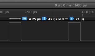
As you can see 4.25us are used from 21us, so the audio routine takes about 20%, maybe this can be better with DMA…
As you can see 4.25us are used from 21us, so the audio routine takes about 20%, maybe this can be better with DMA…
Found a good tutorial for SPI here: http://polplaiconesa.com/tutorials/SPI+DMA.html
The leaflabs wiki is nice written, but without any examples (ok, one usart example). http://wiki.leaflabs.com/index.php?title=DMA
Offtopic: (or not so offtopic…)
Meanwhile I shredded all my 10pcs printed analog-filter boards (from dirty cheap pcb’s) —> too much errors/mistakes (and a complete unrepairable analog switch section) This draws me back at least for an half year for my master project. Ok, I call it “rising learning curve”. All I know is, that I will never use the silly program “fritzing” anymore. I’m now on Kicad and it looks like as a really alternative for eagle. (I cannot use eagle free license, because I need 100×100 and not only 80×100..)
But there are good news to myself: At the beginning I planned to use a STM32 MCU only for controlling my synth (TFT, encoder, knobs, USB-MIDI) and as audio-unit-MCU a PIC32MX250. Drawback: two different territories and upload methods in the final product. Meanwhile I’ll take a bigger STM32 MCU (RET,VET) as a single version for everything. (2x SPI/I2s=4 ind. 16-bit voice outputs, 1x SPI for the rest: TFT, ext. control DAC’s like LT1665,…) Drawback is the lack of a FPU unit in the STMF1 series. I’ve done benchmark tests and every test says: “AVOID float for every costs!”. Ok, I have learned to use fix point arithmetic’s….maybe in one or two years I’ll on STM32F7.
The picture shows a dummy pin, I set it up high on output-routine start and low on the end. So I got the 20% usage. This also helps me finding the right tuning frequency: 47,62 kHz in my example (instead of 48khz..).
Found a good tutorial for SPI here: http://polplaiconesa.com/tutorials/SPI+DMA.html
The leaflabs wiki is nice written, but without any examples (ok, one usart example). http://wiki.leaflabs.com/index.php?title=DMA
Offtopic: (or not so offtopic…)
Meanwhile I shredded all my 10pcs printed analog-filter boards (from dirty cheap pcb’s) —> too much errors/mistakes (and a complete unrepairable analog switch section) This draws me back at least for an half year for my master project. Ok, I call it “rising learning curve”. All I know is, that I will never use the silly program “fritzing” anymore. I’m now on Kicad and it looks like as a really alternative for eagle. (I cannot use eagle free license, because I need 100×100 and not only 80×100..)
But there are good news to myself: At the beginning I planned to use a STM32 MCU only for controlling my synth (TFT, encoder, knobs, USB-MIDI) and as audio-unit-MCU a PIC32MX250. Drawback: two different territories and upload methods in the final product. Meanwhile I’ll take a bigger STM32 MCU (RET,VET) as a single version for everything. (2x SPI/I2s=4 ind. 16-bit voice outputs, 1x SPI for the rest: TFT, ext. control DAC’s,…) Drawback is the lack of a FPU unit in the STMF1 series. I’ve done benchmark tests and every test says: “AVOID float for every costs!”. Ok, I have learned to use fix point arithmetic’s….maybe in one or two years I’ll on STM32F7.
Meanwhile I’ really loving KICad after knowing the pitfalls it’s really elegant to design a schematic and PCB.
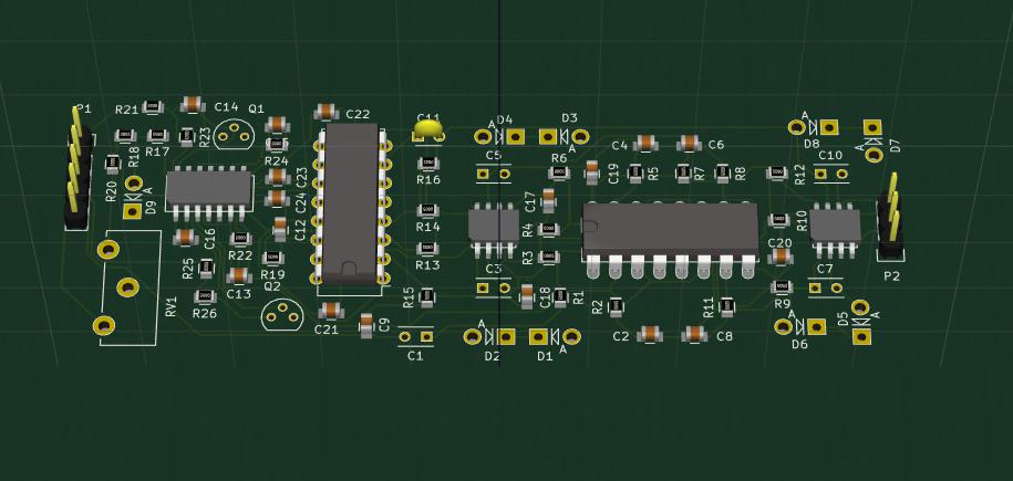
This is my first part of the new analog filter module as 3d render (not all components are set as 3d-models, no time for it).
The 3d modeler is’nt only a eye-catching thing, but it’s really useful finding some minor “haptic” errors.
Meanwhile I’ really loving KICad after knowing the pitfalls it’s really elegant to design a schematic and PCB.
This is my first part of the new analog filter module as 3d render (not all components are set as 3d-models, no time for it).
The 3d modeler is’nt only a eye-catching thing, but it’s really useful finding some minor “haptic” errors.
Personally, I like KiCad more than Eagle, since the PCB footprints are detached from the Part Symbols, it is easier to manage parts with multiple footprints.
I also took the time to write a bunch of (post)scripts that converted my many years of expressPCB designs into KiCad. I even built some 3d models of the microSD cards I was using. expressPCB encrypts the design files, although they do sell gerbers for 50 bucks.
Then KiCad changed the internal file structure and moved the libraries to git. I did download a recent nightly build for mac, will need to do some work to rebuild my libraries so that it can find the 3D models again. The newer 3D viewer is much nicer and allows for better rendering.
Being able to move boards between expressPCB and Kicad is really nice. While it might be a bit pricey I do like the quick turn and easy built into the tool ordering that expressPCB offers or one offs. (which are usually 3 offs)
Because I almost using “exotic” IC’s where are no libs or footprints in kicad (like SSM2164 aka V2164….ok, this one I’d found
sheepdoll: I’m using also Kicad on OSX, with the nightly downloads a clear “no pain” (just one or two settings to make)
Only big drawback: Cloning a bunch of components (like sub-circuits you use 5x, 10x…) isn’t possible (I mean with an updates/synced netlist so you have it in schematics and as – already sorted – footprints on your PCB). There was an script for the old version, but it wont work with newer builds.
A relative new function in kicad:
push and shoves
https://www.youtube.com/watch?v=fdfz_c5Mbrc
got “real” I2S at least on SPI3 working
— -details soon! —
Thanks Matthias.
This was a huge effort to get it working, mostly “mubase” version for stm32f4 helped me out and the STM32F1 reference manual.
I’m not sure how to implement it the best way:
There are many changes in spi.h and spi.c (the core level, lower case not the SPI.c/h library) adding missing config bits and functions. So I must be sensitive for not breaking up them. Maybe the rcc.h needs some entries also (have to proof this).
Next consideration is bringing up the the stuff into the “SPI.c” (upper case – the library) or into a separate “I2S.c” file.
Currently I’m working on an interrupt routine (status: working). The big different between SPI-DAC’s and I2S-DAC’s is, that the I2S device need to feed up with data frequently, even if the value hadn’t changed.
Here I have a common question with interrupts:
Part of my code:
In setup:
spi_irq_enable(SPI3, SPI_TXE_INTERRUPT); This was a huge effort to get it working, mostly “mubase” version for stm32f4 helped me out and the STM32F1 reference manual.
I’m not sure how to implement it the best way:
There are many changes in spi.h and spi.c (the core level, lower case not the SPI.c/h library) adding missing config bits and functions. So I must be sensitive for not breaking up them. Maybe the rcc.h needs some entries also (have to proof this).
Next consideration is bringing up the the stuff into the “SPI.c” (upper case – the library) or into a separate “I2S.c” file.
Currently I’m working on an interrupt routine (status: working). The big different between SPI-DAC’s and I2S-DAC’s is, that the I2S device need to feed up with data frequently, even if the value hadn’t changed.
Here I have a common question with interrupts:
Part of my code:
In setup:
spi_irq_enable(SPI3, SPI_TXE_INTERRUPT); thanks again!
Ok: I deleted enable/disable IRQ within the IRQ itself and it’s working (don’t know what the problem was in a previous of my code so I was setting up this enable/disable IRQ thing – on PIC32 this is a necessary step)
Furthermore your small IRQ code works as expected!
void __irq_spi3(void) {

SPI3_BASE->DR=(transferdata[flip]);

flip=(flip + 1) % buffer_size;

}
In short the flowchart:
I2S in configured to the right frequency for the DAC, so whenever the SPI TX buffer is empty a new value should be written. The value is an array transferdataa[2]: The first one is the left channel value, the second one is the right channel.
In my working example I set up an IRQ which triggers when the SPI buffer is empty. So it sends every even time the left and every odd time the right channel value.
I tried to understand the DMA code within SPI.c, the ili9341 example and furthermore examples not belong to STM32duino, but I wont getting it to work.
So my init code for DMA:
// DMA ********

dma_init(DMA2);

spi_tx_dma_enable(SPI3);

// 6. Setup a DMA transfer (for both TX and RX). If we only want

// write (TX)

// Parameters:

//  - DMA

//  - DMA channel

//  - Memory register for SPI

//  - The size of the SPI memory register

//  - The buffer we want to copy things to or transmit things from

//  - The unit size of that buffer

//  - Flags (see the Maple DMA Wiki page for more info in flags)

dma_setup_transfer(DMA2, DMA_CH2, &SPI3->regs->DR, DMA_SIZE_16BITS,  transferdataa, DMA_SIZE_16BITS, (DMA_MINC_MODE | DMA_TRNS_CMPLT | DMA_TRNS_ERR));
// 7. Attach an interrupt to the transfer. Note that we need to add

// the interrupt flag in step 6 (DMA_TRNS_CMPLT and DMA_TRNS_ERR).

// Also, we only attach it for one of the transfers since they are

// going to finish at the same time because they are in sync.

dma_attach_interrupt(DMA2, DMA_CH2, DMAEvent);
//8. Setup the priority for the DMA transfer.

dma_set_priority(DMA2, DMA_CH2, DMA_PRIORITY_VERY_HIGH);

// dma_set_priority(DMA1, DMA_CH3, DMA_PRIORITY_VERY_HIGH);
// 9. Setup the number of bytes that we are going to transfer.

dma_set_num_transfers(DMA2, DMA_CH2, 2);

//dma_set_num_transfers(DMA1, DMA_CH3, 512);
// 10. Enable DMA to start transmitting. When the transmission

// finishes the event will be triggered and we will jump to

// function DMAEvent.

// dma_enable(DMA2, DMA_CH2);

spi_irq_enable(SPI3, SPI_TXE_INTERRUPT);
The SPI IRQ should be set with a code like “dmasend” (from SPI.c)
uint8 SPIClass::dmaSend(uint8 *transmitBuf, uint16 length, bool minc) {

if (length == 0) return 0;

uint32 flags = ((DMA_MINC_MODE * minc) |  DMA_FROM_MEM | DMA_TRNS_CMPLT);

uint8 b;

dma1_ch3_Active=true;

dma_init(DMA1);

dma_attach_interrupt(DMA1, DMA_CH3, &SPIClass::DMA1_CH3_Event);
// TX

spi_tx_dma_enable(SPI1);

dma_setup_transfer(DMA1, DMA_CH3, &SPI1->regs->DR, DMA_SIZE_8BITS,

transmitBuf, DMA_SIZE_8BITS, flags);// Transmit buffer DMA

dma_set_num_transfers(DMA1, DMA_CH3, length);

dma_enable(DMA1, DMA_CH3);// enable transmit
while (dma1_ch3_Active);

while (spi_is_rx_nonempty(this->spi_d) == 0); // "4. Wait until RXNE=1 ..."

b = spi_rx_reg(this->spi_d); // "... and read the last received data."

while (spi_is_tx_empty(this->spi_d) == 0); // "5. Wait until TXE=1 ..."

while (spi_is_busy(this->spi_d) != 0); // "... and then wait until BSY=0 before disabling the SPI."

dma_disable(DMA1, DMA_CH3);

spi_tx_dma_disable(SPI1);

return b;

}
If you know that your code will not send more data while SPI is still transferring, it is better not wait for completion at all.
One other option is to check / wait for completion of the last transfer before you send a byte to SPI, as this can be more efficient in some circumstances.
Alternatively for DMA, a completion callback could be used instead of waiting. Then you could choose whether to do anything in the SPI DMA complete callback, or perhaps do nothing.
I know I keep mentioning DMA complete callbacks, but I don’t think anyone else but me would use them ![]()
In SPI.c:
/*  Roger Clark and Victor Perez, 2015

*	Performs a DMA SPI send using a TX buffer.

*	On exit TX buffer is not modified.

*	Still in progress.

*/I do not know much about this, but I think that when TX buffer goes from 1 byte to empty then the IRQ request is sent.
After that, while TX buffer is empty, there should not be any more IRQ ?
But I’d need to look in detail and perhaps read the manual to fully understand.
The SPI IRQ should be set with a code like “dmasend” (from SPI.c)
uint8 SPIClass::dmaSend(uint8 *transmitBuf, uint16 length, bool minc) {

if (length == 0) return 0;

uint32 flags = ((DMA_MINC_MODE * minc) |  DMA_FROM_MEM | DMA_TRNS_CMPLT);

uint8 b;

dma1_ch3_Active=true;

dma_init(DMA1);

dma_attach_interrupt(DMA1, DMA_CH3, &SPIClass::DMA1_CH3_Event);
// TX

spi_tx_dma_enable(SPI1);

dma_setup_transfer(DMA1, DMA_CH3, &SPI1->regs->DR, DMA_SIZE_8BITS,

transmitBuf, DMA_SIZE_8BITS, flags);// Transmit buffer DMA

dma_set_num_transfers(DMA1, DMA_CH3, length);

dma_enable(DMA1, DMA_CH3);// enable transmit
while (dma1_ch3_Active);

while (spi_is_rx_nonempty(this->spi_d) == 0); // "4. Wait until RXNE=1 ..."

b = spi_rx_reg(this->spi_d); // "... and read the last received data."

while (spi_is_tx_empty(this->spi_d) == 0); // "5. Wait until TXE=1 ..."

while (spi_is_busy(this->spi_d) != 0); // "... and then wait until BSY=0 before disabling the SPI."

dma_disable(DMA1, DMA_CH3);

spi_tx_dma_disable(SPI1);

return b;

}
I got DMA working (not with the code optimizing stuff from victors post above) The measuring time between led on and of is much longer than in my without-dma-method. So I’ve to work on it.
On question is open (at the beginning on my DMA post):
Should I set the SPI-empty-buffer-irq and this irq is the place for all the DMA stuff? (I did it so with less good results).
In SPI.c:
/*  Roger Clark and Victor Perez, 2015

*	Performs a DMA SPI send using a TX buffer.

*	On exit TX buffer is not modified.

*	Still in progress.

*/DMA is working with the hints from Victor! (both channels: sine left, saw up right)
here is the result from the logic analyzer (led on on IRQ begin, led off on IRQ end):
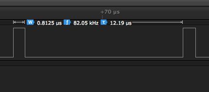
Not bad, isn’t it? ![]()
edit: I think the most used time for this is turning LED on/off ![]()
before setup:
#define buffer_size 2

uint16_t i2s_buffer[2];

uint16_t i2s_buffer_bottom[buffer_size];

uint16_t *i2s_buffer_top_half = &i2s_buffer[buffer_size/2];
before setup:
#define buffer_size 2

uint16_t i2s_buffer[2];

uint16_t i2s_buffer_bottom[buffer_size];

uint16_t *i2s_buffer_top_half = &i2s_buffer[buffer_size/2];
sorry for messing up things!
Now it’s nearly running perfect, only
if ((dma_get_isr_bits( DMA2, DMA_CH2) & 0x2)==1) {

i2s_buffer_top_half[0]= i2s_buffer_bottom[0]+1;

}

else if ((dma_get_isr_bits( DMA2, DMA_CH2) & 0x4)==1) {

i2s_buffer_bottom[0]=i2s_buffer_top_half[0]+1;

}sorry for messing up things!
Now it’s nearly running perfect, only
if ((dma_get_isr_bits( DMA2, DMA_CH2) & 0x2)==1) {

i2s_buffer_top_half[0]= i2s_buffer_bottom[0]+1;

}

else if ((dma_get_isr_bits( DMA2, DMA_CH2) & 0x4)==1) {

i2s_buffer_bottom[0]=i2s_buffer_top_half[0]+1;

}anyway, I got it working with:
void DMAEvent() {

//digitalWrite(LED,1);

if (dma_get_isr_bits( DMA2, DMA_CH2)==3)

{

digitalWrite(LED, 1);

i2s_buffer[0]  = sine[wavecounter1] << 3; // half transfer (10) + complete (01)

wavecounter1++;

}

else

{

i2s_buffer[1] = wavecounter2 << 8;

wavecounter2++;

digitalWrite(LED,0);

}Many code blocks are much the same (pin setup) , but with some differences:
So the I2S init is something like this (example for SPI3):
  rcc_clk_enable(RCC_SPI3);

timer_set_mode(TIMER6, 2, TIMER_DISABLED); // disable every PWM pin!

gpio_set_mode(GPIOA, 15 , GPIO_AF_OUTPUT_PP); // SS pin = WS

gpio_set_mode(GPIOB, 3 , GPIO_AF_OUTPUT_PP); // sck

gpio_set_mode(GPIOB, 4 , GPIO_INPUT_FLOATING); // miso =DO

gpio_set_mode(GPIOB, 5 , GPIO_AF_OUTPUT_PP); // mosi = DI

gpio_set_mode(GPIOC, 7 , GPIO_AF_OUTPUT_PP); // bck if needed!

//SPI3_BASE->I2SPR |= (0x201); // freq setup 44khz, bit 9 = master clock on/off

SPI3_BASE->I2SPR |= 0b0000000100010111; // 48khz master clock off, real: 47.9 khz

// SPI3_BASE->I2SPR |= 0b0000000100011000; // 44.1khz real 42.44 khz!!! master clock off

i2s_peripheral_16_bit_masterx(SPI3); // audio stream setup ---> see below

i2s_init(SPI3); // clock usw... ---> not the same as spi_init(SP3)!!!!!
void i2s_peripheral_16_bit_masterx(spi_dev *dev) {

bb_peri_set_bit(&dev->regs->CR2, SPI_CR2_TXDMAEN_BIT, 1); // DMA enable

//   bb_peri_set_bit(&dev->regs->I2SPR, SPI_I2SPR_MCKOE_BIT, 1);   // turn on_/off mclk

SPI3_BASE->I2SCFGR |= SPI_I2SCFGR_I2SCFG_MASTER_TX; // master xmit

SPI3_BASE->I2SCFGR |= SPI_I2SCFGR_I2SMOD_I2S ;   // i2s mode

SPI3_BASE->I2SCFGR |=  SPI_I2SCFGR_I2SSTD_MSB;   // format --> see "formats"

SPI3_BASE->I2SCFGR |=  SPI_I2SCFGR_DATLEN_16_BIT;    // datalength 16 bit

SPI3_BASE->I2SCFGR |=   SPI_I2SCFGR_CKPOL_LOW;        // cpol low

}

/*

formats

SPI_I2SCFGR_I2SSTD              (0x3 << 4)

#define SPI_I2SCFGR_I2SSTD_PHILLIPS     (0x0 << 4)

#define SPI_I2SCFGR_I2SSTD_MSB          (0x1 << 4)

#define SPI_I2SCFGR_I2SSTD_LSB          (0x2 << 4)

#define SPI_I2SCFGR_I2SSTD_PCM          (0x3 << 4)

*/
The only thing, probably would be good to set a class that can create a different object for SPI2 and SPI3, so a user can use both for i2s if needed.
I can help coding a dma transfer routine to which you can provide the name of the call back function to call as DMA isr, so it would not be blocking as it currenly is in the SPI code.
That way you can use the new library for all the i2s stuff,even setting DMA transfer, and let the ISR to refill the buffer for the sketch.
I need some more ideas of I2s scenarios:
Using as synthesizer (real time audio manipulating) as I do.
Using it as a ultra cheap *wav player (SD-card —> DMA —> I2s)
Maybe audio recording (needs an I2S device with audio in and out) – Problem: inaccurate sampling rate.
Effect board: Audio in —> processing (flanger, delay…) —> audio out. (pretty useless without FPU)
Big question: Can we use a software Mp3, OGG,FLAC de- /encoder on STM32F1? (RAM, speed…)
But I think all scenarios have one thing in common:
There is no need for a “I2s.transfer” or “I2s.send” because I2s needs a permanent data stream solution. So either handling with DMA or with SPI.buffer.empty IRQ (why we should do this, if we have DMA? ![]() ).
).
So with an audio *wav player we can use a big buffer (512B – 1K chunk size) for “real time” we need less (latency)
And ask what they would need / like in a I2S library
Meanwhile I stripped down spi.h / spi.c code to minimum, so only a few changes are necessary.
But I have a big understanding problem:
I use a function to config the right SPI (I2S) device, so SPI2 or SPI3:
void i2s_peripheral_16_bit_masterx(spi_dev *dev) {
transferring:
SPI3_BASE->I2SCFGR |= SPI_I2SCFGR_I2SCFG_MASTER_TX;I2S.begin:
We need at least 7 values!
This are the values:
Value #1= SPI Device (SPI2 or SPI3)
Value #2= I2S configuration mode: Slave – transmit, Slave – receive, Master – transmit, Master – receive
Value #3= I2S standard selection (format): I2S Philips standard, MSB justified standard (left justified), LSB justified standard (right justified), PCM standard
Value #4= Steady state clock polarity, I2S clock steady state is low level, I2S clock steady state is high level
Value #5= Data length to be transferred: 16-bit data length, 24-bit data length, 32-bit data length, Not allowed
Value #6= Channel length (number of bits per audio channel): 16-bit wide, 32-bit wide (only necessary if data length=16 bit)
Value #7= Prescale register with MCK on or off *)
For Value #7 I’ll write some standard definitions, the structure is:
Bit9: Master clock on/of
Bit10: odd or even
Bit 0-7: prescaler
I have a table for that, so I would only define some standard frequencies they work, like 44.1khz, 48khz, 96khz each with master on/off
other values (very specific)
PCM frame synchronization: Short frame synchronization, 1: Long frame synchronization
so the I2S begin function could be:
I2S_begin(spi_device, mode, format, clock_p, data_l, channel_l, prescale)
1) please consider the ST reference manual —> https://www.google.at/url?sa=t&rct=j&q= … kfqCSbMBaw
Chapter 25 “SPI”
2) All the #defines for I2s can be found in “spi.h” (the large one with 18kb)
3) Strange MCK behavior: On my PIC32 in I2S mode the master clock is always running. This is a good thing if you are sync more I2s devices. On STM32 the MCK is only on while transferring data. (confirmed: see last post —> https://my.st.com/public/STe2ecommuniti … views=2585 )
I2S.begin:
We need at least 7 values!
This are the values:
Value #1= SPI Device (SPI2 or SPI3)
Value #2= I2S configuration mode: Slave – transmit, Slave – receive, Master – transmit, Master – receive
Value #3= I2S standard selection (format): I2S Philips standard, MSB justified standard (left justified), LSB justified standard (right justified), PCM standard
Value #4= Steady state clock polarity, I2S clock steady state is low level, I2S clock steady state is high level
Value #5= Data length to be transferred: 16-bit data length, 24-bit data length, 32-bit data length, Not allowed
Value #6= Channel length (number of bits per audio channel): 16-bit wide, 32-bit wide (only necessary if data length=16 bit)
Value #7= Prescale register with MCK on or off *)
For Value #7 I’ll write some standard definitions, the structure is:
Bit9: Master clock on/of
Bit10: odd or even
Bit 0-7: prescaler
I have a table for that, so I would only define some standard frequencies they work, like 44.1khz, 48khz, 96khz each with master on/off
other values (very specific)
PCM frame synchronization: Short frame synchronization, 1: Long frame synchronization
so the I2S begin function could be:
I2S_begin(spi_device, mode, format, clock_p, data_l, channel_l, prescale)
bb_peri_set_bit(&dev->regs->CR2, SPI_CR2_TXDMAEN_BIT, 1); // DMA enable
should not be there.
Yes, sorry, this example is from my test code, I forgot to eliminate the DMA line.
Effect pedal and DUE: I know that stuff: real 12-bit crunchy sound! ![]() Another thing: For uncomplicated effects like simple delay you wont have enough RAM. I read, that the CMSIS DSP library runs not only on M4, but on M3…maybe a good starting point for porting it (I know that on energia/TI – Tiva somebody ported it)
Another thing: For uncomplicated effects like simple delay you wont have enough RAM. I read, that the CMSIS DSP library runs not only on M4, but on M3…maybe a good starting point for porting it (I know that on energia/TI – Tiva somebody ported it)
edit: found it! https://github.com/sumotoy/CMSIS-librar … a-LM4F-mcu
What’s on the left channel?
edit: sine is on the left channel! I messed up my wiring stuff…
if (dma_get_isr_bits( DMA2, DMA_CH2) == 3)i2s_buffer[0]= left channel and
i2s_buffer[1]= right channel
with eleminating the if (dma_get_isr_bits( DMA2, DMA_CH2) == 3) you eleminate the right/left stuff!
I set up a buffer with [2] and the “if” in the function
if (dma_get_isr_bits( DMA2, DMA_CH2) == 3)
triggers every “half transfer finished”. So it fills up on first interrupt the buffer[0]n and on the next buffer[1] But maybe I missed/messed something. But can you use my uncorrected example? Strange, that this is working on my place but not on yours…
void DMAEvent() {

if (dma_get_isr_bits( DMA2, DMA_CH2) == 3)

{

i2s_buffer[0]  = sine[wavecounter1] << 3; // half transfer

wavecounter1++;

flip=1;

}

else

{

i2s_buffer[1] = wavecounter2 << 8 ;

wavecounter2++;

flip=0;
dma_clear_isr_bits(DMA2, DMA_CH2);

digitalWrite(LED,flip);

}
So I proofed that the values are right (I removed the <<8 from the saw up, so it counts only from 0 to 255 and this are the values I got for the channel #1)
A necessary step to get glitch free audio is to insert:
dma_set_priority(DMA2, DMA_CH2, DMA_PRIORITY_VERY_HIGH);Anyway, now it works ok!
I get the rectangle pulse with 47.88 kHz on PD2.
Also I get almost 186Hz * 256 = 47872 samples /second on Sine and Sawtooth waves.
Everything is ok now!
I think the main work is done and from all datasheets, code examples and websites the init code is now very comprehensible.
The big “thank you” goes to victor, who helped me out with DMA and for his patience with me
If done some further tests: Sound stability with the high DMA priority is now perfect, I changed the sine table to 1024 steps (in my last code this can be done very easily) and tested a frequency sweep loop: With 1024 steps there is virtually no antialiasing hearable anymore. Further I got it working with my code that the 440hz reference is REALLY 440hz, amazing.
Vassilis: What are you plans with I2S and what should be in a library (if we need one)?
Tested on:
Arduino IDE 1.6.3, 1.6.4 and 1.6.5
I use the maple mini and from arduino IDE I choose:
Board: “Generic STM32F103C series”
Variant: “STM32F103CB (20k RAM 128k Flash)”
Upload method: “STLink”
After compiling + burning the maple with the “hello_STM” example the blue led started flashing. The example code is not executed ![]()
I would still recommend setting a bigger buffer, at least a few bytes. That will help reduce the overhead a lot, as each ISR call needs something like 15 cycles, and we are doing one per byte sent.
Another option is to remove the half transfer flash, and remove the “if…” sentence in the ISR, and just reload both values in the buffer each time is called.
That will reduce the interrupts to half. The point of having a half transfer interrupt was more for filling larger buffers, there is no advantage with such a small buffer, and a speed disadvantage on servicing interrupts so frequently.
(waveout_A[0] * testvol) / 127)
to
(waveout_A[0] * testvol) / 128)
The compiler should optimize that to a right shift 7 bits, rather than a division that takes a bunch more cycles.
But in general, yeah, the rest is a bit too much for an ISR.
I would use an index to know where I am in the wave portion, and then a buffer of at least 128 bytes, that gives me 64 per channel, 32 words if using 16bits per word, 128 bytes should not leave you out of memory, and would provide a peed up, since I bet calling the ISR causes as much wasted time as calculating one of your output values, big waste.
If you post your whole sketch somewhere I can try turning it to a CoOS example that shows you CPU usage in the corner of a display, if you use a display, or send it thru serialusb if you dont have a display connected, that way you can see how much CPU time you have left for other things, and how much you save with changes.
(waveout_A[0] * testvol) / 127)

to

(waveout_A[0] * testvol) / 128)3On a buffer 256 I have
2459us IDLE time
214,8us IRQ
= 8.034% CPU time
On a buffer 16:
153,6 IDLE
13,5us IRQ
= 8.079% CPU time
So the match winner is: Buffer 16 with better audio quality ![]()
So in this calculation it’s not important how the CPU time for pin manipulation is, because it’s about the relationship between the results. So the main CPU time is calculating the real time audio itself.
Strange thing: (I suspect it, must check it again): On a PIC32MX250 @68MHZ nearly the same code (but without DMA for I2s!) is faster.
So in my final code I suspect to need 10-12% CPU cycle time for each oscillator, so all in all about 40-50% of CPU time, but I need TFT, encoders-knobs-buttons, (USB) MIDI, and more permanent calculations (not on a high frequency as the osc code) like 8x ADSR’s , 8-12x LFO’s and DAC’s (12x) outs to control the external filter board….
On a buffer 256 I have
2459us IDLE time
214,8us IRQ
= 8.034% CPU time
On a buffer 16:
153,6 IDLE
13,5us IRQ
= 8.079% CPU time
So the match winner is: Buffer 16 with better audio quality ![]()
So in this calculation it’s not important how the CPU time for pin manipulation is, because it’s about the relationship between the results. So the main CPU time is calculating the real time audio itself.
Strange thing: (I suspect it, must check it again): On a PIC32MX250 @68MHZ nearly the same code (but without DMA for I2s!) is faster.
So in my final code I suspect to need 10-12% CPU cycle time for each oscillator, so all in all about 40-50% of CPU time, but I need TFT, encoders-knobs-buttons, (USB) MIDI, and more permanent calculations (not on a high frequency as the osc code) like 8x ADSR’s , 8-12x LFO’s and DAC’s (12x) outs to control the external filter board….
Is there something to observe with RTOS (ok, away from using it’s own functions like delay)?
Is RTOS using a specific hardware timer for the tasks?
I’ll read all the functions on http://www.freertos.org/a00019.html
FreeRTOS uses systick with 1khz
FreeRTOS uses systick with 1khz
In the library folder there are two RTOS libs: FreeRTOS and FreeRTOS821. I think the 821 is the newer one that I should use? (Sadly I didn’t found a hint in the forum)
Howto DMA and RTOS-tasks (my consideration):
In the DMA IRQ, which triggers when buffer is empty (I deleted the half empty option) I should set a handler/trigger to an RTOS-task (call it: RTOS_audioengine)
So the RTOS_audinoengine fires up fill up and fill up the buffer?
Should I do that within the DMA IRQ with:
xQueueSendFromISR
xQueueReceiveFromISR ?
edit or
xSemaphoreGiveFromISR
xSemaphoreTake
So the RTOS_audioengine is first priority.
The rest of the tasks should be: TFT (low priority), MIDI (middle-high), human-interface (middle-low), modulations ADSR, LFO’s (middle)….
In the current STM32F1 folder there are two libraries:
“FreeRTOS” this is the old V7.0.1 and
“FreeRTOS821” this is the newest version 8.21
Victor: I found your wav player example at https://github.com/victorpv/Arduino_STM … odule2.ino
In this example you use coos instead of RTOS – why?
edit: Ok, on the first look I feel Coos has the better user manual and looks easier to understand than RTOS
In the library folder there are two RTOS libs: FreeRTOS and FreeRTOS821. I think the 821 is the newer one that I should use? (Sadly I didn’t found a hint in the forum)
Howto DMA and RTOS-tasks (my consideration):
In the DMA IRQ, which triggers when buffer is empty (I deleted the half empty option) I should set a handler/trigger to an RTOS-task (call it: RTOS_audioengine)
So the RTOS_audinoengine fires up fill up and fill up the buffer?
Should I do that within the DMA IRQ with:
xQueueSendFromISR
xQueueReceiveFromISR ?
edit or
xSemaphoreGiveFromISR
xSemaphoreTake
So the RTOS_audioengine is first priority.
The rest of the tasks should be: TFT (low priority), MIDI (middle-high), human-interface (middle-low), modulations ADSR, LFO’s (middle)….
thanks for your inputs!
I’ll play a little bit with Coos and RTOS to get the right “feeling” with it.
As a next step, I’ll design a flow chart of all tasks and the osc-model. Some things are vague to me, like building a LFO:
I’ll use about 8-12 LFO’s (each Voice (4) has 2-3 indepenent LFO’s, so there are LFO_a[4], LFO_b[4] and LFO_c[4].
So I built that on my TIVA with a timer. LFO’s are very simple: Frequency up to 200Hz (or lower), they only scan through a table, like sine[256]. So I gave all of them into a timer_ISR (with for (byte voicenr=0;voicenr<=MAX_VOICES;voicenr++) because the routine is always the same) . For the speed I setup a counter variable (0…256) and the table triggers one step if the counter variable reached the value. With RTOS it might be better to give the LFO function into a separate task or should I build 4 tasks (for each voice) and instead of the counter variable I set up a RTOS_delay… many things to try out
Another thing:
I I occupied this thread so I’ll od further posting on: http://www.stm32duino.com/viewtopic.php?f=19&t=533
I have previously interfaced a Wolfson WM8751 CODEC to a F4 Discovery board for a SDR project. Works great but that was using CMSIS libraries and Eclipse-based IDE.
Now trying now to interface a 320AIC23B CODEC to a Blue Pill using STM32Duino IDE.
I2C is used to configure the CODEC … that works fine, i.e. clock signals appears OK on the scope when the CODEC is initialized. I seem to have some issue related to I2S.
In my setup, the CODEC hardware is MASTER providing BitClock (PA5) and WS (PA3) to the STM32 I2S pins.
It appears PA5 may be configured as output and stays LOW, at least in SLAVE mode.
Am I missing something that needs to be set up besides …
SPI.beginSlave(); //Initialize the SPI_1 port (STM32 is SLAVE).
SPI.setBitOrder(MSBFIRST); // Set the SPI_1 bit order
SPI.setDataMode(SPI_MODE0); //Set the SPI_2 data mode 0
SPI.setClockDivider(SPI_CLOCK_DIV16); // Slow speed (72 / 16 = 4.5 MHz SPI_1 speed)
SPI.setDataSize (SPI_CR1_DFF); // setting SPI data size to 16Bit
Thanks much.
EDIT: Think I found an answer … STM32F103C8T does not have I2S. I’ll have to try something like STM32F103VET6 which as two I2S. Although one can get close to emulate I2S by clever SPI usage, timing becomes tricky … true I2S relies on continuous bit streams. Best to use I2S DMA. Thought I’d share that tidbit.
On the first page is mentioned that PT8211 is using LSBJ (Least Significant Bit Justified) “japanese input format” or some people sid is EIAJ format.
I have TDA1545A, here is datasheet:
http://www.nxp.com/documents/data_sheet/TDA1545A_T.pdf
are that DAC are using same format like PT8211 ?
because I can’t have working configuration for that DAC.
the sound is produced but with much noise.
I also have TDA1543, is I2s version DAC, and it work great using I2S_Standard_Phillips mode.
regards.
TJ
Two things I can recommend:
1) Try out only 8 bit (I’d bought from china some TDA1543 and they are totally fakes and work only with 8-bit, tried it out on more than one system and different audio formats)
2) Try out different Audio formats, sadly I cannot remember where I’ve set the bit for that (just take a quicklook in all those STM32 – I2S guides, it should be easy to find, maybe I’d wrote it into code…)
Yes, it’s hardware issue. The first TDA1545A that I was used is the fake one.
Now I use ooriginal TDA1545A, is working great.
Only 1 issue left for playing 24bit files, I think I need to convert the stream to 16bit first.
about 24 bits to 16 bits:
Why not just:
stream >>= 8;Great project.
If you can help please with suggestion on similar UDA1330ATS Dac chip?
The datasheet says the WS must only change on negative edge of BCK, which of course cannot be exactly so with SPI, after DIN transfer; taking WS high/low – could be any state of clock?
But your chip has same requirement in datasheet timing, and it works!
Also, the ‘Japanese LSB justified’ is amazing clear wording – unlike UDA1330ATS head-scratching confusion. To me anyway.
They are same WS protocol, yes? The L/R data is transferred high speed and then other things can be done before next data transfer?
I want to use the UDA1330ATS on Atmega328 pro mini – need lower sps around 8ksps, therefore interpolating filter essential (10 bit values + dummy data made up to 16 bits).
Many thanks.
- uda1330atsfilterdac.pdf
- (122.78 KiB) Downloaded 65 times
SPI has multiple modes etc. You many want to double check whether you can use it after all
On an oscilloscope, you see the 8 bits as a burst in sync with clock for each byte. Then a gap and then another burst, etc.
But if WS has to go HIGH or LOW to direct data to the correct internal latch of the DAC at the falling clock edge…
Never mind, you seem to have been successful using a big gap at this point in the timing.
I think I can now see why this is so, because the clock has stopped between each byte. And DAC latch has no knowledge or care about this. Well, so long as it isn’t a few hours or days between bytes. The WS state change has still been on the ‘edge’ of the clock, when the stm32 resumes to send the next SPI burst.
In your first example sketch posted. I tried calculating the SPI 4.5mHz clock prescale and your 16 bit words (1 left,1 right).
It takes 1uS to update table position, switch channels,etc. The rest of the time is to SPI.transfer() the 4 bytes?
So for my 8ksps, I need double this rate = 16kHz SPI CLK.
Many thanks, lots of useful info from your posts.
Well, it doesnt work in a way that is normally any use. So we don’t use it.
You’ll have to write code to set and reset the CS line as required.
BTW. If you don’t have more than one device on the SPI, can’t you just leave CS set all the time.
The STM32 has 2 SPI channels, so if you have more than one SPI device, you could put one on SPI1 and one on SPI2 and set the CS on both all the time
I am getting back to work on the stm32 and just ordered some pt8211.
I want to clean up the wav player code and turn it to use one of those.
I am getting back to work on the stm32 and just ordered some pt8211.
I want to clean up the wav player code and turn it to use one of those.
I am getting back to work on the stm32 and just ordered some pt8211.
I want to clean up the wav player code and turn it to use one of those.
I am getting back to work on the stm32 and just ordered some pt8211.
I want to clean up the wav player code and turn it to use one of those.
STM32L4 has a 2 layer implementation, one at the core side, and then layered below on the system side:
https://github.com/GrumpyOldPizza/ardui … /src/I2S.h
https://github.com/GrumpyOldPizza/ardui … rc/I2S.cpp
The class interface is rather straight forward. In essence you just need some DMA based receive/transmit backing it, with a callback for when a transmit/receive is done. The only non-obvious thing in the original interface is that the first receive/transmit bind the direction of the I2S interface …
The internal system layer implementation is a tad more involved for STM32L4, as different voltage ranges and different PLLSAI1/PLLSAI2 usages for STM32L476 and STM32L432/STM32L433 make it somewhat interesting.
Thanks, I have been having a look at both the Arduino and your implementation. Are you using the STM drivers for the lowest level? or you wrote your own?
I’ll see if this coming week I have some time to read how the i2s peripheral works in the F1 and start writing.
I’ll have to ask you some things about the DMA callback functions, but I will when I get to start working on that.
On a side note, I think a similar way of managing the callback should work for the SPI DMA transfers in the F1 core, currently we block instead of using callbacks.
…but I’m really out of business, cause of my second newborn daughter.
As I can remember I didn’t turned the i2s code into a library. All I can remember there was a conversation between us ended up in not using RTOS, but with your DMA examples, that worked flawlessly. I do not know the I2S-zero library, but I guess it’s not really necessary, because getting I2S DMA working is only a few lines of code, so I think it’s better working with “our” code.
Thanks, I have been having a look at both the Arduino and your implementation. Are you using the STM drivers for the lowest level? or you wrote your own?
I’ll see if this coming week I have some time to read how the i2s peripheral works in the F1 and start writing.
I’ll have to ask you some things about the DMA callback functions, but I will when I get to start working on that.
On a side note, I think a similar way of managing the callback should work for the SPI DMA transfers in the F1 core, currently we block instead of using callbacks.
I am getting back to work on the stm32 and just ordered some pt8211.
I want to clean up the wav player code and turn it to use one of those.
I am getting back to work on the stm32 and just ordered some pt8211.
I want to clean up the wav player code and turn it to use one of those.
ArduinoZero (MKRZERO) added a I2S class now that is also supported by a ArduinoSound libary:
https://github.com/arduino/ArduinoCore- … /src/I2S.h
https://www.arduino.cc/en/Reference/I2S
https://www.arduino.cc/en/Reference/ArduinoSound
It might make sense to not reinvent the wheel there and use at least the I2S interface as a base. I discarded my own homegrown interface and added this I2S class to the STM32L4 code. There was only one modification needed to support the MCK output. This STM32 SPI/I2S peripheral would work great with that class interface. N.b. that this “I2S” class is not a kitchensink approach, but the minimum support to get most hardware on the other end of the I2S interface to work.
Looking at all of this, it seems to be best to implement a switch between the I2S.write(sample) and I2S.write(data, size) way, so that the former one needs to check that all DMA has been finished before it could write directly. But then again writing directly is bad, because you cannot prebuffer. Suppose you want to read data from an SD card … I think SAI on STM32L4 has perhaps 16 buffered samples, using the I2S periperipheral on STM32F1 you have only a 1 entry deep buffer.
Size of the buffer. Here is what I did for Uart.h:
    void begin(unsigned long baudrate, uint16_t config);

void begin(unsigned long baudrate, uint16_t config, uint8_t *buffer, size_t size);
size_t I2SClass::write(int32_t sample)

{

if (_state != I2S_STATE_TRANSMIT) {

if (!((_state == I2S_STATE_READY) || (_state == I2S_STATE_TRANSMIT))) {

return 0;

}
_state = I2S_STATE_TRANSMIT;
}
while (!write((const void*)&sample, (_width / 8))) {
armv7m_core_yield();
}
return 1;
}
https://learn.adafruit.com/adafruit-max … mp/pinouts
It is possible to use it with an Arduino Zero
https://www.arduino.cc/en/Tutorial/Ardu … vePlayback
I tried it with the STM32F103 BluePill but it didn’t work. Probably the timing is more critical than with the other I2S DAC proposed here in this thread.
#include <SPI.h>
#define DACSAMPLINGRATE_HZ 16000
#define TIMER_INTTERUPT_US ( 1000000UL / DACSAMPLINGRATE_HZ / 2 ) // division by 2 because of two channels
#define WS PA3
#define BCK PA5
#define DATA PA7
#define testpin PC13
int sine[] = {0x800, 0x832, 0x864, 0x896, 0x8c8, 0x8fa, 0x92c, 0x95e, 0x98f, 0x9c0, 0x9f1, 0xa22, 0xa52, 0xa82, 0xab1, 0xae0,
0xb0f, 0xb3d, 0xb6b, 0xb98, 0xbc5, 0xbf1, 0xc1c, 0xc47, 0xc71, 0xc9a, 0xcc3, 0xceb, 0xd12, 0xd39, 0xd5f, 0xd83,
0xda7, 0xdca, 0xded, 0xe0e, 0xe2e, 0xe4e, 0xe6c, 0xe8a, 0xea6, 0xec1, 0xedc, 0xef5, 0xf0d, 0xf24, 0xf3a, 0xf4f,
0xf63, 0xf76, 0xf87, 0xf98, 0xfa7, 0xfb5, 0xfc2, 0xfcd, 0xfd8, 0xfe1, 0xfe9, 0xff0, 0xff5, 0xff9, 0xffd, 0xffe,
0xfff, 0xffe, 0xffd, 0xff9, 0xff5, 0xff0, 0xfe9, 0xfe1, 0xfd8, 0xfcd, 0xfc2, 0xfb5, 0xfa7, 0xf98, 0xf87, 0xf76,
0xf63, 0xf4f, 0xf3a, 0xf24, 0xf0d, 0xef5, 0xedc, 0xec1, 0xea6, 0xe8a, 0xe6c, 0xe4e, 0xe2e, 0xe0e, 0xded, 0xdca,
0xda7, 0xd83, 0xd5f, 0xd39, 0xd12, 0xceb, 0xcc3, 0xc9a, 0xc71, 0xc47, 0xc1c, 0xbf1, 0xbc5, 0xb98, 0xb6b, 0xb3d,
0xb0f, 0xae0, 0xab1, 0xa82, 0xa52, 0xa22, 0x9f1, 0x9c0, 0x98f, 0x95e, 0x92c, 0x8fa, 0x8c8, 0x896, 0x864, 0x832,
0x800, 0x7cd, 0x79b, 0x769, 0x737, 0x705, 0x6d3, 0x6a1, 0x670, 0x63f, 0x60e, 0x5dd, 0x5ad, 0x57d, 0x54e, 0x51f,
0x4f0, 0x4c2, 0x494, 0x467, 0x43a, 0x40e, 0x3e3, 0x3b8, 0x38e, 0x365, 0x33c, 0x314, 0x2ed, 0x2c6, 0x2a0, 0x27c,
0x258, 0x235, 0x212, 0x1f1, 0x1d1, 0x1b1, 0x193, 0x175, 0x159, 0x13e, 0x123, 0x10a, 0xf2, 0xdb, 0xc5, 0xb0,
0x9c, 0x89, 0x78, 0x67, 0x58, 0x4a, 0x3d, 0x32, 0x27, 0x1e, 0x16, 0xf, 0xa, 0x6, 0x2, 0x1,
0x0, 0x1, 0x2, 0x6, 0xa, 0xf, 0x16, 0x1e, 0x27, 0x32, 0x3d, 0x4a, 0x58, 0x67, 0x78, 0x89,
0x9c, 0xb0, 0xc5, 0xdb, 0xf2, 0x10a, 0x123, 0x13e, 0x159, 0x175, 0x193, 0x1b1, 0x1d1, 0x1f1, 0x212, 0x235,
0x258, 0x27c, 0x2a0, 0x2c6, 0x2ed, 0x314, 0x33c, 0x365, 0x38e, 0x3b8, 0x3e3, 0x40e, 0x43a, 0x467, 0x494, 0x4c2,
0x4f0, 0x51f, 0x54e, 0x57d, 0x5ad, 0x5dd, 0x60e, 0x63f, 0x670, 0x6a1, 0x6d3, 0x705, 0x737, 0x769, 0x79b, 0x7cd,
};
HardwareTimer timer(3);
#define PIN_PORT GPIOC // testpin
#define PIN_PORT1 GPIOA // WS pin
#define PIN_BIT 5
#define PIN_BIT1 3
#define SD_MODE_PIN PB1
void setup() {
pinMode(SD_MODE_PIN, OUTPUT);
digitalWrite(SD_MODE_PIN, LOW); // off
Serial.begin(9600);
delay (500);
SPI.begin(); //Initialize the SPI_1 port.
SPI.setBitOrder(MSBFIRST); // Set the SPI_1 bit order
SPI.setDataMode(SPI_MODE0); //Set the SPI_2 data mode 0
//SPI.setClockDivider(SPI_CLOCK_DIV4); // speed (72 / 4 = 18 MHz SPI_1 speed) PT8211 up to 20MHZ clock
//SPI.setClockDivider(SPI_CLOCK_DIV16); // speed (72 / 4 = 18 MHz SPI_1 speed) PT8211 up to 20MHZ clock
SPI.setClockDivider(SPI_CLOCK_DIV128); // speed (72 / 4 = 18 MHz SPI_1 speed) PT8211 up to 20MHZ clock
//SPI.setClockDivider(SPI_CLOCK_DIV256); // speed (72 / 4 = 18 MHz SPI_1 speed) PT8211 up to 20MHZ clock
pinMode(WS, OUTPUT); //Set the Word Select pin (WS) as output.
pinMode(testpin, OUTPUT);
SPI.setDataSize (SPI_CR1_DFF); // setting SPI data size to 16Bit
// timer3 setup
timer.pause(); // Pause the timer while we're configuring it
timer.setPeriod( TIMER_INTTERUPT_US ); // // Set up period in microseconds
timer.setChannel1Mode(TIMER_OUTPUT_COMPARE); // Set up an interrupt on channel 1
timer.setCompare(TIMER_CH1, 1); // Interrupt 1 count after each update
timer.attachCompare1Interrupt(timer3_irq);
timer.refresh(); // Refresh the timer's count, prescale, and overflow
timer.resume(); // Start the timer counting
delay(1000);
digitalWrite(SD_MODE_PIN, HIGH); // on
while (1);
}
void loop() {
}
void timer3_irq(void)
{
static uint32_t channel = 0;
static uint8_t index = 0;
channel ^= 1;
if (channel)
{
// digitalWrite(WS, LOW); //Select RIGHT Audio channel
gpio_write_bit(PIN_PORT1, PIN_BIT1, LOW);
SPI.write(sine[index++]);
} else
{
// digitalWrite(WS, LOW); //Select LEFT Audio channel
gpio_write_bit(PIN_PORT1, PIN_BIT1, HIGH);
SPI.write(sine[index]);
}
}
// http://www.stm32duino.com/viewtopic.php?f=18&t=519#p5195
/**
I2S example code (modified by Matthias Diro: some sinus melody - 16bit transfer, setting up on timer3)
Description:
This I2S example creates a Sine waveform on the RIGHT Audio channel of PT8211
and a Sawtooth waveform on the LEFT Audio channel.
This is a very simple how-to-use an external I2S DAC example (DAC = Digital to Analog Converter).
Created on 27 Aug 2015 by Vassilis Serasidis
email: [email protected]
Connections between PT8211 DAC and the STM32F103C8T6
WS <--> PA3
BCK <--> PA5 <--> BOARD_SPI1_SCK_PIN
DIN <--> PA7 <--> BOARD_SPI1_MOSI_PIN
*/
The timing of the code example above ( timer interrupt triggers SPI ) seems to be not sufficient for this chip.
The bit sequence needs to start 1 bit delayed ( relating to the I2S specs ) which seems to me that it can not be done with DMA.
The timing of the code example above ( timer interrupt triggers SPI ) seems to be not sufficient for this chip.
The bit sequence needs to start 1 bit delayed ( relating to the I2S specs ) which seems to me that it can not be done with DMA.
Well, yes … but the breakout board from Adafruit is unfortunately the ‘A’ version … and I have it …
https://developer.mbed.org/users/Plugo/ … -adafruit/
Ok, let’s delay the problem for some years ..
Well, yes … but the breakout board from Adafruit is unfortunately the ‘A’ version … and I have it …
https://developer.mbed.org/users/Plugo/ … -adafruit/
Ok, let’s delay the problem for some years ..
Yes, sometimes I also tend to solve software problems by hardware ![]()
Here is a nice one, but it is made for self-soldering:
https://www.pjrc.com/store/pt8211_kit.html
Yes, sometimes I also tend to solve software problems by hardware ![]()
Here is a nice one, but it is made for self-soldering:
https://www.pjrc.com/store/pt8211_kit.html
Is the TP8211 a same kind of DAC as the PCM61P?
I have a hunch it is but I couldn’t confirm that beyond the fact both have a word clock, a bit clock and a single serial data input plus that both are MSB first.
The PCM61P and similar of its kind have LE as word clock, then CLK and DATA.
With the Arduino IDE having board setting we’d still have to know which board to select.
So which board must we select among the plethora of choices?
Are there other directives necessary to make the compilation and upload go successful?
Thanks for helping out.
[victor_pv – Fri Feb 16, 2018 7:07 pm] –
That one has 18bit of resolution vs the 16 bits in the pt8211, so they are not the same or work the same.
Thanks for your reply.
The resolution is indeed different. The EMAX II sampler that I own is 16-bit. Its schematics show a PCM53’s as output DAC’s for the different outputs. However the seats are occupied by AD1860 DAC’s which are 18-bit. The fed bits are alligned as such that the 18-bit DAC behaves the same as the 16-bit DAC when it comes to producing output.
I should have asked if the PT8211 is as such similar to the PCM53 when it comes to the 3 serial data communication pins LE, CLK and DATA and the resulting output.
As far as the PCM61, you should check the datasheet of each and decide for yourself if it fits your applicaton.
If your question is whether you can replace one for the other without software changes the answer I would guess is NO. The PT8211 is a stereo DAC, and has a clk, datain, and WS (world select) that makes the input data go to one channel or the other. It stays high for a whole word, then low for the whole next word, and so on. The PCM61 is a single channel DAC and LE has to go up and down at the end of each word shift.
[Phoebus1966 – Fri Feb 16, 2018 11:07 pm] –[victor_pv – Fri Feb 16, 2018 7:07 pm] –
That one has 18bit of resolution vs the 16 bits in the pt8211, so they are not the same or work the same.Thanks for your reply.
The resolution is indeed different. The EMAX II sampler that I own is 16-bit. Its schematics show a PCM53’s as output DAC’s for the different outputs. However the seats are occupied by AD1860 DAC’s which are 18-bit. The fed bits are alligned as such that the 18-bit DAC behaves the same as the 16-bit DAC when it comes to producing output.I should have asked if the PT8211 is as such similar to the PCM53 when it comes to the 3 serial data communication pins LE, CLK and DATA and the resulting output.
I don’t know if the answer is relevant after one month:
The EMAX II DAC’s are for sure not I2S, but parallel, because it was released in the late 1980ies, far beyond “the birth” of I2s ![]()
The AD1860 are equipped with a “modern” protocol, not sure if I2s or PCM (they are both quiet similar). So there must be different revisions of the EMAX II, for sure started with PCM53 and later with “modern” AD1860 – but they must have a complete different circuit layout. As I can remember there is a STM release note out there for description of the different protocols. (I can’t find it the easy way now).