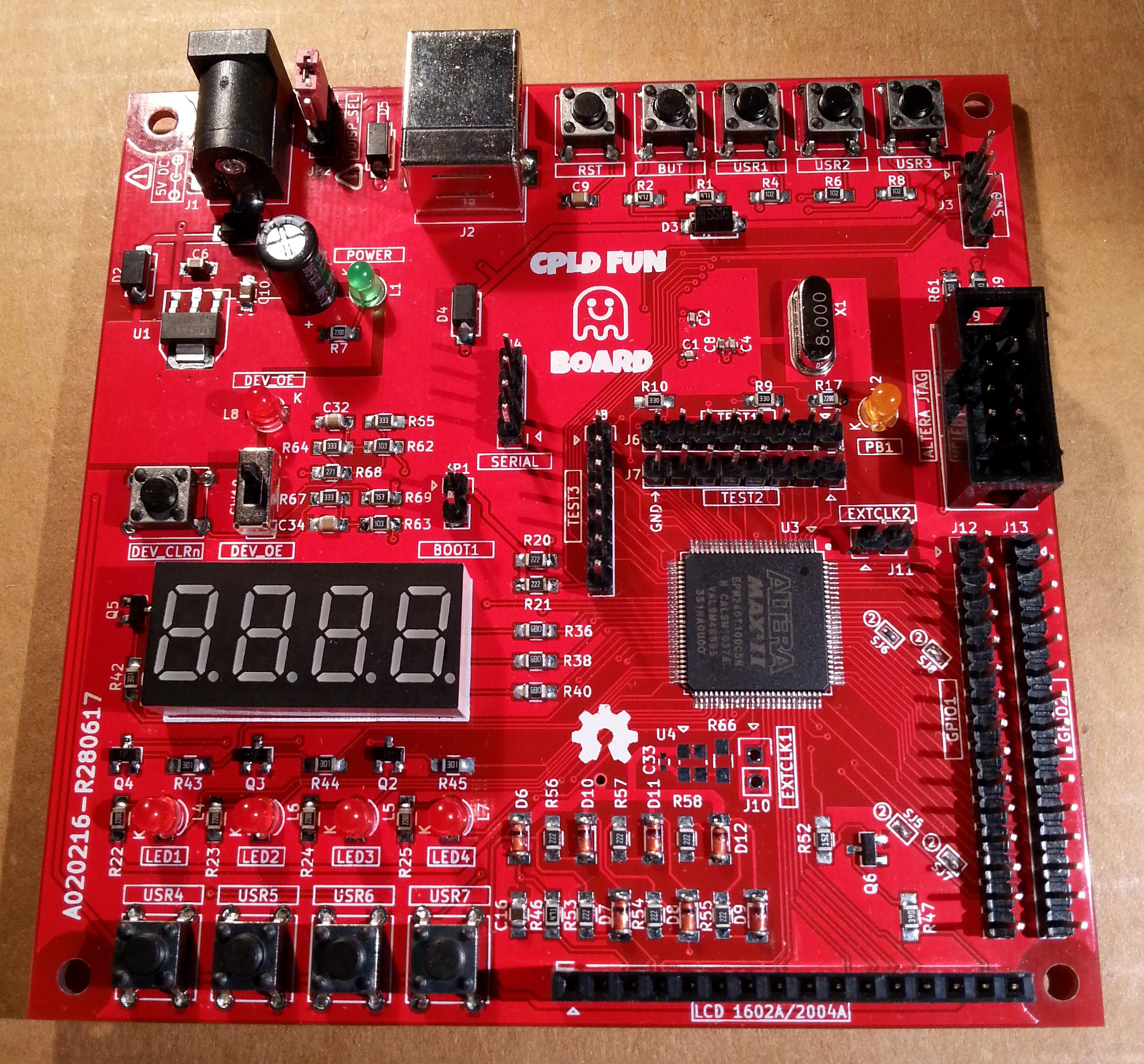
as “promised” here it is the CPLD Fun Board!
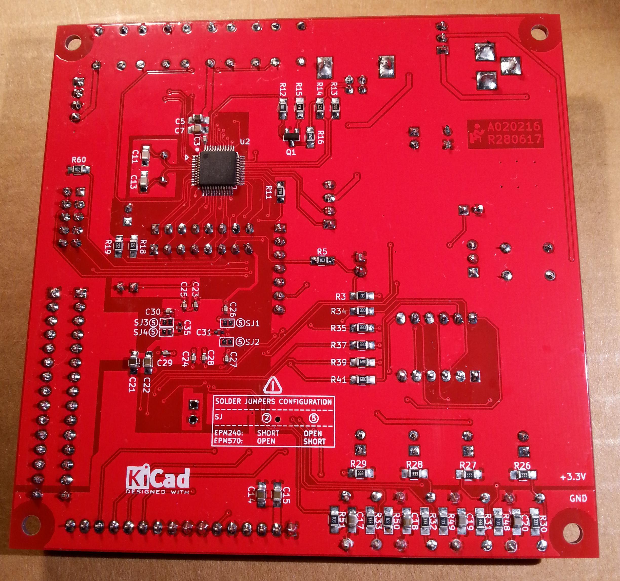
It can be seen as two boards into one: a STM32F103 based Arduino (Maple Mini compatible) and an Altera MAX II CPLD (EPM240T100 or EPM570T100) dev board to start playing with VHDL/Verilog, or just to try to use a CPLD with the Quartus II schematic editor.
The STM32 is used as “stimulus” generator for the CPLD:
Here it is a short demo video:
The cost should be about 5/6$ plus the PCB (I haven’t done the precise BOM calculation yet…), buying the components “around”. The “pluggable” LCD module and the optional stand-alone 50MHz oscillator aren’t included in the cost count.
All the details including the schematic and the PCB Gerber files can be found here.
There is also an article on this board on Hackaday here.
BTW: I’ve just realized that gmail was putting all the notification from this site into the spam folder… ![]()
Cheers.
Probably you should have added a Arduino standard pin out that people could plug in some shields.
About the Arduino standard pinout… hmmm… not sure if having it in this thing it would be useful… hmmm…
Not for now, but next days/weeks I want add some basic VHDL examples here with some examples using the Quartus II schematic editor, using the HW on the board.
But at first I must add how to configure the Quartus II IDE at best for the board…
PS: please don’t consider me a VHDL expert… ![]()
Then I’ll start playing with the next thing… the “FPGA Fun Board”… ![]()
The only possible risk with your design is the smaller cpld is small, and the larger is expensive..
An “SPI” or “I2C” module will most probably not fit into the smaller one, but the simplest interface to the stm32 could be done by serial shift in/out.
For example 32bit may cost you 32 LUTs for in_shiftreg and 32 LUTs for the in_latch. For reading you may need another 32 LUTs for the out_latch and 32 LUTs for out_shiftreg. Instead of the out_shiftreg you may use 32:1 mux with 5 address pins to read out the out_latch. That may save you 32 FFs (the cell is 4bit LUT + 1 FF), as the quartus may reuse the existing out_latch LUTs.. Or, you may use 5bit counter to address the 32bit mux (+5 FFs) thus you save some io pins..
About the EMP570… I found it at about 3.5$ (it’s on the way…)… anyway you are right… it is a bit pricey considering that an entry level FPGA can be found at about 5$ (but you must add the eeprom and “some” regulators too…)
“AN 265: Using Altera MAX Series as Microcontroller I/O Expanders”
https://www.altera.com/documentation/sa … 05644.html
I was selfishly hoping you had already written the mcu code for the STM32 : )
[Rick Kimball – Fri Oct 20, 2017 7:57 pm] –
“AN 265: Using Altera MAX Series as Microcontroller I/O Expanders”
https://www.altera.com/documentation/sa … 05644.html
I read that AN but forget it… ![]() may be an interesting example…
may be an interesting example…

