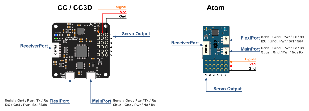
OpenPilot CC3D connection guide
OpenPilot CC3D OpenPilot CopterControl 3D wiring guide with power, signal assignments, and bench checks.
OpenPilot CopterControl 3D
39 contacts Current packagePower the board from USB
RequiredConnect the board to a USB host through its data cable. Leave the accessory power rail and outputs disconnected.
- USB power
- Host VBUS
- VBUS (USB-1)
- USB return
- Host ground
- GND (USB-5)
Bench checks
- Check the board power indicator and host enumeration before attaching a logic probe.
- The USB connection supplies the controller. Connect the external rail only when you have verified the connected accessories and voltage.
OpenPilot CC3D Hardware Setup · Ports and pin-outs · Power
Connection scenarios
Connect a 3.3 V serial adapter
Power the board by USB and configure MainPort for serial operation. Use a 3.3 V logic-level adapter. Cross TX and RX and connect ground. Keep the adapter power lead disconnected.
- Board transmit
- MAIN_TX (MAIN-3)
- Adapter RX
- Board receive
- MAIN_RX (MAIN-4)
- Adapter TX
- Common ground
- GND (MAIN-1)
- Adapter GND
Bench checks
- Check the firmware serial-port mode and baud rate. Run a known serial message and verify its frame timing.
- If no bytes arrive, verify the logic level and ground connection before changing firmware settings.
OpenPilot CC3D Hardware Setup · Ports and pin-outs
OpenPilot CopterControl 3D wiring map
MainPort · JST-SH 4
FlexiPort · JST-SH 4
ReceiverPort · JST-SH 8
USB · CONN4
Servo channel 1
Servo channel 2
Servo channel 3
Servo channel 4
Servo channel 5
Servo channel 6
OUT1-1 · GND
Connect to the board ground return.
Models and documents
Matches the CopterControl 3D open hardware files. Match the key and PCB labels on your board before connecting a harness.
- OpenPilot CopterControl 3D
- Original CC3D PCB with STM32F103 and MPU6000.
- OpenPilot CC3D hardware setup· Connector modes, contact positions and power behavior.
- CopterControl 3D hardware files· Design archive including the schematic and assembly drawings.
- CC3D port drawing· Component-side view of the board connectors.
- Controller-board source register· Manufacturer documents, applicability and SHA-256 digests.