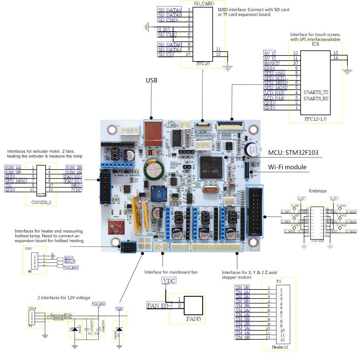
Geeetech GTM32 connection guide
Geeetech GTM32 Geeetech GTM32 wiring guide with power, signal assignments, and bench checks.
Geeetech GTM32
78 contacts Current packagePower only the main electronics
RequiredDisconnect heaters, fans, motors and the bed expansion board. With the bench supply off, match the P3 mating housing and verify continuity of its ground contacts. Use a current-limited 12 V DC bench supply on the main branch.
- Main 12 V
- Bench supply +12 V
- VDC (P3-2)
- Common ground
- Bench supply return
- GND (P3-1)
- GND (P3-4)
Bench checks
- Leave P3-3 open. Verify polarity against the manufacturer diagram before enabling power.
- Verify the regulated 3.3 V endstop supply against ground before connecting the host.
Geeetech GTM32 Board · manufacturer connector circuit drawing · P3 and endstop circuits
Connection scenarios
Identify the USB serial interface
With the controller in the logic-only fixture, attach a standard USB Type-B data cable to a computer.
- USB data minus
- Host D−
- USB_DM (USB-2)
- USB data plus
- Host D+
- USB_DP (USB-3)
- USB return
- Host GND
- GND (USB-4)
Bench checks
- Confirm that the USB serial device enumerates. Select the baud rate from the printer firmware documentation.
- Read the firmware identification with motors and heaters disconnected.
Geeetech GTM32 Board · Interface and USB serial setup
Geeetech GTM32 wiring map
P3 fused 12 V inputs
HB bed expansion header
EXT0 extruder header
Endstop header
HB-3 · BED_T
Temperature signal in the printer harness. Follow the appropriate expansion board or extruder wiring.
Models and documents
Contact numbers follow the original Geeetech circuit drawing. The separate harness illustrations use their own numbering and view. The map covers P3, HB, EXT0, endstops, P2, FAN0, SD, LCD and USB. Confirm any Wi-Fi or other auxiliary connector in its own documentation.
- Geeetech GTM32
- STM32F103VET6 · Separate main and bed 12 V branches.
- Geeetech GTM32 board manual· Original board design and connector resources.
- Geeetech GTM32 connector circuit drawing· Numbered board nets and interface locations.
- Controller-board source register· Manufacturer documents, applicability and SHA-256 digests.