Now I reached a point where my programmings skills lack, so instead of optimizing my code i started to look at maple mini and thought it would be excellent to also add a “nice” GUI to my project.
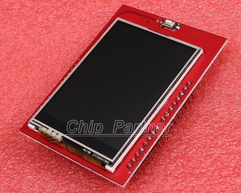
I ended up ordering a chinese 3.2″ tft+touch+sd card combo, but what i didn’t know or think of beforehand was to check the connectivity needed (i just read here and saw all the included libraries for the aforementioned display controller), but all of them are using SPI. So the display came in the mail and i became aware that it didn’t have any SPI interface, (at least not for the display, only for the touch and sd card)
Are there any working options that is available to use with stm32duino? What would be my best chance of getting this to work? (i was initially thinking about going for a MEGA, but choose the maple mini clone as i was impressed with the various tft demos i’ve seen )
I’ve tried looking through “all” of the internet, but have only found small pointers, and none of the really targeted for stm32duino. (i found one post where someone had posted an utft version with support for stm32, which was based on some teensy port, but it was also done for SPI only, and i couldn’t find any ILI9341 tft ‘drivers’ for parallel communication… well there was one for an ILI9481 but i’m not sure if that can be used in direct replacement.
Anyone has a similar display and has it working with a maple mini?
Thanks!
Andreas
The entire forum is indexed by Google, so you can form a query as:
pig scope site:stm32duino.comI believe i have scratched through most of this forum (although I might’ve missed out in some hidden thread). I’ve also visited and examined your projects page as well (which i think was one of the factors that made me want to give the maple mini a ‘go’)
Either way, all the info i’ve found for ILI9341 are with SPI connectivity, which i guess my module lacks (post-sales service from chinese vendors leaves quite a bit to ask for imho). I saw there was an Adafruit library for AVR which had support for SPI and 8bit parallell for ILI9341, but i’m not yet comfortable in the low level details of the stm32 boards to port this).
Wifey’s todo-list and 2 toddlers tends to kill of most of my time as well, so I was hoping that others more low-level-nerdy than me would’ve already taken a look at this. ![]()
pics of back, any identication text, link to the seller/desciption would all be helpful
i suggested a google with ili9341 and pdf, substitute ssd1289 – returns shed loads of links
the chips mode is set by 4 pins same with ssd1289 and i suspect the silk screen might be a one size fits all types/models. as you’ve opened it you might be able to see what its set up for (avo/multimeter resistance pin to ground ) and go from there
next is assume spi and try to read from a register (id-code1/2/3) and see if it makes sense.
you might need to send some values to reset it first.
also the id registers vary from driver to driver:-)
my starting point is the using spi sketch, about to go that route for some of my displays
stephen
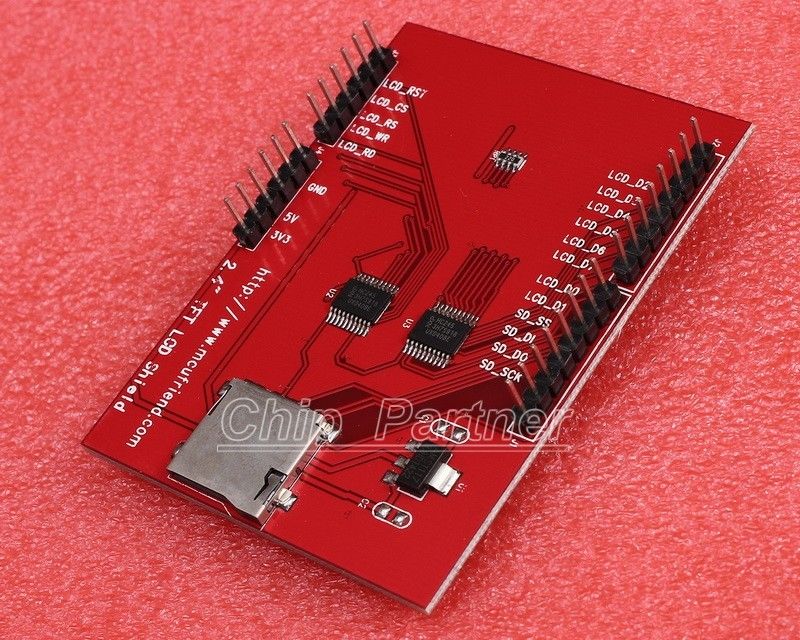
and it looks exactly like this one http://www.sainsmart.com/sainsmart-3-2- … er-reviews but when looking at the back of the pcb my board uses a TSC2046 as a touch screen controller (but that is for later, first step is to actually being able to display something useful on the screen)
On the ‘ribbon’ that connected the display to the pcb it is written T32-1289 V21
I doubt that this display uses spi , of all the 40pins the pcb has, the ones that would point to spi are for the sd-card reader(SD_CLK, SD_DIN etc..) and touch (T_CS, T_CLK etc..) and i guess the DB0-15 and CS, REST, RD, WR, RS are for the actual display in parallel mode?
<…>
I doubt that this display uses spi , of all the 40pins the pcb has, the ones that would point to spi are for the sd-card reader(SD_CLK, SD_DIN etc..) and touch (T_CS, T_CLK etc..) and i guess the DB0-15 and CS, REST, RD, WR, RS are for the actual display in parallel mode?
http://www.wayengineer.com/32-tft-lcd-w … hRl9Orjsgs
at the bottom is a link to a pdf of the display specification, this is before the pcb gets attached.
p12 details the interface as an 8080 parallel type – 16bit data, rd/wr/cs/rs controls & 2.8v power
https://www.raspberrypi.org/forums/view … p?p=307273 yields
http://static.electrodragon.com/wp-cont … play-3.jpg
does this match yours?
ok, its raspberry, but the1rytttttttttttttttt the cat just exercised across the keyboard, she’s peeved she got locked out and it rained.
anyway there’s a circuit in there which might be of interest; 4040 & 3x 4094 to give a spi interface
TSC2046 is likely the TI version of xpt2046 and probably a drop-in replacement
stephen
But let say that I’ve recently ordered an LCD 8 bit Parallel : http://www.ebay.ca/itm/141647130960
I didn’t found library compatible as is, but find pieces of code put together, so here is a part of my sketch using this LCD on my Netduio2Plus :
uint8_t LCD_RST = PC4;

uint8_t LCD_CS = PC3;

uint8_t LCD_RS = PC2;

uint8_t LCD_WR = PC1;

uint8_t LCD_RD = PC0;

uint8_t DPINS[] = {PC7, PC6, PA3, PA2, PB12, PB8, PB9, PA1, PA0, PA6};
#define Black 0x0000
#define White 0xFFFF
#define Red 0xF800
#define Green 0x07E0
#define Blue 0x102E
#define Cyan 0x07FF
#define Magenta 0xF81F
#define Navy 0x000F
#define DarkGreen 0x03E0
#define Purple 0x780F
#define Olive 0x7BE0
#define DarkGrey 0x7BEF
#define DarkCyan 0x001F
#define Yellow 0xFFE0
#define Orange 0xFD20
uint16 indexed_color[] = { Black, White, Red, Green, Blue, Cyan, Magenta, Navy, DarkGreen, Purple, Olive, DarkGrey, DarkCyan, Yellow, Orange};
#define background Black
void LCD_Init() {
pinMode(LCD_RST, OUTPUT);
pinMode(LCD_CS, OUTPUT);
pinMode(LCD_RS, OUTPUT);
pinMode(LCD_WR, OUTPUT);
pinMode(LCD_RD, OUTPUT);
for (uint8_t i = 2; i <= 9; i++)
pinMode(DPINS[i], OUTPUT);
digitalWrite(LCD_CS, HIGH);
digitalWrite(LCD_RS, HIGH);
digitalWrite(LCD_WR, HIGH);
digitalWrite(LCD_RD, HIGH);
digitalWrite(LCD_RST, HIGH);
delay(5);
digitalWrite(LCD_RST, LOW);
delay(15);
digitalWrite(LCD_RST, HIGH);
delay(15);
digitalWrite(LCD_CS, LOW);
lcd_cmd(0xE9);
lcd_data(0x20);
lcd_cmd(0x11); // Exit Sleep
delay(100);
lcd_cmd(0xD1);
lcd_data(0x00);
lcd_data(0x71);
lcd_data(0x19);
lcd_cmd(0xD0);
lcd_data(0x07);
lcd_data(0x01);
lcd_data(0x08);
lcd_cmd(0x36);
lcd_data(0x19); // lcd_data(0x48);
lcd_cmd(0x3A); // Set_pixel_format
lcd_data(0x05); // color setings, 05h - 16bit pixel, 11h - 3bit pixel
lcd_cmd(0xC1);
lcd_data(0x10);
lcd_data(0x10);
lcd_data(0x02);
lcd_data(0x02);
lcd_cmd(0xC0); // Set Default Gamma
lcd_data(0x00);
lcd_data(0x35);
lcd_data(0x00);
lcd_data(0x00);
lcd_data(0x01);
lcd_data(0x02);
lcd_cmd(0xC5); // Set Frame Rate
lcd_data(0x04); // 72Hz
lcd_cmd(0xD2); // Power Settings
lcd_data(0x01);
lcd_data(0x44);
lcd_cmd(0xC8); //Set Gamma
lcd_data(0x04);
lcd_data(0x67);
lcd_data(0x35);
lcd_data(0x04);
lcd_data(0x08);
lcd_data(0x06);
lcd_data(0x24);
lcd_data(0x01);
lcd_data(0x37);
lcd_data(0x40);
lcd_data(0x03);
lcd_data(0x10);
lcd_data(0x08);
lcd_data(0x80);
lcd_data(0x00);
lcd_cmd(0x2A); // Set_column_address 320px
lcd_data(0x00);
lcd_data(0x00);
lcd_data(0x00);
lcd_data(0xEF);
lcd_cmd(0x2B); // Set_page_address 480px
lcd_data(0x00);
lcd_data(0x00);
lcd_data(0x01);
lcd_data(0x3F);
// lcd_data(0x8F);
lcd_cmd(0x29); //display on
lcd_cmd(0x2C); //display on
digitalWrite(LCD_CS, HIGH);
}
void lcd_write_bus(uint8_t val) {
unsigned char i, temp, data;
data = val;
for (i = 2; i <= 9; i++)
pinMode(DPINS[i], OUTPUT);
for (i = 8; i <= 9; i++) {
temp = (data & 0x01);
if (temp)
digitalWrite(DPINS[i], HIGH);
else
digitalWrite(DPINS[i], LOW);
data = data >> 1;
}
for (i = 2; i <= 7;i++) {
temp = (data & 0x01);
if (temp)
digitalWrite(DPINS[i], HIGH);
else
digitalWrite(DPINS[i], LOW);
data = data >> 1;
}
digitalWrite(LCD_WR, LOW);
digitalWrite(LCD_WR, HIGH);
}
void lcd_cmd(uint8_t cmd) {
digitalWrite(LCD_RS, LOW);
lcd_write_bus(cmd);
}
void lcd_data(uint8_t data) {
digitalWrite(LCD_RS, HIGH);
lcd_write_bus(data);
}
void lcd_cmd_data(uint8_t cmd, uint8_t data) {
lcd_cmd(cmd);
lcd_data(data);
}
void SetWindows(unsigned int x1, unsigned int y1, unsigned int x2, unsigned int y2) {
lcd_cmd(0x2a); // Set_column_address 4 parameters
lcd_data(x1 >> 8);
lcd_data(x1);
lcd_data(x2 >> 8);
lcd_data(x2);
lcd_cmd(0x2b); // Set_page_address 4 parameters
lcd_data(y1 >> 8);
lcd_data(y1);
lcd_data(y2 >> 8);
lcd_data(y2);
lcd_cmd(0x2c); // Write_memory_start
}
void LCD_Clear(unsigned int j)
{
unsigned int x, y;
lcd_cmd(0x02c); // write_memory_start
digitalWrite(LCD_RS, HIGH);
digitalWrite(LCD_CS, LOW);
SetWindows(0, 0, 319, 479); // 479, 319);
for (x = 0; x < 480; x++)
for (y = 0; y < 320; y++) {
lcd_data(j >> 8);
lcd_data(j);
}
digitalWrite(LCD_CS, HIGH);
}
void H_line(unsigned int x, unsigned int y, unsigned int l, unsigned int c) {
unsigned int i, j;
lcd_cmd(0x02c); //write_memory_start
digitalWrite(LCD_RS, HIGH);
digitalWrite(LCD_CS, LOW);
l = l + x;
SetWindows(x, y, l, y);
j = l * 2;
for (i = 1; i <= j; i++) {
lcd_data(c >> 8);
lcd_data(c);
}
digitalWrite(LCD_CS, HIGH);
}
void V_line(unsigned int x, unsigned int y, unsigned int l, unsigned int c) {
unsigned int i,j;
lcd_cmd(0x02c); //write_memory_start
digitalWrite(LCD_RS, HIGH);
digitalWrite(LCD_CS, LOW);
l = l + y;
SetWindows(x, y, x, l);
j = l * 2;
for (i = 1; i <= j; i++) {
lcd_data(c >> 8);
lcd_data(c);
}
digitalWrite(LCD_CS, HIGH);
}
void Rect(unsigned int x, unsigned int y, unsigned int w, unsigned int h, unsigned int c) {
H_line(x , y , w, c);
H_line(x , y+h, w, c);
V_line(x , y , h, c);
V_line(x+w, y , h, c);
}
void FillRect(unsigned int x, unsigned int y, unsigned int w, unsigned int h, unsigned int c) {
unsigned int i;
for (i = 0; i < h; i++) {
H_line(x , y , w, c);
H_line(x , y+i, w, c);
}
}
#define fontXSizeSmal 8
#define fontYSizeSmal 12
#define fontXSizeBig 16
#define fontYSizeBig 16
#define fontXSizeNum 32
#define fontYSizeNum 50
#define fontdatatype const uint8_t
#define fontdatatype16 const uint16_t
// Font Size : 8x12 1140 bytes
fontdatatype smallFont[1140] = {
0x00, 0x00, 0x00, 0x00, 0x00, 0x00, 0x00, 0x00, 0x00, 0x00, 0x00, 0x00, // <Space>
0x00, 0x00, 0x20, 0x20, 0x20, 0x20, 0x20, 0x20, 0x00, 0x20, 0x00, 0x00, // !
0x00, 0x28, 0x50, 0x50, 0x00, 0x00, 0x00, 0x00, 0x00, 0x00, 0x00, 0x00, // "
0x00, 0x00, 0x28, 0x28, 0xFC, 0x28, 0x50, 0xFC, 0x50, 0x50, 0x00, 0x00, // #
0x00, 0x20, 0x78, 0xA8, 0xA0, 0x60, 0x30, 0x28, 0xA8, 0xF0, 0x20, 0x00, // $
0x00, 0x00, 0x48, 0xA8, 0xB0, 0x50, 0x28, 0x34, 0x54, 0x48, 0x00, 0x00, // %
0x00, 0x00, 0x20, 0x50, 0x50, 0x78, 0xA8, 0xA8, 0x90, 0x6C, 0x00, 0x00, // &
0x00, 0x40, 0x40, 0x80, 0x00, 0x00, 0x00, 0x00, 0x00, 0x00, 0x00, 0x00, // '
0x00, 0x04, 0x08, 0x10, 0x10, 0x10, 0x10, 0x10, 0x10, 0x08, 0x04, 0x00, // (
0x00, 0x40, 0x20, 0x10, 0x10, 0x10, 0x10, 0x10, 0x10, 0x20, 0x40, 0x00, // )
0x00, 0x00, 0x00, 0x20, 0xA8, 0x70, 0x70, 0xA8, 0x20, 0x00, 0x00, 0x00, // *
0x00, 0x00, 0x20, 0x20, 0x20, 0xF8, 0x20, 0x20, 0x20, 0x00, 0x00, 0x00, // +
0x00, 0x00, 0x00, 0x00, 0x00, 0x00, 0x00, 0x00, 0x00, 0x40, 0x40, 0x80, // ,
0x00, 0x00, 0x00, 0x00, 0x00, 0xF8, 0x00, 0x00, 0x00, 0x00, 0x00, 0x00, // -
0x00, 0x00, 0x00, 0x00, 0x00, 0x00, 0x00, 0x00, 0x00, 0x40, 0x00, 0x00, // .
0x00, 0x08, 0x10, 0x10, 0x10, 0x20, 0x20, 0x40, 0x40, 0x40, 0x80, 0x00, // /
0x00, 0x00, 0x70, 0x88, 0x88, 0x88, 0x88, 0x88, 0x88, 0x70, 0x00, 0x00, // 0
0x00, 0x00, 0x20, 0x60, 0x20, 0x20, 0x20, 0x20, 0x20, 0x70, 0x00, 0x00, // 1
0x00, 0x00, 0x70, 0x88, 0x88, 0x10, 0x20, 0x40, 0x80, 0xF8, 0x00, 0x00, // 2
0x00, 0x00, 0x70, 0x88, 0x08, 0x30, 0x08, 0x08, 0x88, 0x70, 0x00, 0x00, // 3
0x00, 0x00, 0x10, 0x30, 0x50, 0x50, 0x90, 0x78, 0x10, 0x18, 0x00, 0x00, // 4
0x00, 0x00, 0xF8, 0x80, 0x80, 0xF0, 0x08, 0x08, 0x88, 0x70, 0x00, 0x00, // 5
0x00, 0x00, 0x70, 0x90, 0x80, 0xF0, 0x88, 0x88, 0x88, 0x70, 0x00, 0x00, // 6
0x00, 0x00, 0xF8, 0x90, 0x10, 0x20, 0x20, 0x20, 0x20, 0x20, 0x00, 0x00, // 7
0x00, 0x00, 0x70, 0x88, 0x88, 0x70, 0x88, 0x88, 0x88, 0x70, 0x00, 0x00, // 8
0x00, 0x00, 0x70, 0x88, 0x88, 0x88, 0x78, 0x08, 0x48, 0x70, 0x00, 0x00, // 9
0x00, 0x00, 0x00, 0x00, 0x20, 0x00, 0x00, 0x00, 0x00, 0x20, 0x00, 0x00, // :
0x00, 0x00, 0x00, 0x00, 0x00, 0x20, 0x00, 0x00, 0x00, 0x20, 0x20, 0x00, // ;
0x00, 0x04, 0x08, 0x10, 0x20, 0x40, 0x20, 0x10, 0x08, 0x04, 0x00, 0x00, // <
0x00, 0x00, 0x00, 0x00, 0xF8, 0x00, 0x00, 0xF8, 0x00, 0x00, 0x00, 0x00, // =
0x00, 0x40, 0x20, 0x10, 0x08, 0x04, 0x08, 0x10, 0x20, 0x40, 0x00, 0x00, // >
0x00, 0x00, 0x70, 0x88, 0x88, 0x10, 0x20, 0x20, 0x00, 0x20, 0x00, 0x00, // ?
0x00, 0x00, 0x70, 0x88, 0x98, 0xA8, 0xA8, 0xB8, 0x80, 0x78, 0x00, 0x00, // @
0x00, 0x00, 0x20, 0x20, 0x30, 0x50, 0x50, 0x78, 0x48, 0xCC, 0x00, 0x00, // A
0x00, 0x00, 0xF0, 0x48, 0x48, 0x70, 0x48, 0x48, 0x48, 0xF0, 0x00, 0x00, // B
0x00, 0x00, 0x78, 0x88, 0x80, 0x80, 0x80, 0x80, 0x88, 0x70, 0x00, 0x00, // C
0x00, 0x00, 0xF0, 0x48, 0x48, 0x48, 0x48, 0x48, 0x48, 0xF0, 0x00, 0x00, // D
0x00, 0x00, 0xF8, 0x48, 0x50, 0x70, 0x50, 0x40, 0x48, 0xF8, 0x00, 0x00, // E
0x00, 0x00, 0xF8, 0x48, 0x50, 0x70, 0x50, 0x40, 0x40, 0xE0, 0x00, 0x00, // F
0x00, 0x00, 0x38, 0x48, 0x80, 0x80, 0x9C, 0x88, 0x48, 0x30, 0x00, 0x00, // G
0x00, 0x00, 0xCC, 0x48, 0x48, 0x78, 0x48, 0x48, 0x48, 0xCC, 0x00, 0x00, // H
0x00, 0x00, 0xF8, 0x20, 0x20, 0x20, 0x20, 0x20, 0x20, 0xF8, 0x00, 0x00, // I
0x00, 0x00, 0x7C, 0x10, 0x10, 0x10, 0x10, 0x10, 0x10, 0x90, 0xE0, 0x00, // J
0x00, 0x00, 0xEC, 0x48, 0x50, 0x60, 0x50, 0x50, 0x48, 0xEC, 0x00, 0x00, // K
0x00, 0x00, 0xE0, 0x40, 0x40, 0x40, 0x40, 0x40, 0x44, 0xFC, 0x00, 0x00, // L
0x00, 0x00, 0xD8, 0xD8, 0xD8, 0xD8, 0xA8, 0xA8, 0xA8, 0xA8, 0x00, 0x00, // M
0x00, 0x00, 0xDC, 0x48, 0x68, 0x68, 0x58, 0x58, 0x48, 0xE8, 0x00, 0x00, // N
0x00, 0x00, 0x70, 0x88, 0x88, 0x88, 0x88, 0x88, 0x88, 0x70, 0x00, 0x00, // O
0x00, 0x00, 0xF0, 0x48, 0x48, 0x70, 0x40, 0x40, 0x40, 0xE0, 0x00, 0x00, // P
0x00, 0x00, 0x70, 0x88, 0x88, 0x88, 0x88, 0xE8, 0x98, 0x70, 0x18, 0x00, // Q
0x00, 0x00, 0xF0, 0x48, 0x48, 0x70, 0x50, 0x48, 0x48, 0xEC, 0x00, 0x00, // R
0x00, 0x00, 0x78, 0x88, 0x80, 0x60, 0x10, 0x08, 0x88, 0xF0, 0x00, 0x00, // S
0x00, 0x00, 0xF8, 0xA8, 0x20, 0x20, 0x20, 0x20, 0x20, 0x70, 0x00, 0x00, // T
0x00, 0x00, 0xCC, 0x48, 0x48, 0x48, 0x48, 0x48, 0x48, 0x30, 0x00, 0x00, // U
0x00, 0x00, 0xCC, 0x48, 0x48, 0x50, 0x50, 0x30, 0x20, 0x20, 0x00, 0x00, // V
0x00, 0x00, 0xA8, 0xA8, 0xA8, 0x70, 0x50, 0x50, 0x50, 0x50, 0x00, 0x00, // W
0x00, 0x00, 0xD8, 0x50, 0x50, 0x20, 0x20, 0x50, 0x50, 0xD8, 0x00, 0x00, // X
0x00, 0x00, 0xD8, 0x50, 0x50, 0x20, 0x20, 0x20, 0x20, 0x70, 0x00, 0x00, // Y
0x00, 0x00, 0xF8, 0x90, 0x10, 0x20, 0x20, 0x40, 0x48, 0xF8, 0x00, 0x00, // Z
0x00, 0x38, 0x20, 0x20, 0x20, 0x20, 0x20, 0x20, 0x20, 0x20, 0x38, 0x00, // [
0x00, 0x40, 0x40, 0x40, 0x20, 0x20, 0x10, 0x10, 0x10, 0x08, 0x00, 0x00, // <Backslash>
0x00, 0x70, 0x10, 0x10, 0x10, 0x10, 0x10, 0x10, 0x10, 0x10, 0x70, 0x00, // ]
0x00, 0x20, 0x50, 0x00, 0x00, 0x00, 0x00, 0x00, 0x00, 0x00, 0x00, 0x00, // ^
0x00, 0x00, 0x00, 0x00, 0x00, 0x00, 0x00, 0x00, 0x00, 0x00, 0x00, 0xFC, // _
0x00, 0x20, 0x00, 0x00, 0x00, 0x00, 0x00, 0x00, 0x00, 0x00, 0x00, 0x00, // '
0x00, 0x00, 0x00, 0x00, 0x00, 0x30, 0x48, 0x38, 0x48, 0x3C, 0x00, 0x00, // a
0x00, 0x00, 0xC0, 0x40, 0x40, 0x70, 0x48, 0x48, 0x48, 0x70, 0x00, 0x00, // b
0x00, 0x00, 0x00, 0x00, 0x00, 0x38, 0x48, 0x40, 0x40, 0x38, 0x00, 0x00, // c
0x00, 0x00, 0x18, 0x08, 0x08, 0x38, 0x48, 0x48, 0x48, 0x3C, 0x00, 0x00, // d
0x00, 0x00, 0x00, 0x00, 0x00, 0x30, 0x48, 0x78, 0x40, 0x38, 0x00, 0x00, // e
0x00, 0x00, 0x1C, 0x20, 0x20, 0x78, 0x20, 0x20, 0x20, 0x78, 0x00, 0x00, // f
0x00, 0x00, 0x00, 0x00, 0x00, 0x3C, 0x48, 0x30, 0x40, 0x78, 0x44, 0x38, // g
0x00, 0x00, 0xC0, 0x40, 0x40, 0x70, 0x48, 0x48, 0x48, 0xEC, 0x00, 0x00, // h
0x00, 0x00, 0x20, 0x00, 0x00, 0x60, 0x20, 0x20, 0x20, 0x70, 0x00, 0x00, // i
0x00, 0x00, 0x10, 0x00, 0x00, 0x30, 0x10, 0x10, 0x10, 0x10, 0x10, 0xE0, // j
0x00, 0x00, 0xC0, 0x40, 0x40, 0x5C, 0x50, 0x70, 0x48, 0xEC, 0x00, 0x00, // k
0x00, 0x00, 0xE0, 0x20, 0x20, 0x20, 0x20, 0x20, 0x20, 0xF8, 0x00, 0x00, // l
0x00, 0x00, 0x00, 0x00, 0x00, 0xF0, 0xA8, 0xA8, 0xA8, 0xA8, 0x00, 0x00, // m
0x00, 0x00, 0x00, 0x00, 0x00, 0xF0, 0x48, 0x48, 0x48, 0xEC, 0x00, 0x00, // n
0x00, 0x00, 0x00, 0x00, 0x00, 0x30, 0x48, 0x48, 0x48, 0x30, 0x00, 0x00, // o
0x00, 0x00, 0x00, 0x00, 0x00, 0xF0, 0x48, 0x48, 0x48, 0x70, 0x40, 0xE0, // p
0x00, 0x00, 0x00, 0x00, 0x00, 0x38, 0x48, 0x48, 0x48, 0x38, 0x08, 0x1C, // q
0x00, 0x00, 0x00, 0x00, 0x00, 0xD8, 0x60, 0x40, 0x40, 0xE0, 0x00, 0x00, // r
0x00, 0x00, 0x00, 0x00, 0x00, 0x78, 0x40, 0x30, 0x08, 0x78, 0x00, 0x00, // s
0x00, 0x00, 0x00, 0x20, 0x20, 0x70, 0x20, 0x20, 0x20, 0x18, 0x00, 0x00, // t
0x00, 0x00, 0x00, 0x00, 0x00, 0xD8, 0x48, 0x48, 0x48, 0x3C, 0x00, 0x00, // u
0x00, 0x00, 0x00, 0x00, 0x00, 0xEC, 0x48, 0x50, 0x30, 0x20, 0x00, 0x00, // v
0x00, 0x00, 0x00, 0x00, 0x00, 0xA8, 0xA8, 0x70, 0x50, 0x50, 0x00, 0x00, // w
0x00, 0x00, 0x00, 0x00, 0x00, 0xD8, 0x50, 0x20, 0x50, 0xD8, 0x00, 0x00, // x
0x00, 0x00, 0x00, 0x00, 0x00, 0xEC, 0x48, 0x50, 0x30, 0x20, 0x20, 0xC0, // y
0x00, 0x00, 0x00, 0x00, 0x00, 0x78, 0x10, 0x20, 0x20, 0x78, 0x00, 0x00, // z
0x00, 0x18, 0x10, 0x10, 0x10, 0x20, 0x10, 0x10, 0x10, 0x10, 0x18, 0x00, // {
0x10, 0x10, 0x10, 0x10, 0x10, 0x10, 0x10, 0x10, 0x10, 0x10, 0x10, 0x10, // |
0x00, 0x60, 0x20, 0x20, 0x20, 0x10, 0x20, 0x20, 0x20, 0x20, 0x60, 0x00, // }
0x40, 0xA4, 0x18, 0x00, 0x00, 0x00, 0x00, 0x00, 0x00, 0x00, 0x00, 0x00 // ~
};
fontdatatype16 bigFont[1520] = {
0x0000, 0x0000, 0x0000, 0x0000, 0x0000, 0x0000, 0x0000, 0x0000, 0x0000, 0x0000, 0x0000, 0x0000, 0x0000, 0x0000, 0x0000, 0x0000, // <Space>
0x0000, 0x0000, 0x0700, 0x0F80, 0x0F80, 0x0F80, 0x0F80, 0x0F80, 0x0700, 0x0700, 0x0000, 0x0000, 0x0700, 0x0700, 0x0700, 0x0000, // !
0x0000, 0x0E38, 0x0E38, 0x0E38, 0x0E38, 0x0630, 0x0000, 0x0000, 0x0000, 0x0000, 0x0000, 0x0000, 0x0000, 0x0000, 0x0000, 0x0000, // "
0x0000, 0x0C30, 0x0C30, 0x0C30, 0x7FFE, 0x7FFE, 0x0C30, 0x0C30, 0x0C30, 0x0C30, 0x7FFE, 0x7FFE, 0x0C30, 0x0C30, 0x0C30, 0x0000, // #
0x0000, 0x0240, 0x0240, 0x0FF8, 0x1FF8, 0x1A40, 0x1A40, 0x1FF0, 0x0FF8, 0x0258, 0x0258, 0x1FF8, 0x1FF0, 0x0240, 0x0240, 0x0000, // $
0x0000, 0x0000, 0x0000, 0x0E10, 0x0E30, 0x0E70, 0x00E0, 0x01C0, 0x0380, 0x0700, 0x0E70, 0x0C70, 0x0870, 0x0000, 0x0000, 0x0000, // %
0x0000, 0x0000, 0x0F00, 0x1980, 0x1980, 0x1980, 0x0F00, 0x0F08, 0x0F98, 0x19F8, 0x18F0, 0x18E0, 0x19F0, 0x0F98, 0x0000, 0x0000, // &
0x0000, 0x0000, 0x0700, 0x0700, 0x0700, 0x0E00, 0x0000, 0x0000, 0x0000, 0x0000, 0x0000, 0x0000, 0x0000, 0x0000, 0x0000, 0x0000, // '
0x0000, 0x0000, 0x00F0, 0x01C0, 0x0380, 0x0700, 0x0E00, 0x0E00, 0x0E00, 0x0E00, 0x0700, 0x0380, 0x01C0, 0x00F0, 0x0000, 0x0000, // (
0x0000, 0x0000, 0x0F00, 0x0380, 0x01C0, 0x00E0, 0x0070, 0x0070, 0x0070, 0x0070, 0x00E0, 0x01C0, 0x0380, 0x0F00, 0x0000, 0x0000, // )
0x0000, 0x0000, 0x0180, 0x1188, 0x0990, 0x07E0, 0x07E0, 0x3FFC, 0x3FFC, 0x07E0, 0x07E0, 0x0990, 0x1188, 0x0180, 0x0000, 0x0000, // *
0x0000, 0x0000, 0x0000, 0x0000, 0x0180, 0x0180, 0x0180, 0x0FF0, 0x0FF0, 0x0180, 0x0180, 0x0180, 0x0000, 0x0000, 0x0000, 0x0000, // +
0x0000, 0x0000, 0x0000, 0x0000, 0x0000, 0x0000, 0x0000, 0x0000, 0x0000, 0x0000, 0x0000, 0x0700, 0x0700, 0x0700, 0x0E00, 0x0000, // ,
0x0000, 0x0000, 0x0000, 0x0000, 0x0000, 0x0000, 0x0000, 0x1FF8, 0x1FF8, 0x0000, 0x0000, 0x0000, 0x0000, 0x0000, 0x0000, 0x0000, // -
0x0000, 0x0000, 0x0000, 0x0000, 0x0000, 0x0000, 0x0000, 0x0000, 0x0000, 0x0000, 0x0000, 0x0700, 0x0700, 0x0700, 0x0000, 0x0000, // ,
0x0000, 0x0000, 0x0002, 0x0006, 0x000E, 0x001C, 0x0038, 0x0070, 0x00E0, 0x01C0, 0x0380, 0x0700, 0x0E00, 0x1C00, 0x0000, 0x0000, // /
0x0000, 0x0000, 0x0FF0, 0x1C38, 0x1C78, 0x1CF8, 0x1CF8, 0x1DB8, 0x1DB8, 0x1F38, 0x1F38, 0x1E38, 0x1C38, 0x0FF0, 0x0000, 0x0000, // 0
0x0000, 0x0000, 0x0180, 0x0180, 0x0380, 0x1F80, 0x1F80, 0x0380, 0x0380, 0x0380, 0x0380, 0x0380, 0x0380, 0x1FF0, 0x0000, 0x0000, // 1
0x0000, 0x0000, 0x0FE0, 0x1C70, 0x1C38, 0x0038, 0x0070, 0x00E0, 0x01C0, 0x0380, 0x0700, 0x0E38, 0x1C38, 0x1FF8, 0x0000, 0x0000, // 2
0x0000, 0x0000, 0x0FE0, 0x1C70, 0x1C38, 0x0038, 0x0070, 0x03C0, 0x03C0, 0x0070, 0x0038, 0x1C38, 0x1C70, 0x0FE0, 0x0000, 0x0000, // 3
0x0000, 0x0000, 0x00E0, 0x01E0, 0x03E0, 0x06E0, 0x0CE0, 0x18E0, 0x1FF8, 0x1FF8, 0x00E0, 0x00E0, 0x00E0, 0x03F8, 0x0000, 0x0000, // 4
0x0000, 0x0000, 0x1FF8, 0x1C00, 0x1C00, 0x1C00, 0x1C00, 0x1FE0, 0x1FF0, 0x0078, 0x0038, 0x1C38, 0x1C70, 0x0FE0, 0x0000, 0x0000, // 5
0x0000, 0x0000, 0x03E0, 0x0700, 0x0E00, 0x1C00, 0x1C00, 0x1FF0, 0x1FF8, 0x1C38, 0x1C38, 0x1C38, 0x1C38, 0x0FF0, 0x0000, 0x0000, // 6
0x0000, 0x0000, 0x1FFC, 0x1C1C, 0x1C1C, 0x1C1C, 0x001C, 0x0038, 0x0070, 0x00E0, 0x01C0, 0x0380, 0x0380, 0x0380, 0x0000, 0x0000, // 7
0x0000, 0x0000, 0x0FF0, 0x1C38, 0x1C38, 0x1C38, 0x1F38, 0x07E0, 0x07E0, 0x1CF8, 0x1C38, 0x1C38, 0x1C38, 0x0FF0, 0x0000, 0x0000, // 8
0x0000, 0x0000, 0x0FF0, 0x1C38, 0x1C38, 0x1C38, 0x1C38, 0x1FF8, 0x0FF8, 0x0038, 0x0038, 0x0070, 0x00E0, 0x07C0, 0x0000, 0x0000, // 9
0x0000, 0x0000, 0x0000, 0x0000, 0x0380, 0x0380, 0x0380, 0x0000, 0x0000, 0x0380, 0x0380, 0x0380, 0x0000, 0x0000, 0x0000, 0x0000, // :
0x0000, 0x0000, 0x0000, 0x0000, 0x0380, 0x0380, 0x0380, 0x0000, 0x0000, 0x0380, 0x0380, 0x0380, 0x0700, 0x0000, 0x0000, 0x0000, // ;
0x0000, 0x0070, 0x00E0, 0x01C0, 0x0380, 0x0700, 0x0E00, 0x1C00, 0x1C00, 0x0E00, 0x0700, 0x0380, 0x01C0, 0x00E0, 0x0070, 0x0000, // <
0x0000, 0x0000, 0x0000, 0x0000, 0x0000, 0x3FFC, 0x3FFC, 0x0000, 0x0000, 0x3FFC, 0x3FFC, 0x0000, 0x0000, 0x0000, 0x0000, 0x0000, // =
0x0000, 0x1C00, 0x0E00, 0x0700, 0x0380, 0x01C0, 0x00E0, 0x0070, 0x0070, 0x00E0, 0x01C0, 0x0380, 0x0700, 0x0E00, 0x1C00, 0x0000, // >
0x0000, 0x03C0, 0x0FF0, 0x1E78, 0x1838, 0x0038, 0x0070, 0x00E0, 0x01C0, 0x01C0, 0x0000, 0x0000, 0x01C0, 0x01C0, 0x01C0, 0x0000, // ?
0x0000, 0x0FF8, 0x1C1C, 0x1C1C, 0x1C1C, 0x1C1C, 0x1CFC, 0x1CFC, 0x1CFC, 0x1CFC, 0x1C00, 0x1C00, 0x1C00, 0x1FF0, 0x07F8, 0x0000, // @
0x0000, 0x0000, 0x03C0, 0x07E0, 0x0E70, 0x1C38, 0x1C38, 0x1C38, 0x1C38, 0x1FF8, 0x1C38, 0x1C38, 0x1C38, 0x1C38, 0x0000, 0x0000, // A
0x0000, 0x0000, 0x1FF0, 0x0E38, 0x0E38, 0x0E38, 0x0E38, 0x0FF0, 0x0FF0, 0x0E38, 0x0E38, 0x0E38, 0x0E38, 0x1FF0, 0x0000, 0x0000, // B
0x0000, 0x0000, 0x07F0, 0x0E38, 0x1C38, 0x1C00, 0x1C00, 0x1C00, 0x1C00, 0x1C00, 0x1C00, 0x1C38, 0x0E38, 0x07F0, 0x0000, 0x0000, // C
0x0000, 0x0000, 0x1FE0, 0x0E70, 0x0E38, 0x0E38, 0x0E38, 0x0E38, 0x0E38, 0x0E38, 0x0E38, 0x0E38, 0x0E70, 0x1FE0, 0x0000, 0x0000, // D
0x0000, 0x0000, 0x1FF8, 0x0E18, 0x0E08, 0x0E00, 0x0E30, 0x0FF0, 0x0FF0, 0x0E30, 0x0E00, 0x0E08, 0x0E18, 0x1FF8, 0x0000, 0x0000, // E
0x0000, 0x0000, 0x1FF8, 0x0E18, 0x0E08, 0x0E00, 0x0E30, 0x0FF0, 0x0FF0, 0x0E30, 0x0E00, 0x0E00, 0x0E00, 0x1F00, 0x0000, 0x0000, // F
0x0000, 0x0000, 0x07F0, 0x0E38, 0x1C38, 0x1C38, 0x1C00, 0x1C00, 0x1C00, 0x1CF8, 0x1C38, 0x1C38, 0x0E38, 0x07F8, 0x0000, 0x0000, // G
0x0000, 0x0000, 0x1C70, 0x1C70, 0x1C70, 0x1C70, 0x1C70, 0x1FF0, 0x1FF0, 0x1C70, 0x1C70, 0x1C70, 0x1C70, 0x1C70, 0x0000, 0x0000, // H
0x0000, 0x0000, 0x0FE0, 0x0380, 0x0380, 0x0380, 0x0380, 0x0380, 0x0380, 0x0380, 0x0380, 0x0380, 0x0380, 0x0FE0, 0x0000, 0x0000, // I
0x0000, 0x0000, 0x01FC, 0x0070, 0x0070, 0x0070, 0x0070, 0x0070, 0x0070, 0x3870, 0x3870, 0x3870, 0x3870, 0x0FE0, 0x0000, 0x0000, // J
0x0000, 0x0000, 0x1E38, 0x0E38, 0x0E70, 0x0EE0, 0x0FC0, 0x0F80, 0x0F80, 0x0FC0, 0x0EE0, 0x0E70, 0x0E38, 0x1E38, 0x0000, 0x0000, // K
0x0000, 0x0000, 0x1F00, 0x0E00, 0x0E00, 0x0E00, 0x0E00, 0x0E00, 0x0E00, 0x0E00, 0x0E08, 0x0E18, 0x0E38, 0x1FF8, 0x0000, 0x0000, // L
0x0000, 0x0000, 0x1C1C, 0x1E3C, 0x1F7C, 0x1FFC, 0x1FFC, 0x1DDC, 0x1C9C, 0x1C1C, 0x1C1C, 0x1C1C, 0x1C1C, 0x1C1C, 0x0000, 0x0000, // M
0x0000, 0x0000, 0x1C1C, 0x1C1C, 0x1E1C, 0x1F1C, 0x1F9C, 0x1DDC, 0x1CFC, 0x1C7C, 0x1C3C, 0x1C1C, 0x1C1C, 0x1C1C, 0x0000, 0x0000, // N
0x0000, 0x0000, 0x03E0, 0x07F0, 0x0E38, 0x1C1C, 0x1C1C, 0x1C1C, 0x1C1C, 0x1C1C, 0x1C1C, 0x0E38, 0x07F0, 0x03E0, 0x0000, 0x0000, // O
0x0000, 0x0000, 0x1FF0, 0x0E38, 0x0E38, 0x0E38, 0x0E38, 0x0FF0, 0x0FF0, 0x0E00, 0x0E00, 0x0E00, 0x0E00, 0x1F00, 0x0000, 0x0000, // P
0x0000, 0x0000, 0x03E0, 0x0F78, 0x0E38, 0x1C1C, 0x1C1C, 0x1C1C, 0x1C1C, 0x1C7C, 0x1CFC, 0x0FF8, 0x0FF8, 0x0038, 0x00FC, 0x0000, // Q
0x0000, 0x0000, 0x1FF0, 0x0E38, 0x0E38, 0x0E38, 0x0E38, 0x0FF0, 0x0FF0, 0x0E70, 0x0E38, 0x0E38, 0x0E38, 0x1E38, 0x0000, 0x0000, // R
0x0000, 0x0000, 0x0FF0, 0x1C38, 0x1C38, 0x1C38, 0x1C00, 0x0FE0, 0x07F0, 0x0038, 0x1C38, 0x1C38, 0x1C38, 0x0FF0, 0x0000, 0x0000, // S
0x0000, 0x0000, 0x1FFC, 0x19CC, 0x11C4, 0x01C0, 0x01C0, 0x01C0, 0x01C0, 0x01C0, 0x01C0, 0x01C0, 0x01C0, 0x07F0, 0x0000, 0x0000, // T
0x0000, 0x0000, 0x1C70, 0x1C70, 0x1C70, 0x1C70, 0x1C70, 0x1C70, 0x1C70, 0x1C70, 0x1C70, 0x1C70, 0x1C70, 0x0FE0, 0x0000, 0x0000, // U
0x0000, 0x0000, 0x1C70, 0x1C70, 0x1C70, 0x1C70, 0x1C70, 0x1C70, 0x1C70, 0x1C70, 0x1C70, 0x0EE0, 0x07C0, 0x0380, 0x0000, 0x0000, // V
0x0000, 0x0000, 0x1C1C, 0x1C1C, 0x1C1C, 0x1C1C, 0x1C1C, 0x1C9C, 0x1C9C, 0x1C9C, 0x0FF8, 0x0FF8, 0x0770, 0x0770, 0x0000, 0x0000, // W
0x0000, 0x0000, 0x1C70, 0x1C70, 0x1C70, 0x0EE0, 0x07C0, 0x0380, 0x0380, 0x07C0, 0x0EE0, 0x1C70, 0x1C70, 0x1C70, 0x0000, 0x0000, // X
0x0000, 0x0000, 0x1C70, 0x1C70, 0x1C70, 0x1C70, 0x1C70, 0x0EE0, 0x07C0, 0x0380, 0x0380, 0x0380, 0x0380, 0x0FE0, 0x0000, 0x0000, // Y
0x0000, 0x0000, 0x1FF8, 0x1C38, 0x1838, 0x1070, 0x00E0, 0x01C0, 0x0380, 0x0700, 0x0E08, 0x1C18, 0x1C38, 0x1FF8, 0x0000, 0x0000, // Z
0x0000, 0x0000, 0x07F0, 0x0700, 0x0700, 0x0700, 0x0700, 0x0700, 0x0700, 0x0700, 0x0700, 0x0700, 0x0700, 0x07F0, 0x0000, 0x0000, // [
0x0000, 0x0000, 0x1000, 0x1800, 0x1C00, 0x0E00, 0x0700, 0x0380, 0x01C0, 0x00E0, 0x0070, 0x0038, 0x001C, 0x0007, 0x0000, 0x0000, // <Backslash>
0x0000, 0x0000, 0x07F0, 0x0070, 0x0070, 0x0070, 0x0070, 0x0070, 0x0070, 0x0070, 0x0070, 0x0070, 0x0070, 0x07F0, 0x0000, 0x0000, // ]
0x0000, 0x0180, 0x03C0, 0x07E0, 0x0E70, 0x1C38, 0x0000, 0x0000, 0x0000, 0x0000, 0x0000, 0x0000, 0x0000, 0x0000, 0x0000, 0x0000, // ^
0x0000, 0x0000, 0x0000, 0x0000, 0x0000, 0x0000, 0x0000, 0x0000, 0x0000, 0x0000, 0x0000, 0x0000, 0x0000, 0x0000, 0x7FFF, 0x7FFF, // _
0x0000, 0x0000, 0x1C00, 0x1C00, 0x0700, 0x0700, 0x0000, 0x0000, 0x0000, 0x0000, 0x0000, 0x0000, 0x0000, 0x0000, 0x0000, 0x0000, // '
0x0000, 0x0000, 0x0000, 0x0000, 0x0000, 0x0000, 0x0FE0, 0x0070, 0x0070, 0x0FF0, 0x1C70, 0x1C70, 0x1C70, 0x0FD8, 0x0000, 0x0000, // a
0x0000, 0x0000, 0x1E00, 0x0E00, 0x0E00, 0x0E00, 0x0FF0, 0x0E38, 0x0E38, 0x0E38, 0x0E38, 0x0E38, 0x0E38, 0x1BF0, 0x0000, 0x0000, // b
0x0000, 0x0000, 0x0000, 0x0000, 0x0000, 0x0000, 0x0FE0, 0x1C70, 0x1C70, 0x1C00, 0x1C00, 0x1C70, 0x1C70, 0x0FE0, 0x0000, 0x0000, // c
0x0000, 0x0000, 0x00F8, 0x0070, 0x0070, 0x0070, 0x0FF0, 0x1C70, 0x1C70, 0x1C70, 0x1C70, 0x1C70, 0x1C70, 0x0FD8, 0x0000, 0x0000, // d
0x0000, 0x0000, 0x0000, 0x0000, 0x0000, 0x0000, 0x0FE0, 0x1C70, 0x1C70, 0x1FF0, 0x1C00, 0x1C70, 0x1C70, 0x0FE0, 0x0000, 0x0000, // e
0x0000, 0x0000, 0x03E0, 0x0770, 0x0770, 0x0700, 0x0700, 0x1FE0, 0x1FE0, 0x0700, 0x0700, 0x0700, 0x0700, 0x1FC0, 0x0000, 0x0000, // f
0x0000, 0x0000, 0x0000, 0x0000, 0x0000, 0x0000, 0x0FD8, 0x1C70, 0x1C70, 0x1C70, 0x1C70, 0x0FF0, 0x07F0, 0x0070, 0x1C70, 0x0FE0, // g
0x0000, 0x0000, 0x1E00, 0x0E00, 0x0E00, 0x0E00, 0x0EF0, 0x0F38, 0x0F38, 0x0E38, 0x0E38, 0x0E38, 0x0E38, 0x1E38, 0x0000, 0x0000, // h
0x0000, 0x0000, 0x01C0, 0x01C0, 0x01C0, 0x0000, 0x0FC0, 0x01C0, 0x01C0, 0x01C0, 0x01C0, 0x01C0, 0x01C0, 0x0FF8, 0x0000, 0x0000, // i
0x0000, 0x0000, 0x0070, 0x0070, 0x0070, 0x0000, 0x03F0, 0x0070, 0x0070, 0x0070, 0x0070, 0x0070, 0x0070, 0x1C70, 0x0CF0, 0x07E0, // j
0x0000, 0x0000, 0x1E00, 0x0E00, 0x0E00, 0x0E00, 0x0E38, 0x0E70, 0x0EE0, 0x0FC0, 0x0EE0, 0x0E70, 0x0E38, 0x1E38, 0x0000, 0x0000, // k
0x0000, 0x0000, 0x0FC0, 0x01C0, 0x01C0, 0x01C0, 0x01C0, 0x01C0, 0x01C0, 0x01C0, 0x01C0, 0x01C0, 0x01C0, 0x0FF8, 0x0000, 0x0000, // l
0x0000, 0x0000, 0x0000, 0x0000, 0x0000, 0x0000, 0x1FF8, 0x1C9C, 0x1C9C, 0x1C9C, 0x1C9C, 0x1C9C, 0x1C9C, 0x1C9C, 0x0000, 0x0000, // m
0x0000, 0x0000, 0x0000, 0x0000, 0x0000, 0x0000, 0x1FE0, 0x1C70, 0x1C70, 0x1C70, 0x1C70, 0x1C70, 0x1C70, 0x1C70, 0x0000, 0x0000, // n
0x0000, 0x0000, 0x0000, 0x0000, 0x0000, 0x0000, 0x0FE0, 0x1C70, 0x1C70, 0x1C70, 0x1C70, 0x1C70, 0x1C70, 0x0FE0, 0x0000, 0x0000, // o
0x0000, 0x0000, 0x0000, 0x0000, 0x0000, 0x0000, 0x1BF0, 0x0E38, 0x0E38, 0x0E38, 0x0E38, 0x0E38, 0x0FF0, 0x0E00, 0x0E00, 0x1F00, // p
0x0000, 0x0000, 0x0000, 0x0000, 0x0000, 0x0000, 0x1FB0, 0x38E0, 0x38E0, 0x38E0, 0x38E0, 0x38E0, 0x1FE0, 0x00E0, 0x00E0, 0x01F0, // q
0x0000, 0x0000, 0x0000, 0x0000, 0x0000, 0x0000, 0x1EF0, 0x0FF8, 0x0F38, 0x0E00, 0x0E00, 0x0E00, 0x0E00, 0x1F00, 0x0000, 0x0000, // r
0x0000, 0x0000, 0x0000, 0x0000, 0x0000, 0x0000, 0x0FE0, 0x1C30, 0x1C30, 0x0F80, 0x03E0, 0x1870, 0x1870, 0x0FE0, 0x0000, 0x0000, // s
0x0000, 0x0000, 0x0000, 0x0100, 0x0300, 0x0700, 0x1FF0, 0x0700, 0x0700, 0x0700, 0x0700, 0x0770, 0x0770, 0x03E0, 0x0000, 0x0000, // t
0x0000, 0x0000, 0x0000, 0x0000, 0x0000, 0x0000, 0x1C70, 0x1C70, 0x1C70, 0x1C70, 0x1C70, 0x1C70, 0x1C70, 0x0FD8, 0x0000, 0x0000, // u
0x0000, 0x0000, 0x0000, 0x0000, 0x0000, 0x0000, 0x1C70, 0x1C70, 0x1C70, 0x1C70, 0x1C70, 0x0EE0, 0x07C0, 0x0380, 0x0000, 0x0000, // v
0x0000, 0x0000, 0x0000, 0x0000, 0x0000, 0x0000, 0x1C1C, 0x1C1C, 0x1C1C, 0x1C9C, 0x1C9C, 0x0FF8, 0x0770, 0x0770, 0x0000, 0x0000, // w
0x0000, 0x0000, 0x0000, 0x0000, 0x0000, 0x0000, 0x1CE0, 0x1CE0, 0x0FC0, 0x0780, 0x0780, 0x0FC0, 0x1CE0, 0x1CE0, 0x0000, 0x0000, // x
0x0000, 0x0000, 0x0000, 0x0000, 0x0000, 0x0000, 0x0E38, 0x0E38, 0x0E38, 0x0E38, 0x0E38, 0x07F0, 0x03E0, 0x00E0, 0x01C0, 0x1F80, // y
0x0000, 0x0000, 0x0000, 0x0000, 0x0000, 0x0000, 0x1FE0, 0x18E0, 0x11C0, 0x0380, 0x0700, 0x0E20, 0x1C60, 0x1FE0, 0x0000, 0x0000, // z
0x0000, 0x0000, 0x01F8, 0x0380, 0x0380, 0x0380, 0x0700, 0x1C00, 0x1C00, 0x0700, 0x0380, 0x0380, 0x0380, 0x01F8, 0x0000, 0x0000, // {
0x0000, 0x01C0, 0x01C0, 0x01C0, 0x01C0, 0x01C0, 0x01C0, 0x01C0, 0x01C0, 0x01C0, 0x01C0, 0x01C0, 0x01C0, 0x01C0, 0x01C0, 0x0000, // |
0x0000, 0x0000, 0x1F80, 0x01C0, 0x01C0, 0x01C0, 0x00E0, 0x0038, 0x0038, 0x00E0, 0x01C0, 0x01C0, 0x01C0, 0x1F80, 0x0000, 0x0000, // }
0x0000, 0x0000, 0x1F1C, 0x3B9C, 0x39DC, 0x38F8, 0x0000, 0x0000, 0x0000, 0x0000, 0x0000, 0x0000, 0x0000, 0x0000, 0x0000, 0x0000 // ~
};
void lcdPrint(String text, int x, int y, int fontSize, int color) {
int fontXSize ;
int fontYSize ;
switch (fontSize) {
case 1:
fontXSize = fontXSizeSmal ;
fontYSize = fontYSizeSmal ;
break;
case 2:
fontXSize = fontXSizeBig ;
fontYSize = fontYSizeBig ;
break;
case 3:
fontXSize = fontXSizeNum ;
fontYSize = fontYSizeNum ;
default:
fontXSize = fontSize / 1.4 ;
fontYSize = fontSize ;
// space = fontSize / 3 ;
}
char charInput ;
int cLenght = text.length();
int charDec ;
int c ;
int charHex ;
char char_array[cLenght];
text.toCharArray(char_array, cLenght) ;
for (int i = 0; i < cLenght ; i++) {
charInput = char_array[i] ;
charDec = int(charInput);
digitalWrite(LCD_CS, LOW);
SetWindows(x + (i * fontXSize), y, x + (i * fontXSize) + fontXSize - 1, y + fontYSize );
long charHex1 ;
for ( int n = 0 ; n < fontYSize ; n++ ) {
if (fontSize == 1) charHex1 = pgm_read_word_near(smallFont + ((charDec - 32) * fontYSize) + n);
if (fontSize == 2) charHex1 = pgm_read_word_near(bigFont + ((charDec - 32) * fontYSize) + n);
for (int t = 1; t < fontXSize + 1 ; t++) {
if (( charHex1 & (1 << (fontXSize - t))) > 0 ) {
c = color ;
} else {
c = background ;
};
lcd_data(c >> 8);
lcd_data(c);
}
}
digitalWrite(LCD_CS, HIGH);
}
}
that snippet is rather helpful as well
stephen
It looks a bit like this
case 16:

*/

*(volatile uint8_t *)(&GPIOD_PDOR) = VH;

GPIOB_PCOR = 0x000F000F;                                                        // clear data lines B0-3,B16-19

GPIOB_PSOR = (0x0F & VL) | ((VL >> 4) << 16);           // set data lines 0-3,16-19 if set in cl

pulse_low(P_WR, B_WR);
*/ break;
Maybe this is what you are searching for (try the code in the last post)
http://forums.leaflabs.com/topic.php?id=226
Then you can adapt it for the UTFT library
Here is some faster pin write code for specific pins (again code in last post)
http://www.stm32duino.com/viewtopic.php … +pin#p5796
Other search terms for google “leaflabs fast pin write” and so on….
I’m still trying to decipher what is actually done in that teensy port and then try to do exactly the same but on a maple mini
And i think i have most of it covered theoretically (i.e i’ve found the equivalent stm32 registers, GPIOx_OTYPER, GPIOx_BSSR, GPIOx_MODER
One thing i don’t yet understand though is in a function called UTFT::_set_direction_registers(byte mode) where the teensy port call a lot of
	PORTD_PCR0  = PORT_PCR_SRE | PORT_PCR_DSE | PORT_PCR_MUX(1);

PORTD_PCR1  = PORT_PCR_SRE | PORT_PCR_DSE | PORT_PCR_MUX(1);

PORTD_PCR2  = PORT_PCR_SRE | PORT_PCR_DSE | PORT_PCR_MUX(1);

PORTD_PCR3  = PORT_PCR_SRE | PORT_PCR_DSE | PORT_PCR_MUX(1);

PORTD_PCR4  = PORT_PCR_SRE | PORT_PCR_DSE | PORT_PCR_MUX(1);

PORTD_PCR5  = PORT_PCR_SRE | PORT_PCR_DSE | PORT_PCR_MUX(1);

PORTD_PCR6  = PORT_PCR_SRE | PORT_PCR_DSE | PORT_PCR_MUX(1);

PORTD_PCR7  = PORT_PCR_SRE | PORT_PCR_DSE | PORT_PCR_MUX(1);
https://forum.pjrc.com/threads/431-Reas … -(SPI-SCK)
The STM32 has a control register for each port as well, but it’s split into Control Low reg and Control High register, each 32 bits wide.
The STM32 has to do this because each port is 16 bits wide, but I think there are 4 control bits per pin (well it needs more than 2 per pin)
Hence it has to split the control for each port across 2 registers.
If need to set the pinmode for all of a port (or part of a port) you will need to setup one or both of the control registers for that port.
The easiest way to work out what to do is to look at the pinMode function.
https://github.com/rogerclarkmelbourne/ … tal_f1.cpp
and at
gpio_set_mode()
I just got this screen working. And just as a summary it was indeed a ssd1289 screen that is run in 16bit parallel mode (haven’t had the time to try 8 yet), and i used the UTFT library that i found posted by Madias somewhere.
To be honest i had problems understanding “how” to do the implementation using whole or parts of the gpio ports (i gave it a shot but it didnt work), so instead i used “custom ports” and digitalWrite for each pin
And the UTFT_demo ran and completed (without delays) in 17501ms, and by changing digitalWrite to gpio_write_bit it completed in 7029ms.
Now comes the question, and bear in mind that this is the first time i’ve used a tft display, would this performance be ‘sufficient’, to me it will only serve as a gui with buttons and showing data for a beer brewing system with a temp sensor and two SSR’s for controlling heat and a pump.
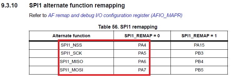
I guess the “simplest” “whole port write” would be to put all the datalines on GPIOA on a maple mini, but that would then take the SPI1 pins as well, which i was hoping to use for the touch screen, or can one use SPI2 with UTOUCH for example?
I guess i got a bit bitten when seeing just what kind of performance increase i got from digitalWrite to gpio_write_bit.
If the 16 data lines would be on different ports then it comes to the whole “masking” thing that i’m having problems understanding at the moment.
I’ll try 8 bit as well, and if it works i can post it here if some other newbie that doens’t have an spi tft to try?
If you need good display performance, you should invest in a board that has enough free pins that you can dedicate a whole port to the display.
(Its still only going to cost you less than $15 )
See this post my @madias about the boards he uses.
http://www.stm32duino.com/viewtopic.php … =650#p6841
But if you are not doing a lot of screen updates, then the difference in overall performance of your system e.g. including controlling SSR’s etc, may be mininal — But it really depends on the rest of your code.
In terms of whether a 72Mhz STM32 board is capable of handling the control of the brewing as well as operating a touch display. I would suspect that this would not be a problem.
However you need to make sure you don’t write “blocking” code, i.e don’t use delay() or do anything which waits in a while() loop for user input e.g. touch screen.
Some of the touch screen libraries have interrupt driven touch detection, so you should use that were possible
Alternatively you may want to look at using one of the RTOS frameworks that have been ported; I know that @victorpv had good results using FreeRTOS
I thought someone said that they had ported it, but I can’t remember where they posted to.
(Sorry)
I believe that Madias has a port of this library.
These displays are as cheap as chips and have an SD card thrown in, and are parallel, so theoretically they are faster than SPI so it would be good to get it working. They appear to come in a couple of different variants, so I’ll need to take a guess which one I have ![]()
It’s not the fastest approach, since i wasn’t sure how to do the operations on a whole (or parts of a) port.
Same approach would work for 8bit as well i guess
I have a shield that seems to have problems with the green, non all values are displayed. I found two other guys on the Arduino forum that has the same identical issue here https://forum.arduino.cc/index.php?topic=343637 and here https://forum.arduino.cc/index.php?topic=338835.0.
We all have issue on green channel. Do you have the same issue?
Anyone has a similar display and has it working with a maple mini?
Thanks!
Andreas
https://github.com/iwalpola/Adafruit_ILI9341_8bit_STM
Demo:
https://www.youtube.com/watch?v=MAkMaZyZMWM
all changes to original files were tracked with git, so that someone can learn by reading the commits.
Also, pinMode() has to be replaced by updating CRL and CRH, which I will do soon.
Did You also changed a library for touch screen for stm32? I’ve tried few examples but none of them works for me. Can You help me with that?
hardware/Arduino_STM32/STM32F1/variants/generic_stm32f103c/variant.h:18:14: error: 'uint8_t' does not name a type

static const uint8_t SCK  = BOARD_SPI1_SCK_PIN;
I haven’t had a play with this particular screen for a while, and I’m not getting much spare time.
Real life keeps throwing in large bunches of spanners..
int TouchScreen::readTouchY(void) {

pinMode(_xp, INPUT);

pinMode(_xm, INPUT);

digitalWrite(_xp, LOW);

digitalWrite(_xm, LOW);
pinMode(_yp, OUTPUT);
digitalWrite(_yp, HIGH);
pinMode(_ym, OUTPUT);
digitalWrite(_ym, LOW);
return (1023-analogRead(_xm));
}
In file included from /home/pilot/Pulpit/arduino-1.6.9/hardware/Arduino_STM32/STM32F1/variants/generic_stm32f103c/pins_arduino.h:6:0,

from /home/pilot/Pulpit/arduino-1.6.9/hardware/Arduino_STM32/STM32F1/libraries/Touch-Screen-Library_STM/TouchScreen_STM.cpp:8:

/home/pilot/Pulpit/arduino-1.6.9/hardware/Arduino_STM32/STM32F1/variants/generic_stm32f103c/variant.h:17:29: error: 'BOARD_SPI1_NSS_PIN' was not declared in this scope

static const uint8_t SS   = BOARD_SPI1_NSS_PIN;
^
/home/pilot/Pulpit/arduino-1.6.9/hardware/Arduino_STM32/STM32F1/variants/generic_stm32f103c/variant.h:18:29: error: 'BOARD_SPI2_NSS_PIN' was not declared in this scope
static const uint8_t SS1 = BOARD_SPI2_NSS_PIN;
^
/home/pilot/Pulpit/arduino-1.6.9/hardware/Arduino_STM32/STM32F1/variants/generic_stm32f103c/variant.h:19:29: error: 'BOARD_SPI1_MOSI_PIN' was not declared in this scope
static const uint8_t MOSI = BOARD_SPI1_MOSI_PIN;
^
/home/pilot/Pulpit/arduino-1.6.9/hardware/Arduino_STM32/STM32F1/variants/generic_stm32f103c/variant.h:20:29: error: 'BOARD_SPI1_MISO_PIN' was not declared in this scope
static const uint8_t MISO = BOARD_SPI1_MISO_PIN;
^
/home/pilot/Pulpit/arduino-1.6.9/hardware/Arduino_STM32/STM32F1/variants/generic_stm32f103c/variant.h:21:29: error: 'BOARD_SPI1_SCK_PIN' was not declared in this scope
static const uint8_t SCK = BOARD_SPI1_SCK_PIN;
The error you got is that those defines are not loaded from STM32F1/variants/maple/board/board.h where they are defined, probably because this file never loaded, probably because your sketch doesn’t include “Arduino.h” as the first header.
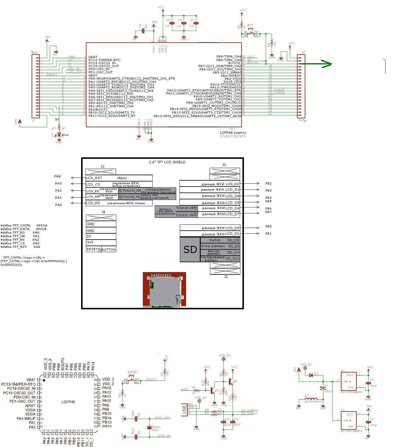
#define YP PB6  // LCD_RS

#define XM PB7  // LCD_CS

#define YM PA0   // LCD_D0

#define XP PA1   // LCD_D1
sketch:
// Touch screen library with X Y and Z (pressure) readings as well

// as oversampling to avoid 'bouncing'

// This demo code returns raw readings, public domain
//for STM32
#define YP PB3 // must be an analog pin, use "An" notation!
#define XM PB4 // must be an analog pin, use "An" notation!
#define YM PB5 // can be a digital pin
#define XP PB6 // can be a digital pin
//for arduino
//#define YP A2 // must be an analog pin, use "An" notation!
//#define XM A3 // must be an analog pin, use "An" notation!
//#define YM 8 // can be a digital pin
//#define XP 9 // can be a digital pin
#define pressureThreshhold 20
#define platform 1 //1 for arduino, 2 for STM32
void setup(void) {
Serial.begin(115200);
}
void loop(void) {
// For better pressure precision, we need to know the resistance
// between X+ and X- Use any multimeter to read it
// For the one we're using, its 300 ohms (rxplate) across the X plate
getPoint_new(XP, YP, XM, YM, 300);
}
void getPoint_new(byte xp, byte yp, byte xm, byte ym, int rxplate) {
int x, y, z;
int samples[2];
byte i, valid;
byte xp_port = digitalPinToPort(xp);
byte yp_port = digitalPinToPort(yp);
byte xm_port = digitalPinToPort(xm);
byte ym_port = digitalPinToPort(ym);
byte xp_pin = digitalPinToBitMask(xp);
byte yp_pin = digitalPinToBitMask(yp);
byte xm_pin = digitalPinToBitMask(xm);
byte ym_pin = digitalPinToBitMask(ym);
valid = 1;
pinMode(yp, INPUT);
pinMode(ym, INPUT);
*portOutputRegister(yp_port) &= ~yp_pin;
*portOutputRegister(ym_port) &= ~ym_pin;
pinMode(xp, OUTPUT);
pinMode(xm, OUTPUT);
*portOutputRegister(xp_port) |= xp_pin;
*portOutputRegister(xm_port) &= ~xm_pin;
delayMicroseconds(20); // Fast ARM chips need to allow voltages to settle
for (i=0; i<2; i++) {
samples[i] = analogRead(yp);
}
// Allow small amount of measurement noise, because capacitive
// coupling to a TFT display's signals can induce some noise.
if (samples[0] - samples[1] < -4 || samples[0] - samples[1] > 4) {
valid = 0;
} else {
samples[1] = (samples[0] + samples[1]) >> 1; // average 2 samples
}
x = (1023-samples[1]);
pinMode(xp, INPUT);
pinMode(xm, INPUT);
*portOutputRegister(xp_port) &= ~xp_pin;
pinMode(yp, OUTPUT);
*portOutputRegister(yp_port) |= yp_pin;
pinMode(ym, OUTPUT);
delayMicroseconds(20); // Fast ARM chips need to allow voltages to settle
for (i=0; i<2; i++) {
samples[i] = analogRead(xm);
}
// Allow small amount of measurement noise, because capacitive
// coupling to a TFT display's signals can induce some noise.
if (samples[0] - samples[1] < -4 || samples[0] - samples[1] > 4) {
valid = 0;
} else {
samples[1] = (samples[0] + samples[1]) >> 1; // average 2 samples
}
y = (1023-samples[1]);
// Set X+ to ground
pinMode(xp, OUTPUT);
*portOutputRegister(xp_port) &= ~xp_pin;
// Set Y- to VCC
*portOutputRegister(ym_port) |= ym_pin;
// Hi-Z X- and Y+
*portOutputRegister(yp_port) &= ~yp_pin;
pinMode(yp, INPUT);
int z1 = analogRead(xm);
int z2 = analogRead(yp);
if (rxplate != 0) {
// now read the x
float rtouch;
rtouch = z2;
rtouch /= z1;
rtouch -= 1;
rtouch *= x;
rtouch *= rxplate;
rtouch /= 1024;
z = rtouch;
} else {
z = (1023-(z2-z1));
}
if (! valid) {
z = 0;
}
if (z > pressureThreshhold && z < 1000){
Serial.print("X = "); Serial.print(x);
Serial.print("\tY = "); Serial.print(y);
Serial.print("\tPressure = "); Serial.println(z);
}
}
gpio_dev* xp_port = digitalPinToPort(xp);

gpio_dev* yp_port = digitalPinToPort(yp);

gpio_dev* xm_port = digitalPinToPort(xm);

gpio_dev* ym_port = digitalPinToPort(ym);
//for STM32

#define YP PB0  // RS must be an analog pin, use "An" notation!

#define XM PA0  // CS must be an analog pin, use "An" notation!

#define YM PB7   // D0 can be a digital pin

#define XP PA1   // D1 can be a digital pin
#define pressureThreshhold 20
#define NUMSAMPLES 6
void setup(void) {
Serial.begin(115200);
}
void loop(void) {
// For better pressure precision, we need to know the resistance
// between X+ and X- Use any multimeter to read it
// For the one we're using, its 300 ohms (rxplate) across the X plate
getPoint_new(XP, YP, XM, YM, 300);
}
void getPoint_new(byte xp, byte yp, byte xm, byte ym, int rxplate) {
int x, y, z;
int samples[NUMSAMPLES];
byte i, valid;
gpio_dev* xp_port = digitalPinToPort(xp);
gpio_dev* yp_port = digitalPinToPort(yp);
gpio_dev* xm_port = digitalPinToPort(xm);
gpio_dev* ym_port = digitalPinToPort(ym);
byte xp_pin = digitalPinToBitMask(xp);
byte yp_pin = digitalPinToBitMask(yp);
byte xm_pin = digitalPinToBitMask(xm);
byte ym_pin = digitalPinToBitMask(ym);
valid = 1;
pinMode(yp, INPUT);
pinMode(ym, INPUT);
*portOutputRegister(yp_port) &= ~yp_pin;
*portOutputRegister(ym_port) &= ~ym_pin;
pinMode(xp, OUTPUT);
pinMode(xm, OUTPUT);
*portOutputRegister(xp_port) |= xp_pin;
*portOutputRegister(xm_port) &= ~xm_pin;
for (i=0; i<NUMSAMPLES; i++) {
samples[i] = analogRead(yp);
}
insert_sort(samples, NUMSAMPLES);
x = (4096-samples[NUMSAMPLES/2]);
pinMode(xp, INPUT);
pinMode(xm, INPUT);
*portOutputRegister(xp_port) &= ~xp_pin;
pinMode(yp, OUTPUT);
*portOutputRegister(yp_port) |= yp_pin;
pinMode(ym, OUTPUT);
for (i=0; i<NUMSAMPLES; i++) {
samples[i] = analogRead(xm);
}
insert_sort(samples, NUMSAMPLES);
y = (4096-samples[NUMSAMPLES/2]);
// Set X+ to ground
pinMode(xp, OUTPUT);
*portOutputRegister(xp_port) &= ~xp_pin;
// Set Y- to VCC
*portOutputRegister(ym_port) |= ym_pin;
// Hi-Z X- and Y+
*portOutputRegister(yp_port) &= ~yp_pin;
pinMode(yp, INPUT);
int z1 = analogRead(xm);
int z2 = analogRead(yp);
if (rxplate != 0) {
// now read the x
float rtouch;
rtouch = z2;
rtouch /= z1;
rtouch -= 1;
rtouch *= x;
rtouch *= rxplate;
rtouch /= 1024;
z = rtouch;
} else {
z = (1023-(z2+z1));
}
if (! valid) {
z = 0;
}
if (z > pressureThreshhold && z < 1000){
Serial.print("X = "); Serial.print(x);
Serial.print("\tY = "); Serial.print(y);
Serial.print("\tPressure = "); Serial.println(z);
}
}
static void insert_sort(int array[], uint8_t size) {
uint8_t j;
int save;
for (int i = 1; i < size; i++) {
save = array[i];
for (j = i; j >= 1 && save < array[j - 1]; j--)
array[j] = array[j - 1];
array[j] = save;
}
}
BTW, there was a typo in the comments of Adafruit_ILI9341_8bit_STM.h :
//Pin stm32 |PA7|PA6|PA5|PA4|PA3|PA2|PC1|PA0|#define TFT_CNTRL GPIOB
#define TFT_DATA GPIOA
Port data |D7 |D6 |D5 |D4 |D3 |D2 |D1 |D0 |
Pin stm32 |PB7|PB6|PB5|PB4|PB3|PB2|PB1|PB0|
Control pins |RD |WR |RS |CS |RST|
Pin stm32 |PA4|PA5|PA6|PA7|PA8|
But there is small problem. There is no PB2 pin : http://www.stm32duino.com/download/file.php?id=17
#define TFT_CNTRL      GPIOA

#define TFT_DATA       GPIOB
The Maple mini leaves Boot1 floating.
This only becomes an issue if you want to flash via Serial, in which. case you need to make sure Boot1 is pulled low, otherwise flashing via serial is unreliable as the code can get flashed into RAM not ROM
Port data |D7 |D6 |D5 |D4 |D3 |D2 |D1 |D0 |

Pin stm32 |PB7|PB6|PB5|PB4|PB3|PB2|PB1|PB0|
Control pins |RD |WR |RS |CS |RST|
Pin stm32 |PA4|PA5|PA6|PA7|PA8|
I bought a similar board (2.4 inch touch LCD), and I am planning to make it run next days (tomorrow at soonest) with a blue pill.
My requirements:
– use USB serial for monitoring
– use SPI for SD card -> port pins PA4..7
– use touch screen -> port pins PA0..3
– use 8 data pins -> port pins PB8..15
– use control pins -> freely configurable on remaining port pins
I am going to use the @iwapola version, which seems pretty nicely speed optimized.
However, I see that the control pins are too restrictively coded, and I will then remap them in a more flexible configurable way.
I will then share my working version, which you could take 1 to 1 if this pin mapping would be OK for you.
According to this site, it seems that the pins XP and YM are shared with D6 and D7, YP and XM with LCD_WR and LCD_CD (marked as LCD_RS on my board), respectively.
//I need to change the pins below for it to work. NOt sure why

#define YP A1  // must be an analog pin, use "An" notation!

#define XM A2  // must be an analog pin, use "An" notation!

#define YM 7   // can be a digital pin

#define XP 6   // can be a digital pin
#define TS_MINX 150

#define TS_MINY 120

#define TS_MAXX 920

#define TS_MAXY 940
// For better pressure precision, we need to know the resistance

// between X+ and X- Use any multimeter to read it

// For the one we're using, its 300 ohms across the X plate

TouchScreen ts = TouchScreen(XP, YP, XM, YM, 300);
#define LCD_CS A3

#define LCD_CD A2

#define LCD_WR A1

#define LCD_RD A0

// optional

#define LCD_RESET A4
at first thanks for the great work all together
the library for the 8bit lcd is working just fine and its really fast!.
But now i want to use the touch screen and need analog control pins.
As you told before i swapped the ports and used b8 to b15 for the data.
#define TFT_CNTRL      GPIOA

#define TFT_DATA       GPIOB

#define TFT_RD         PA4

#define TFT_WR         PA5

#define TFT_RS         PA6

#define TFT_CS         PA7

#define TFT_RST        PA8
everything is working now, i just edited and saved the wrong file (same file wrong folder)
everything is working now, i just edited and saved the wrong file (same file wrong folder)
http://wiki.stm32duino.com/images/c/c1/ … ematic.pdf
So should still be OK
Edit, assuming the schematic we have for the BluePill is correct and they have not changed the design
I looked at my RedPill and it doesnt have a PB2 pin
So I looked at the schematic again, and PB2 is not broken out to the pins (which is the same as on the Maple mini) – probably as its Boot1 (even though it could be used)
So the OP needs to let us know what board they are using, or perhaps they are confusing PB2 with another pin
I can’t see it on my RedPill
I can’t see it on my RedPill
One pair has a bit larger resistance than the other pair because of the display geometry (4:3), I suppose.
In this way I figured out that on my display the touch pins are mapped as follows:
(XP-XM): LCD_WR – D0 = ~330 ohm
(YP-YM): LCD_CD(or _RS) – D1 = ~500 ohm
So, in my case, it is not D6 and D7 which are used, as posted earlier.
But I think it is different from display to display.
It seems like it is the same as in this datasheet http://wiki.stm32duino.com/images/c/c1/ … ematic.pdf
.
That board does not have a pin PB2
Which pin do you think is PB2.
(Image from your ebay link)
Edit: should I maybe unsolder Resistor on this pin ?
I doubt you can drive the display through 100k , you would need to replace the 100k witha much lower value resistor.
I make on this pins
Port data |D7 |D6 |D5 |D4 |D3 |D2 |D1 |D0 |

Pin stm32 |PB7|PB6|PB5|PB4|PB3|PB2|PB1|PB0|
Control pins |RD |WR |RS |CS |RST|
Pin stm32 |PA4|PA5|PA6|PA7|PA8|
or U can try this one : http://www.stm32duino.com/viewtopic.php … =30#p16026 for Your sketch
But if You are using library which was included into STM32 for arduino package You will not be able to run it. That one is not working. Try using function in the first link.
//#include "pins_arduino.h"Edit: should I maybe unsolder Resistor on this pin ?
//#include "pins_arduino.h"//#include "pins_arduino.h"what do you mean under “not working”? does it compile? do you get any printouts?
have you identified the pins for x and y plates (XP, YP,XM, YM) ?
what do you mean under “not working”? does it compile? do you get any printouts?
have you identified the pins for x and y plates (XP, YP,XM, YM) ?
you should enable the serial prints to see what is going on….
you should enable the serial prints to see what is going on….
you should enable the serial prints to see what is going on….
like this code :
uint16_t TouchScreen::pressure(void) {

// Set X+ to ground

pinMode(_xp, OUTPUT);

digitalWrite(_xp, LOW);
// Set Y- to VCC

pinMode(_ym, OUTPUT);

digitalWrite(_ym, HIGH);
// Hi-Z X- and Y+

digitalWrite(_xm, LOW);

pinMode(_xm, INPUT);

digitalWrite(_yp, LOW);

pinMode(_yp, INPUT);
int z1 = analogRead(_xm);

int z2 = analogRead(_yp);
if (_rxplate != 0) {

// now read the x

float rtouch;

rtouch = z2;

rtouch /= z1;

rtouch -= 1;

rtouch *= readTouchX();

rtouch *= _rxplate;

#if !defined (__STM32F1__)

rtouch /= 1024;

#else

rtouch /= 4095;

#endif
return rtouch;

} else {

#if !defined (__STM32F1__)

return (1023-(z2-z1));

#else

return (4095-(z2-z1));

#endif

}

}
EDIT: Problem with the screen arise when I’m adding touch settings to the screen preview code :/
In the link I provided earlier, if you scroll further to bottom of page, it is another code snippet where is explicitly stated:
#define MINPRESSURE 10

#define MAXPRESSURE 1000
void loop()

{

digitalWrite(13, HIGH);

TSPoint p = ts.getPoint();

digitalWrite(13, LOW);
// ***** if sharing pins, you'll need to fix the directions of the touchscreen pins *****

//pinMode(XP, OUTPUT);

pinMode(XM, OUTPUT);

pinMode(YP, OUTPUT);

//pinMode(YM, OUTPUT);
// we have some minimum pressure we consider 'valid'

// pressure of 0 means no pressing!
if (p.z > MINPRESSURE && p.z < MAXPRESSURE) {

...
EDIT: no I didn’t measure it. to be honest I didn’t know how so I was trying what is the best configuration :/
// overlaps:

#define YP LCD_CD //(RS?)	// 330 Ohm

#define XM LCD_D1 // 500 Ohm

#define YM LCD_D0 // 330 Ohm

#define XP LCD_CS // 500 Ohm
For this, the following pins (additionally to the plate pins) should be connected correspondingly:
Vcc(3.3V),
GND,
and – important!
LCD_RD – >tied to Vcc. This line switches correctly the direction of one of the bus transceivers (HC245) on the board, on which LCD_D0 and D1 are connected. Only if this pin is high, the pins LCD_D0 and D1 (YM,XM) can be used as analog input.
EDIT
Hm, I think I just had luck, there is no rule to which pin are the plate pins connected, I saw several different variants on the net.
But all of them have U3 switching the LCD_D0..D7 pins upon LCD_RD signal.
The only reliable plate detection method is still the resistance measurement, although most common is to use LCD_D6, D7. My board uses LCD_D0,D1.
The other side of the plates is usually connected to LCD_WR+CD, my board use LCD_CS+RS(CD).
everything is working now, i just edited and saved the wrong file (same file wrong folder)
Here is working code for both TFT Screen and touch – read comments for settings and connections.
// @konczakp

//

// TFT settings

// in Adafruit_ILI9341_8bit_STM.h

//

//  #define TFT_CNTRL      GPIOA

//  #define TFT_DATA       GPIOB

//  #define TFT_RD         PA4

//  #define TFT_WR         PA5

//  #define TFT_RS         PA6

//  #define TFT_CS         PA7

//  #define TFT_RST        PA8

//

// Connection

// Port data |D7 |D6 |D5 |D4 |D3 |D2 |D1 |D0 |

// Pin stm32 |PB7|PB6|PB5|PB4|PB3|PB2|PB1|PB0|
// Control pins |RD |WR |RS |CS |RST|
// Pin stm32 |PA4|PA5|PA6|PA7|PA8|
#include <Adafruit_GFX.h>
#include <gfxfont.h>
#include "Adafruit_ILI9341_8bit_STM.h"
#define YP PA6 // LCD_RS
#define XM PA7 // LCD_CS
#define YM PB0 // LCD_D0
#define XP PB1 // LCD_D1
#define pressureThreshhold 20
#define NUMSAMPLES 12
Adafruit_ILI9341_8bit_STM tft = Adafruit_ILI9341_8bit_STM();
void testLines(uint16_t color)
{
int x1, y1, x2, y2,
w = tft.width(),
h = tft.height();
tft.fillScreen(ILI9341_BLACK);
x1 = 0;
y1 = h - 1;
y2 = 0;
for(x2=0; x2<w; x2+=6) tft.drawLine(x1, y1, x2, y2, color);
x2 = w - 1;
for(y2=0; y2<h; y2+=6) tft.drawLine(x1, y1, x2, y2, color);
}
void setup() {
Serial.begin (115200);
tft.begin();
tft.setRotation(1);
testLines(ILI9341_CYAN);
}
void loop()
{
getPoint_new(XP, YP, XM, YM, 300);
pinMode(XM, OUTPUT);
pinMode(YP, OUTPUT);
}
void getPoint_new(byte xp, byte yp, byte xm, byte ym, int rxplate) {
int x, y, z;
int samples[NUMSAMPLES];
byte i, valid;
gpio_dev* xp_port = digitalPinToPort(xp);
gpio_dev* yp_port = digitalPinToPort(yp);
gpio_dev* xm_port = digitalPinToPort(xm);
gpio_dev* ym_port = digitalPinToPort(ym);
byte xp_pin = digitalPinToBitMask(xp);
byte yp_pin = digitalPinToBitMask(yp);
byte xm_pin = digitalPinToBitMask(xm);
byte ym_pin = digitalPinToBitMask(ym);
valid = 1;
pinMode(yp, INPUT);
pinMode(ym, INPUT);
*portOutputRegister(yp_port) &= ~yp_pin;
*portOutputRegister(ym_port) &= ~ym_pin;
pinMode(xp, OUTPUT);
pinMode(xm, OUTPUT);
*portOutputRegister(xp_port) |= xp_pin;
*portOutputRegister(xm_port) &= ~xm_pin;
delayMicroseconds(20); // Fast ARM chips need to allow voltages to settle
for (i=0; i<NUMSAMPLES; i++) {
samples[i] = analogRead(yp);
}
insert_sort(samples, NUMSAMPLES);
x = (4096-samples[NUMSAMPLES/2]);
pinMode(xp, INPUT);
pinMode(xm, INPUT);
*portOutputRegister(xp_port) &= ~xp_pin;
pinMode(yp, OUTPUT);
*portOutputRegister(yp_port) |= yp_pin;
pinMode(ym, OUTPUT);
delayMicroseconds(20); // Fast ARM chips need to allow voltages to settle
for (i=0; i<NUMSAMPLES; i++) {
samples[i] = analogRead(xm);
}
insert_sort(samples, NUMSAMPLES);
y = (4096-samples[NUMSAMPLES/2]);
// Set X+ to ground
pinMode(xp, OUTPUT);
*portOutputRegister(xp_port) &= ~xp_pin;
// Set Y- to VCC
*portOutputRegister(ym_port) |= ym_pin;
// Hi-Z X- and Y+
*portOutputRegister(yp_port) &= ~yp_pin;
pinMode(yp, INPUT);
int z1 = analogRead(xm);
int z2 = analogRead(yp);
if (rxplate != 0) {
// now read the x
float rtouch;
rtouch = z2;
rtouch /= z1;
rtouch -= 1;
rtouch *= x;
rtouch *= rxplate;
rtouch /= 4096;
z = rtouch;
} else {
z = (1023-(z2-z1));
}
if (! valid) {
z = 0;
}
if (z > pressureThreshhold && z < 100){
Serial.print("X = "); Serial.print(x);
Serial.print("\tY = "); Serial.print(y);
Serial.print("\tPressure = "); Serial.println(z);
}
}
static void insert_sort(int array[], byte size) {
byte j;
int save;
for (int i = 1; i < size; i++) {
save = array[i];
for (j = i; j >= 1 && save < array[j - 1]; j--)
array[j] = array[j - 1];
array[j] = save;
}
}
Congratulations, it looks like you have the same pin mapping as my board.
But you don’t use the SD card, right? Otherwise you would need PA4..PA7 for SPI1.
About this pin mapping – I think it is the same for every shield from arduino. If some one bought tft 2,4 shield for arduino then It should work. I don’t know about larger screens but it is easy to check. Instead of measuring pin impedance You can compare to this shield http://supertronik.pl/img/wyswietlacz_mega2560_3.jpg and change as it is on the other shield. Everything I did was based on Arduino code.
Btw, any one know how to assign rect aera for the touch screen to check if the btn on screen was clicked?
EDIT: an another thing … is there an option to turn off the screen and switch it on if the screen was touched ?
YP is LCD_RS

XM is LCD_CS

YM is LCD_D0

XP is LCD_D1
i changed to pin A0-A3 and A8 for the controls, all you need to change is in line 20 of Adafruit_ILI9341_8bit_STM.cpp
TFT_CNTRL->regs->CRL = (TFT_CNTRL->regs->CRL & 0x0000FFFF) | 0x33330000;
No, it is not normal. I also got this behavior before I figured out the LCD_RD pin dependency.
here is a simple sketch for using display and touch, you have to have working libraries somehow and change the pins if yours are different, the rest should be working
(drawing with red pen)
// Touch screen library with X Y and Z (pressure) readings as well

// as oversampling to avoid 'bouncing'

// This demo code returns raw readings, public domain
#include <Adafruit_GFX.h>

#include <gfxfont.h>

#include <TouchScreen_STM.h>

#include "Adafruit_ILI9341_8bit_STM.h"

// These are the pins for the shield!

#define YP PA2  // must be an analog pin

#define XM PA3  // must be an analog pin

#define YM PB8   // can be a digital pin

#define XP PB9   // can be a digital pin

#define RD PA0
#define XMIN 500

#define XMINBLACK 320

#define XMAX 3740

#define YMIN 420

#define YMAX 3640
#define MINPRESSURE 20

#define MAXPRESSURE 1000
// For better pressure precision, we need to know the resistance

// between X+ and X- Use any multimeter to read it

// For the one we're using, its 300 ohms across the X plate

TouchScreen ts = TouchScreen(XP, YP, XM, YM, 300);

Adafruit_ILI9341_8bit_STM tft = Adafruit_ILI9341_8bit_STM();

void setup(void) {

//Serial.begin(9600);

delay(5);

tft.begin();
//digitalWrite(RD, LOW);

tft.fillScreen(ILI9341_BLACK);

tft.setRotation(1);

delay(1000);

}
void loop(void) {
pinMode(RD,OUTPUT);

digitalWrite(RD, HIGH);

TSPoint p = ts.getPoint();

//set controlpins to output again

TFT_CNTRL->regs->CRL = (TFT_CNTRL->regs->CRL & 0xFFFF0000) | 0x00003333;
// we have some minimum pressure we consider 'valid'

// pressure of 0 means no pressing!

if (p.z > MINPRESSURE && p.z < MAXPRESSURE) {

int16_t x=calculateX(p.x);

int16_t y=calculateY(p.y);

//Serial.print("X = "); Serial.print(x);

//Serial.print("\tY = "); Serial.print(y);

//Serial.print("\tPressure = "); Serial.println(p.z);

tft.fillCircle(x, y, 3, ILI9341_RED);

}

}

uint16_t calculateX(uint16_t x)

{

return 320-(320*(x-XMIN))/(XMAX-XMIN);

}

uint16_t calculateY(uint16_t y)

{

return (240*(y-YMIN))/(YMAX-YMIN);

}
TFT_CNTRL->regs->CRL = (TFT_CNTRL->regs->CRL & 0xFFFF0000) | 0x00003333;
TFT_CNTRL->regs->CRL = (TFT_CNTRL->regs->CRL & 0xFFFF0000) | 0x00003333;
Because both SPI are free does anyone have a working sd card sketch ?
take the QuickStart one it works
@stevestrong – in one of the topics about using sd card You have mentioned that You are using SPI.setModule(2) and it is working. Can You share Your code please?
i have another problem with my touchscreen, i dont know if it is broken or any bit set wrong ![]() even if RD is set high and the code is the same as before the input doesnt get detected right, i have also measured double resistance on the x-achses with the multimeter(two time the resistance on the x-achses one day before)…does anyone see the same behavior or have an idea?
even if RD is set high and the code is the same as before the input doesnt get detected right, i have also measured double resistance on the x-achses with the multimeter(two time the resistance on the x-achses one day before)…does anyone see the same behavior or have an idea?
About this SD card. I was trying to get it working on SPI1 too but no success. This is my pin connection:
SD pins     |SCK |D0  |D1  |SS  |

Pin stm32 |PA5 |PA6 |PA7 |PA4|
- spi1.png (27.05 KiB) Viewed 567 times

I think You misunderstood me. This is my sd adapter. There is voltage regulator so I don’t care about voltage. screen need to be connected with 3.3 and 5v. sd card adaptor is on the screen board.
Of course, you are using the on-board SD adapter. So it should work with the 3.3V.
Be sure that the 3.3V supply can give up to 1A.
I will test it in the evening at home and let you know the results.
The 3.3V is also fed from the 5V power regulator.
U2 = U3 = HC245
maybe because it is long time ago since I checked out last time.
sorry, but it seems that I will not be able to compile it today
IIRC there were ILI9320, 25, 35, 41 and 86, all with resistive touch w/o controller and micro SD slot.
The adafruit libs didn’t work for me, same for all other libs recommended by all those lovely internet forums
Just when I finished a lib that could handle one out my fundus I found one that did all and much faster than my own crap.
What did I learn?
Every display has another routing for its touch, even when format and controller match.
So there is only one way to go: try and try and try…
SD slot is working at all but one, there was a poor ratching.
It can be accessed via SPI, please have a look at the adfruit tftlib examples.
I reworked a little bit the touch lib, by introducing some features like:
– easily detecting touch and getting coordinates in one function call
– mapping of the returned coordinates to the display resolution (default: 320×240)
– semi-automatic (user-assisted) easy calibration process (requires touching two opposite corners of the display).
If interested how to use it, please check the included INO example.
Any (constructive) comment is welcome.
Have fun!
The clou: the board must be powered with 5V!
In this case remove the 3.3V wire from the pill.
It did not work with the 3.3V from the blue pill, probably the 3.3V regulator of the pill is not strong enough for the SD adapter too.
*** Touch demo with easy calibration + SD card info ***

Calibrating the touch surface

> please press one corner...ok.

> and now press the diagonally opposite corner...ok.

Calibration done!
SdFat version: 20150321
Assuming the SD is the only SPI device.
Edit DISABLE_CHIP_SELECT to disable another device.
Assuming the SD chip select pin is: 4
Edit SD_CHIP_SELECT to change the SD chip select pin.
touch the screen to start
X = 319, Y = 81, Z = 1296
init time: 9 ms
Card type: SDHC
Manufacturer ID: 0X3
OEM ID: SD
Product: SL16G
Version: 8.0
Serial number: 0X72F2CA43
Manufacturing date: 8/2015
cardSize: 15931.54 MB (MB = 1,000,000 bytes)
flashEraseSize: 128 blocks
eraseSingleBlock: true
OCR: 0XC0FF8000
SD Partition Table
part,boot,type,start,length
1,0X0,0XC,8192,31093648
2,0X0,0X0,0,0
3,0X0,0X0,0,0
4,0X0,0X0,0,0
Volume is FAT32
blocksPerCluster: 64
clusterCount: 485710
freeClusters: 485700
freeSpace: 15915.42 MB (MB = 1,000,000 bytes)
fatStartBlock: 8794
fatCount: 2
blocksPerFat: 3795
rootDirStart: 2
dataStartBlock: 16384
touch the screen to start
The SD card connection, additionally to 5V extern and GND from pill, is straightforward.
Be careful: don’t mix port names PAx with Ax !
STM32   TFT

PA4     SD_SS

PA5     SD_SCK

PA6     SD_DO (=MISO)

PA7     SD_DI (=MOSI)
One pair has a bit larger resistance than the other pair because of the display geometry (4:3), I suppose.
In this way I figured out that on my display the touch pins are mapped as follows:
(XP-XM): LCD_WR – D0 = ~330 ohm
(YP-YM): LCD_CD(or _RS) – D1 = ~500 ohm
So, in my case, it is not D6 and D7 which are used, as posted earlier.
But I think it is different from display to display.
Be sure that this pin is set to “high” (“1”) to use the touch pins.
Be sure that this pin is set to “high” (“1”) to use the touch pins.
If you use the 3.3V from the blue pill (STM32), it may not be enough to drive the backlight, SD card and the LCD all together.
I would suggest you to use 5V.
I’ve been reading through this thread, and am getting a little lost..
I have a TFT (as mentioned earlier) labelled “TFT_320QVT_9341”.
It has DB0 – DB-15.
Which lib should I be using, and is it still possible to change the pin config on the STM32F4(Discovery)?
Is there any reference as to how other people have routed in and configured?
(There seem to be a lot of sketches, but I am unsure which one I should be following).
https://www.element14.com/community/gro … 2d-tft-lcd
Will this work?
@stevestrong I have tried Your sd card code and unfortunately it is not working ![]() I have connected as You mentioned but still nothing. I have bought even another board to do tests (maple mini) but nothing changed
I have connected as You mentioned but still nothing. I have bought even another board to do tests (maple mini) but nothing changed ![]() I was trying via 5v and after that with 3.3v and at last both. I have connected only pins for the sd card, everything else is not connected. I don’t really know what I’m doing wrong, I think I’m missing some small part which I don’t see or I don’t know where is the problem. I know that the card is working because I did a test with arduino and a simple code cardinfo from adruino IDE. On ardiono everything works fine but not on the maple mini / blue pill.
I was trying via 5v and after that with 3.3v and at last both. I have connected only pins for the sd card, everything else is not connected. I don’t really know what I’m doing wrong, I think I’m missing some small part which I don’t see or I don’t know where is the problem. I know that the card is working because I did a test with arduino and a simple code cardinfo from adruino IDE. On ardiono everything works fine but not on the maple mini / blue pill.
Because I don’t know how to find a problem below is my code and connection schematics :
connection
FTDI 	     maple mini	      TFT_SD

(USB-to-RS)

| -----Rx------|------Tx-------|

| -----Tx------|------Rx-------|

| ----GND------|------GND------|-----GND------|

| ----+3v------|------VCC------|

|------PA4------|----SD_SS-----|

|------PA5------|----SD_SCK----|

|------PA6------|----SD_MISO---|

|------PA7------|----SD_MOSI---|

|------+5v-----|---------------> +5v from USB (GND already connected via PC and FTDI)
For me this code is working :
/*

SD card read/write
created Nov 2010
by David A. Mellis
modified 9 Apr 2012
by Tom Igoe
This example code is in the public domain.
*/
#include <SPI.h>
#include <SD.h>
File myFile;
void setup() {
// Open serial communications and wait for port to open:
Serial.begin(115200);
delay(4000);
Serial.print("Initializing SD card...");
if (!SD.begin(PA4)) {
Serial.println("initialization failed!");
return;
}
Serial.println("initialization done.");
// open the file. note that only one file can be open at a time,
// so you have to close this one before opening another.
myFile = SD.open("test.txt", FILE_WRITE);
// if the file opened okay, write to it:
if (myFile) {
Serial.print("Writing to test.txt...");
myFile.println("testing 1, 2, 3.");
// close the file:
myFile.close();
Serial.println("done.");
} else {
// if the file didn't open, print an error:
Serial.println("error opening test.txt");
}
// re-open the file for reading:
myFile = SD.open("test.txt");
if (myFile) {
Serial.println("test.txt:");
// read from the file until there's nothing else in it:
while (myFile.available()) {
Serial.write(myFile.read());
}
// close the file:
myFile.close();
} else {
// if the file didn't open, print an error:
Serial.println("error opening test.txt");
}
}
void loop() {
// nothing happens after setup
}
https://github.com/greiman/SdFat
Try the examples, it should work.
PS: the above code is old.
So try the version from my repo.
Victor has not been on the forum for ages, I think we have to assume he is no longer actively maintaining any of his repo’s etc
Or did Victors changes not get implemented by the original author of the lib ?
stm32f103c8t6 does not have the PC1, this is a mistake?
maybe PA1 ?
functions called write8(), setWriteDataBus()//#define TFT_DATA GPIOA
void Adafruit_ILI9341_8bit_STM::setWriteDataBus(void)

{

//set the pins to output mode

//not required to mask and assign, because all pins of bus are set together

TFT_DATA->regs->CRL = 0x33333333;

//each pin is configured by four bits, and 0b0011 or 0x3 means output mode (same as pinmode())

}
Yes Spfd5408 2.4” TFT screen is working with maple mini and blue pill very well. You have to read this topic carefully because everything is here also with a way of connecting tft to stm32 and also what to change and how in the libraries. Few posts earlier I posted everything You need to get this working (also with working sketch example) For example here is how to modify library http://www.stm32duino.com/viewtopic.php … 110#p16273 and below is an example from cologne86. This should help You to get this working.
I change in Adafruit_ILI9341_8bit_STM.h
#define TFT_CNTRL GPIOA
#define TFT_DATA GPIOB
#define TFT_RD PA0
#define TFT_WR PA1
#define TFT_RS PA2
#define TFT_CS PA3
#define TFT_RST PA8
and
TFT_CNTRL->regs->CRL = (TFT_CNTRL->regs->CRL & 0xFFFF0000) | 0x00003333;
in Adafruit_ILI9341_8bit_STM.cpp
======================================================
connect
- 111.jpg (157.91 KiB) Viewed 720 times
here is what i have right now, works for my ili9341 and almost works for the ili9328/ili9325 (slower and doesnt work in landscape reverse)
with pb8-pb15 as d0-d7
i dont exactly remember what i have modified but it should still run with good performance for the ili9341
i have also added a pushcolors function for displaying sdcard stuff faster
.h
/*

See rights and use declaration in License.h

This library has been modified for the Maple Mini

*/
#ifndef _ADAFRUIT_ILI9341H_
#define _ADAFRUIT_ILI9341H_
#include "Arduino.h"
#include "Print.h"
#include <Adafruit_GFX.h>
#include <avr/pgmspace.h>
#define TFTLCD_DELAY 0xFF
#define ILI9341_TFTWIDTH 240
#define ILI9341_TFTHEIGHT 320
#define ILI9341_NOP 0x00
#define ILI9341_SWRESET 0x01
#define ILI9341_RDDIDIF 0x04
#define ILI9341_RDDID 0xD3
#define ILI9341_RDDST 0x09
#define ILI9341_SLPIN 0x10
#define ILI9341_SLPOUT 0x11
#define ILI9341_PTLON 0x12
#define ILI9341_NORON 0x13
#define ILI9341_RDMODE 0x0A
#define ILI9341_RDMADCTL 0x0B
#define ILI9341_RDPIXFMT 0x0C
#define ILI9341_RDIMGFMT 0x0D
#define ILI9341_RDDSM 0x0E
#define ILI9341_RDSELFDIAG 0x0F
#define ILI9341_INVOFF 0x20
#define ILI9341_INVON 0x21
#define ILI9341_GAMMASET 0x26
#define ILI9341_DISPOFF 0x28
#define ILI9341_DISPON 0x29
#define ILI9341_CASET 0x2A
#define ILI9341_PASET 0x2B
#define ILI9341_RAMWR 0x2C
#define ILI9341_RGBSET 0x2D
#define ILI9341_RAMRD 0x2E
#define ILI9341_PTLAR 0x30
#define ILI9341_VSCRDEF 0x33
#define ILI9341_TEOFF 0x34
#define ILI9341_TEON 0x35
#define ILI9341_MADCTL 0x36
#define ILI9341_VSCRSADD 0x37
#define ILI9341_IDMOFF 0x38
#define ILI9341_IDMON 0x39
#define ILI9341_PIXFMT 0x3A
#define ILI9341_FRMCTR1 0xB1
#define ILI9341_FRMCTR2 0xB2
#define ILI9341_FRMCTR3 0xB3
#define ILI9341_INVCTR 0xB4
#define ILI9341_PRCTR 0xB5
#define ILI9341_DFUNCTR 0xB6
#define ILI9341_ETMOD 0xB7
#define ILI9341_PWCTR1 0xC0
#define ILI9341_PWCTR2 0xC1
#define ILI9341_PWCTR3 0xC2
#define ILI9341_PWCTR4 0xC3
#define ILI9341_PWCTR5 0xC4
#define ILI9341_VMCTR1 0xC5
#define ILI9341_VMCTR2 0xC7
#define ILI9341_PWCTRLA 0xCB
#define ILI9341_PWCTRLB 0xCF
#define ILI9341_RDID1 0xDA
#define ILI9341_RDID2 0xDB
#define ILI9341_RDID3 0xDC
#define ILI9341_RDID4 0xD3
#define ILI9341_GMCTRP1 0xE0
#define ILI9341_GMCTRN1 0xE1
#define ILI9341_DGAMCTRL1 0xE2
#define ILI9341_DGAMCTRL2 0xE3
#define ILI9341_TCTRLA 0xE8
#define ILI9341_TCTRLB 0xEA
#define ILI9341_PWRSEQ 0xED
#define ILI9341_EN3GAM 0xF2
#define ILI9341_IFCTL 0xF6
#define ILI9341_PUMP 0xF7
#define ILI9341_MADCTL_MV BIT(5)
#define ILI9341_MADCTL_MX BIT(6)
#define ILI9341_MADCTL_MY BIT(7)
#define ILI932X_START_OSC 0x00
#define ILI932X_DRIV_OUT_CTRL 0x01
#define ILI932X_DRIV_WAV_CTRL 0x02
#define ILI932X_ENTRY_MOD 0x03
#define ILI932X_RESIZE_CTRL 0x04
#define ILI932X_DISP_CTRL1 0x07
#define ILI932X_DISP_CTRL2 0x08
#define ILI932X_DISP_CTRL3 0x09
#define ILI932X_DISP_CTRL4 0x0A
#define ILI932X_RGB_DISP_IF_CTRL1 0x0C
#define ILI932X_FRM_MARKER_POS 0x0D
#define ILI932X_RGB_DISP_IF_CTRL2 0x0F
#define ILI932X_POW_CTRL1 0x10
#define ILI932X_POW_CTRL2 0x11
#define ILI932X_POW_CTRL3 0x12
#define ILI932X_POW_CTRL4 0x13
#define ILI932X_GRAM_HOR_AD 0x20
#define ILI932X_GRAM_VER_AD 0x21
#define ILI932X_RW_GRAM 0x22
#define ILI932X_POW_CTRL7 0x29
#define ILI932X_FRM_RATE_COL_CTRL 0x2B
#define ILI932X_GAMMA_CTRL1 0x30
#define ILI932X_GAMMA_CTRL2 0x31
#define ILI932X_GAMMA_CTRL3 0x32
#define ILI932X_GAMMA_CTRL4 0x35
#define ILI932X_GAMMA_CTRL5 0x36
#define ILI932X_GAMMA_CTRL6 0x37
#define ILI932X_GAMMA_CTRL7 0x38
#define ILI932X_GAMMA_CTRL8 0x39
#define ILI932X_GAMMA_CTRL9 0x3C
#define ILI932X_GAMMA_CTRL10 0x3D
#define ILI932X_HOR_START_AD 0x50
#define ILI932X_HOR_END_AD 0x51
#define ILI932X_VER_START_AD 0x52
#define ILI932X_VER_END_AD 0x53
#define ILI932X_GATE_SCAN_CTRL1 0x60
#define ILI932X_GATE_SCAN_CTRL2 0x61
#define ILI932X_GATE_SCAN_CTRL3 0x62
#define ILI932X_PART_IMG1_DISP_POS 0x80
#define ILI932X_PART_IMG1_START_AD 0x81
#define ILI932X_PART_IMG1_END_AD 0x82
#define ILI932X_PART_IMG2_DISP_POS 0x83
#define ILI932X_PART_IMG2_START_AD 0x84
#define ILI932X_PART_IMG2_END_AD 0x85
#define ILI932X_PANEL_IF_CTRL1 0x90
#define ILI932X_PANEL_IF_CTRL2 0x92
#define ILI932X_PANEL_IF_CTRL3 0x93
#define ILI932X_PANEL_IF_CTRL4 0x95
#define ILI932X_PANEL_IF_CTRL5 0x97
#define ILI932X_PANEL_IF_CTRL6 0x98
/*
#define ILI9341_PWCTR6 0xFC
*/
// Color definitions
#define ILI9341_BLACK 0x0000 /* 0, 0, 0 */
#define ILI9341_NAVY 0x000F /* 0, 0, 128 */
#define ILI9341_DARKGREEN 0x03E0 /* 0, 128, 0 */
#define ILI9341_DARKCYAN 0x03EF /* 0, 128, 128 */
#define ILI9341_MAROON 0x7800 /* 128, 0, 0 */
#define ILI9341_PURPLE 0x780F /* 128, 0, 128 */
#define ILI9341_OLIVE 0x7BE0 /* 128, 128, 0 */
#define ILI9341_LIGHTGREY 0xC618 /* 192, 192, 192 */
#define ILI9341_DARKGREY 0x7BEF /* 128, 128, 128 */
#define ILI9341_BLUE 0x001F /* 0, 0, 255 */
#define ILI9341_GREEN 0x07E0 /* 0, 255, 0 */
#define ILI9341_CYAN 0x07FF /* 0, 255, 255 */
#define ILI9341_RED 0xF800 /* 255, 0, 0 */
#define ILI9341_MAGENTA 0xF81F /* 255, 0, 255 */
#define ILI9341_YELLOW 0xFFE0 /* 255, 255, 0 */
#define ILI9341_WHITE 0xFFFF /* 255, 255, 255 */
#define ILI9341_ORANGE 0xFD20 /* 255, 165, 0 */
#define ILI9341_GREENYELLOW 0xAFE5 /* 173, 255, 47 */
#define ILI9341_PINK 0xF81F
/*
Define pins and Output Data Registers
*/
//Port data |D7 |D6 |D5 |D4 |D3 |D2 |D1 |D0 |
//Pin stm32 |PA7|PA6|PA5|PA4|PA3|PA2|PC1|PA0|
//Control pins |RD |WR |RS |CS |RST|
//Pin stm32 |PB4|PB5|PB6|PB7|PB8|
#define TFT_CNTRL GPIOA
#define TFT_DATA GPIOB
#define TFT_RD PA0
#define TFT_WR PA1
#define TFT_RS PA2
#define TFT_CS PA3
#define TFT_RST PA8
#define TFT_RD_MASK digitalPinToBitMask(TFT_RD)
#define TFT_WR_MASK digitalPinToBitMask(TFT_WR)
#define TFT_RS_MASK digitalPinToBitMask(TFT_RS)
#define TFT_CS_MASK digitalPinToBitMask(TFT_CS)
#define RD_ACTIVE TFT_CNTRL->regs->BRR = TFT_RD_MASK
#define RD_IDLE TFT_CNTRL->regs->BSRR = TFT_RD_MASK
#define WR_ACTIVE TFT_CNTRL->regs->BRR = TFT_WR_MASK
#define WR_IDLE TFT_CNTRL->regs->BSRR = TFT_WR_MASK
#define CD_COMMAND TFT_CNTRL->regs->BRR = TFT_RS_MASK
#define CD_DATA TFT_CNTRL->regs->BSRR = TFT_RS_MASK
#define CS_ACTIVE TFT_CNTRL->regs->BRR = TFT_CS_MASK
#define CS_IDLE TFT_CNTRL->regs->BSRR = TFT_CS_MASK
#ifndef RD_STROBE
#define RD_STROBE {RD_ACTIVE; RD_IDLE;}
#endif
#define WR_STROBE { WR_ACTIVE; WR_IDLE; }
#define swap(a, b) { int16_t t = a; a = b; b = t; }
//Set pins to the 8 bit number
#define write8special(c) { TFT_DATA->regs->BSRR = ((~c)<<24) | ((c)<<8); WR_STROBE; }
class Adafruit_ILI9341_8bit_STM : public Adafruit_GFX {
public:
Adafruit_ILI9341_8bit_STM(void);
void begin(void),
begin(uint16_t id),
setAddrWindow(uint16_t x0, uint16_t y0, uint16_t x1, uint16_t y1),
pushColors(uint16_t *data, uint8_t len, boolean first),
pushColors(uint8_t *data, uint8_t len, boolean first),
pushColor(uint16_t color),
fillScreen(uint16_t color),
#if defined (__STM32F1__)
drawLine(int16_t x0, int16_t y0,int16_t x1, int16_t y1, uint16_t color),
#endif
drawPixel(int16_t x, int16_t y, uint16_t color),
drawFastVLine(int16_t x, int16_t y, int16_t h, uint16_t color),
drawFastHLine(int16_t x, int16_t y, int16_t w, uint16_t color),
fillRect(int16_t x, int16_t y, int16_t w, int16_t h,
uint16_t color),
setRotation(uint8_t r),
write8(uint8_t),
writedata(uint8_t d),
writecommand(uint8_t c),
invertDisplay(boolean i);
uint16_t color565(uint8_t r, uint8_t g, uint8_t b);
/* These are not for current use, 8-bit protocol only! */
//uint8_t readdata(void),
uint8_t readcommand8(uint8_t reg);
uint32_t readID(void);
uint8_t driver;
private:
uint8_t tabcolor;
uint8_t read8(void);
void setReadDataBus(void),
setWriteDataBus(void),
commandList(uint8_t *addr),
flood(uint16_t color, uint32_t len),
writeRegister16(uint16_t a,uint16_t d) ;
#if defined (__STM32F1__)
uint16_t lineBuffer[ILI9341_TFTHEIGHT]; // DMA buffer. 16bit color data per pixel
#endif
};
#endif //endif of the header file
In my opinion You have a hardware problem. Have You got another screen to try? One of my screens was similar to Yours. Try to connect as it should be and gently squeeze with your fingers screen to the board in different areas while reseting the stm32 board. Check if something will happen. In my situation when I have squeezed on the left bottom corner it was working. There was some soldering problem. For me this doesn’t look as a library problem. When I had a problem with library it was only blinking or white screen on nothing else. Removing one data pin means that You are not transfering all info to the tft. Of course I might be wrong in this case.
@cologne86
inverted picture on the screen means that there is different chip and there is a need for different initialization for this screen in the library or different library.
By the way:
Anyone has got library for the eagle software ? I need it to prepare a board
I code program on atmel(arduino), but flash program memory is out.
I buy logic analyzer tomorrow and compare signals.
sorry my english bad
================================================================
in atmel(arduino) inicialization
else if (id == 0x9341) {
uint16_t a, d;
driver = ID_9341;
CS_ACTIVE;
writeRegister8(ILI9341_SOFTRESET, 0); //softreset == 0x01
delay(50);
writeRegister8(ILI9341_DISPLAYOFF, 0); //0x28
writeRegister8(ILI9341_POWERCONTROL1, 0x23);// команда 0xC0 а потом данные 0x23
writeRegister8(ILI9341_POWERCONTROL2, 0x10);//команда 0xC1 а данные 0x10
writeRegister16(ILI9341_VCOMCONTROL1, 0x2B2B);//0xC5
writeRegister8(ILI9341_VCOMCONTROL2, 0xC0);//0xC7
writeRegister8(ILI9341_MEMCONTROL, ILI9341_MADCTL_MY | ILI9341_MADCTL_BGR);
writeRegister8(ILI9341_PIXELFORMAT, 0x55);
writeRegister16(ILI9341_FRAMECONTROL, 0x001B);
writeRegister8(ILI9341_ENTRYMODE, 0x07); //0xB7
/* writeRegister32(ILI9341_DISPLAYFUNC, 0x0A822700);*/
writeRegister8(ILI9341_SLEEPOUT, 0);
delay(150);
writeRegister8(ILI9341_DISPLAYON, 0); //ILI9341_DISPLAYON 0x29
delay(500);
// *** SPFD5408 change -- Begin
// Not tested yet
//writeRegister8(ILI9341_INVERTOFF, 0);
//delay(500);
// *** SPFD5408 change -- End
setAddrWindow(0, 0, TFTWIDTH-1, TFTHEIGHT-1);
return;
//Port data |D7 |D6 |D5 |D4 |D3 |D2 |D1 |D0 |
//Pin stm32 |PA7|PA6|PA5|PA4|PA3|PA2|PA1|PA0|
//Control pins |RD |WR |RS |CS |RST|
//Pin stm32 |PB4|PB5|PB6|PB7|PB15|
http://ifolder.com.ua/p6dz77ur9lq5.html
//инициализация НОВАЯ

void Adafruit_ILI9341_8bit_STM::begin(void) {
// toggle RST low to reset TFT_RST это PB8
if (TFT_RST > 0)
{
digitalWrite(TFT_RST, HIGH);
delay(5);
digitalWrite(TFT_RST, LOW);
delay(20);
digitalWrite(TFT_RST, HIGH);
delay(150);
}
//reset();
writecommand(0x01); //softreset == 0x01
writedata(0x00);
delay(50);
writecommand(0x28); //ILI9341_DISPLAYOFF //0x28
writedata(0x00); //
writecommand(ILI9341_PWCTR1); //Power control
writedata(0x23); //VRH[5:0]
writecommand(ILI9341_PWCTR2); //Power control
writedata(0x10); //SAP[2:0];BT[3:0]
//0x2B2B == 10 1011 0010 1011
writecommand(ILI9341_VMCTR1); //VCM control 0xC5
//изменил
// writedata(0x3e); //
// writedata(0x28);
writedata(0x2B);
writedata(0x2B);
writecommand(ILI9341_VMCTR2); //VCM control2 0xC7
//изменил
//writedata(0x86); //--
writedata(0xC0);
writecommand(ILI9341_MADCTL); //ILI9341_MEMCONTROL == 0x36 Memory Access Control //0x36
//ILI9341_MADCTL_MY | ILI9341_MADCTL_MY 0x80 == 10000000
// ILI9341_MADCTL_BGR 0x08 == 1000
//10001000== 88
//заменил
// writedata(0x48);
writedata(0x88);
writecommand(ILI9341_PIXFMT); //0x3A
writedata(0x55);
writecommand(ILI9341_FRMCTR1);//0xB1
// 0x001B==11011
// writedata(0x00);
// writedata(0x18);
//изменил
writedata(0x00);
writedata(0x1B);
// writecommand(ILI9341_DFUNCTR); // 0xB6 Display Function Control
//writedata(0x08);
//writedata(0x82);
//writedata(0x27);
//writecommand(0xF2); // 3Gamma Function Disable
//writedata(0x00);
//writecommand(ILI9341_GAMMASET); //0x26 Gamma curve selected
//writedata(0x01);
//writecommand(ILI9341_GMCTRP1); // 0xE0 Set Gamma
//writedata(0x0F);
//writedata(0x31);
//writedata(0x2B);
//writedata(0x0C);
//writedata(0x0E);
//writedata(0x08);
//writedata(0x4E);
//writedata(0xF1);
//writedata(0x37);
//writedata(0x07);
//writedata(0x10);
//writedata(0x03);
//writedata(0x0E);
//writedata(0x09);
//writedata(0x00);
//writecommand(ILI9341_GMCTRN1); // 0xE1 Set Gamma ILI9341_GMCTRN1 0xE1
//writedata(0x00);
//writedata(0x0E);
//writedata(0x14);
//writedata(0x03);
//writedata(0x11);
//writedata(0x07);
//writedata(0x31);
//writedata(0xC1);
//writedata(0x48);
//writedata(0x08);
//writedata(0x0F);
//writedata(0x0C);
//writedata(0x31);
//writedata(0x36);
//writedata(0x0F);
// delay(150);
//ILI9341_ENTRYMODE
writecommand(0xB7);
writedata(0x07);
delay(150);
writecommand(ILI9341_SLPOUT); //Exit Sleep
delay(500);
writecommand(ILI9341_DISPON); //Display on 0x29
digitalWrite(PB7, HIGH);
digitalWrite(PB5, HIGH);
digitalWrite(PB4, HIGH);
digitalWrite(PB8, LOW);
delay(100);
digitalWrite(PB8, HIGH);
// Data transfer sync
digitalWrite(PB7, LOW);
digitalWrite(PB6, LOW);
writecommand(0x00);
for(uint8_t i=0; i<3; i++) writecommand(0x00); // Three extra 0x00s
digitalWrite(PB7, HIGH);
}

power supply only 3.3V =)
Now I have to double check why the SD card sketch worked in my case without 3.3V pin connected…
But meanwhile I have bigger problems, the LCD only works with slow toggling signals, and I don’t know why.
One thing is that the filtering capacitors are missing from my LCD board.
The other thing is that the LCD works with faster toggling if the LCD is disassembled so that the flexible cable is straight (not bent).
Anyone an idea why?
did you put delay, after “tft.command”, or what? =)
———————-
i do not have problem with toggling signals.
But problem with disconnecting maple com port after using tft.command.
If You resolve Your problem with serial disconnection after tft call please post here what to do. Check if it is happening when You call
tft.setTextSize(1);
It is just setting an internal variable:
https://github.com/adafruit/Adafruit-GF … X.cpp#L627
You should check the following tft commands to identify the root cause.
Note:
I have identified a bug (x coordinate underflow) in case of ILI9325, in function setRotation(). When you set rotation to odd number (1 or 3) the printing of text with size = 1 does not work. This is due to a negative value as x coordinate passed to the drawPixel() function, which is generated in the setRotation() function when the maximum y coordinate will be assigned to x.
https://github.com/adafruit/TFTLCD-Libr … D.cpp#L396
Funny, that other text sizes are displayed though.
Maybe this is also related somehow to your problem.
The other thing is that the LCD works with faster toggling if the LCD is disassembled so that the flexible cable is straight (not bent).
Anyone an idea why?
Maybe the flex cable has a several damage, therefore some lines has a high resistance when cable is bent and with the pin capacity forms some kind of LPF.
yes, I’m afraid that I have to buy another module…
I have tried your code, and it works on my board, with small changes, changed text color to white, removed “#include <gfxfont.h>”.
I had to add in my sketch tft.reset(), tft.readID() and tft.begin(identifier), as the Adafruit lib requires this way (I have ILI9328 controller).
And I got displayed two text lines on the screen with “test” as expected with different sizes.
USB still connected, working with periodic output.
The adapted sketch is the tftpaint.ino included to exmaples (the original tftpaint.ino renamed to tftpain.in).
Attached the original Adafruit lib adapted to STM32.
The used lib is available here.
Yes, I check it, it’s tft.setTextSize(1); problem
then using tft.setTextSize(2); , serial mapple com port did not disconnect.
then tft.setTextSize(1); using one time com port disconnect, then use again -> it’s connect.
You have a different TFT controller. I have Spfd5408. While trying to use Your library it showed me unknown tft screen but It was also connecting and disconnecting from serial port while checking identifier so there is something wrong with Spfd5408 implementation.
I have tried to remove something else as You said from the code and when I remove tft.println it is working. So the problem is not coming from size but with sending a command to change something on a screen with the given size 1.
the worst thing is that when I open the serial port and send the command to change something on the screen it is disconnecting me and I’m unable to connect again. I have to restart maple mini.
I’m using iwalpola library because this was the only one working perfectly. Any new thoughts what to check else?
I see two possibilities:
1. try the lib from Joao.
or
2. try my lib and force the identifier to 0x9341 when you call tft.begin.
I have forced Your lib to run my screen. Unfortunately the problem persists. It is even worse because if I run the testscreen code and I open the serial then the screen and the serial is getting freezed. Sometimes it goes white but every time it stops responding. The other lib is written for Arduino and probably need some tweaking to get it working on stm32. I would rather not to try to do that and end up with the same problem.
If anyone got any idea what to check or change to get this working properly please let me know.
if using other text sizes than “1” is working, then you could track down the software what happens with “1” by debugging the functions “Adafruit_GFX::write” which is calling “Adafruit_GFX::drawChar”, ultimately these are the lowest level GFX functions. More deeper are the register access functions of the iwalpola lib.
If other sizes also don’t work, then I suspect a power supply problem, you should measure if the 5V and 3.3V of the blue pill if it is OK.
Alternatively try another external 5V supply, although my boards (blue pill + LCD) run perfectly powered from PC USB. I only use the 5V from blue pill to LCD board. On the other hand, the power regulator of the LCD board can also be the problem.
Oh yes, one more thing: if the “graphictest.ino” (together with SPI.begin()) runs without problem, then the iwalpola lib should be ok, which makes the thing even more complicated… ![]()
Otherwise, to debug, you should add some serial printouts to previously mentioned relevant function. Or use a debugger….
Oh, just came into my mind: are you using the latest stm32duino version from github? Serial has been reworked lately…
1. I have downgraded gcc from 4.9 to 4.8
2. I have tried your adafruit library
3. I have tried to modify gfx library to pass double instead int to try to set for example textsize to 1.5 but between 1.1-1.9 nothing changed to the text size – maybe I’ve made something wrong
4. I have updated stm32 under Arduino IDE to the newest version
None of the above have helped ![]()
4. I have updated stm32 under Arduino IDE to the newest version
So I would just take my lib (as it is derived from Adafruit lib) as basis and add the special routines from Joao lib specific for SPFD5408. It is very easy to add another type of controller to the lib.
Or: take the Joao lib and adapt it to 8 bit parallel accesses, but I’m afraid this would take you more time than the first suggestion.
As a last suggestion, draw a simple sketch which just writes one character on the LCD with setTextSize(1) and track down which function causes the problem (if there will be any).
EDIT
I just realized that the Joao lib uses the ILI9341 setup, the changes compared to original Adafruit lib are only relevant how to access the registers (for Arduino Uno and Mega), but no difference at all in register values.
So I would stick to my last suggestion to find the root cause, using iwalpola’s lib.
Double check wiring and pin definitions.
                               ___________+5V USB

|

pin PB2 ----------------|  on / off

|__________ +5V TFT
The upper resistor can be 4k7 as well.
The TFT background is powered when the output-drain GPIO is tied low to “0”.
EDIT: Always USE A 100ohm resitor in series with the display’s LEDs.
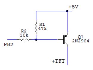
- Highsideswitch.JPG (13.47 KiB) Viewed 469 times
PNP doesn’t seem to work with that schematic
A falstad circuit using a PNP, if you swap out the PNP for an NPN, it seems to alternate between 1.6 v and 5.
https://goo.gl/4n91QE
I personally like more the P-Chan MOSFETs, they are easier to saturate.
A falstad circuit using a PNP, if you swap out the PNP for an NPN, it seems to alternate between 1.6 v and 5.
https://goo.gl/4n91QE
EDIT1:
It is worth to say that I have connected to my maple mini tft with sd and nrf24l01+ and when I disable any operation in my code responsible for nrf24l01 in the software it is not blinking.
EDIT2:
It seems that radio.flush(); from Enrf24 library is responsible for that because If I disable it everything works fine. Any Idea why?
That is because the PB2 output (when not configured as the open drain) gives 0..3.3V, and the emitter (source) of the PNP high side switch is at 5V. Therefore there is still 1.7V (=5-3.3) remaining between PB2 and the emitter (source) thus the PNP or Pmosfet will be not closed fully (you will not get 0V at TFT+).
Other option is to use an NPN transistor as a driver of the high-side PNP switch (see below).
EDIT: Always USE A 100ohm resitor in series with the display’s LEDs.
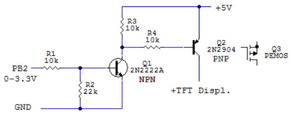
- NPN driver and PNP high side switch.JPG (21.8 KiB) Viewed 427 times
(But it does take some getting used to, ie to setup the simulation stuff)
pinMode(PB2,OUTPUT_OPEN_DRAIN); // in setup()
then the first circuit variant should work.
The blinking very strongly looks like power supply is colapsing when calling radio chip function.
Try to power the radio chip separately.
What does it do if you add a weak pull down (47K, or 100K or even larger) on that pin to GND?
What if you add a 1uf capacitor between the pin and GND?
What if you add a weak pull up to that pin?
Have you checked the soldering on the display? One of the ones I had was dreadful, and would blank out, show a white display, flicker and do all sorts of weird stuff, until I touched up the soldering and cleaned off the humongous quantities of flux residue.
2. Maybe te expensive one is able to switch off the backlight by register? I’ve seen in datascheet from ili9241 that it is possible. What do You think? How to do that ? https://cdn-shop.adafruit.com/datasheets/ILI9341.pdf starting from page no 169
Some use only 1 pin called LED (positive).
On the pcb there are 4-6 LEDs wired in serial/parallel combination.
2pins:
The positive pin must be connected to +TFT on the above schematics (collector or drain of the PNP or PMOS high side switch) via say 100ohm resistor in series.
DO NOT wire the backlight LEDs without a limiting resistor!! There is NONE resistor on the display’s pcb.
The negative pin should be connected to GND.
1pin called LED:
The pin must be connected to +TFT on the above schematics (collector or drain of the PNP or PMOS high side switch) via say 100ohm resistor in series.
DO NOT wire the backlight LEDs without a limiting resistor!! There is NONE resistor on the display’s pcb.
The negative pin is wired to GND on the display’s pcb.
I cannot see the hardware connection part where you control the backlight…
Is it port pin PB2 of the STM32? It seems to be used already as data pin D2.
Which pin of the LCD board do you control for backlight? The 5V pin? It seems that it is already used to supply the 3V3 for SD…
The problem is, we don’t know exactly how the schematic of the board looks like.
I would desolder the small 3.3V adapter from the board and supply the 3.3V from STM32 board. Moreover, you need to make a short from the 3.3V pin of the LCD board to the 3.3V line (adapter output) on the board, because, as far as I know, there is no connection per default.
Pin 12 (PC15) is giving High and Low to the base of PNP transistor.
How does the signal look like? Do you set it high and low intermittently in the main loop? Where exactly (relative to other sw functions)? How fast?
Your circuit is ok. You do not need the 4k7 resistor to ground. Let the 120ohm in series with +TFT (before leds). The white screen a little bit dimmed is ok. That means you do not have any graphics displayed.
PC15 has to be configured as an open drain output. With standard push-pull output it may not work properly (see my previous post). Again: Open Drain output PC15 with your above high side PNP switch.
PS: we really need to know at least your board’s link at ebay or better the schematics. It may happen your display has got only +5V VCC, and a 3.3V voltage regulator on it. The LEDs positive anodes could be connected to 5V or 3.3V internally and the LEDs negative cathodes are connected to a LED_GND pin. The second GND pin could be the master GND. Then you have to use low side NPN switch, collector connected to LED_GND via 120ohm resistor.
With single +5V on the board you will switch entire board off/on with the high side PNP switch.
Weird, isn’t it?
With the NPN low side switch the PC15 must stay standard output (not open drain).
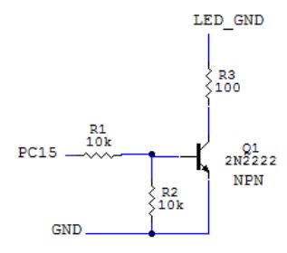
- low side led switch.JPG (14.95 KiB) Viewed 747 times
I personally find very strange, that the SD-adapter on the LCD board is working without being supplied either from 5V or 3.3V.
I could be wrong but I think it is powered from other pins
I’ve tried to power screen via 3.3V (not by the pin but directly to the voltage regulator 3.3v output) but it is still blinking
How does the signal look like?
I’ve made a timer with millis() which is counting down 6 sec and after that it is switching off the screen then if I touch the screen it is powering on and starts the countdown for off.
The white screen a little bit dimmed is ok. That means you do not have any graphics displayed
I’m afraid that in my case this is not true because if I’m not putting this resistor graphics is being shown and with this resistor it is not. Of course while using that circuit.
Open Drain output PC15
I have tried that already with pnp transistor but this didn’t change anything
The second GND pin could be the master GND. Then you have to use low side NPN switch, collector connected to LED_GND via 120ohm resistor.
Both GND pins are connected at the same point and it doesn’t matter which I connect. There is no LED_GND there is only one GND.
I have also tried PNP driven by NPN but no change
But there is another thing I have noticed. Then I take out sd card from sd slot it stops blinking :/
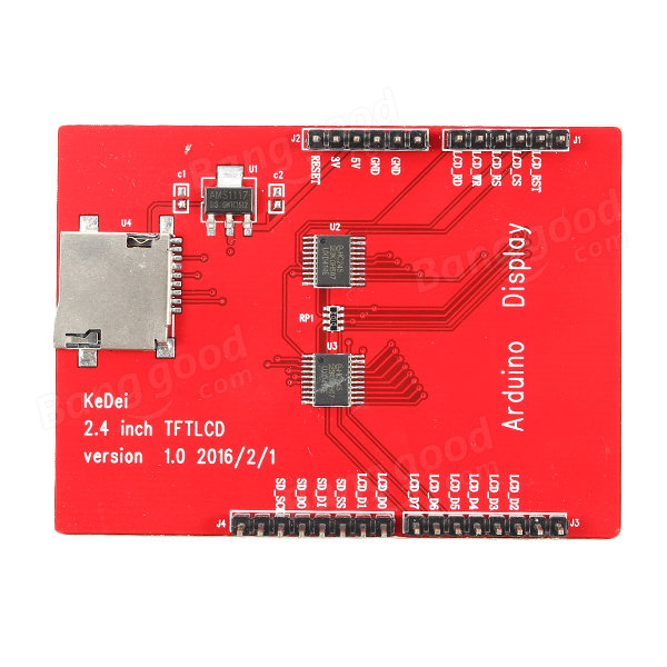
- Display.jpg (94.63 KiB) Viewed 724 times
Display.jpg
It has a couple of 74HC245 tri-state buffers on it, so may multiplex the display signals in some strange way
I know but I have no idea how to track which is the backlight connection. If we will not be able to get this done I think the only way will be to destroy the shield and check all the paths on the board to see which is which ![]()
it is not OK that you don’t give any dedicated power supply to LCD. It seems that now you are supplying the LCD board over the data/control pins from the STM32.
You should feed the LCD board with the 3.3V from STM32, with additional wire soldered between LCD bord pin 3V3 and the 5V<>3.3V power adaptor output (3.3V) pin. This wouldn’t be normally needed, but if you want to control the 5V, you have no other alternative.
If you don’t do this, it is normal that the power collapses when SD card is accessed, it needs some high current pulses when writing/reading data. If you take the SD card out, it will work.
https://forum.arduino.cc/index.php?topi … msg2451927
https://forum.arduino.cc/index.php?topi … msg2451875
the guys say the backlight cannot be switched off, you have to hack the board as the backlight is hardwired.
Also there is a warning in the above thread the 5V signals (or 5V Vcc??) may *propagate via 245 buffers onto sdcard’s VCC (somebody measured up to 4.3V on the sdcard’s socket).
https://forum.arduino.cc/index.php?topi … msg1764859
I would therefore not use 5V, but 3.3V Vcc only. And 3.3V signals, of course.
*Pito: It is possible via the clamping protection diodes each cmos device gets on its inputs/outputs.
It points here -> https://kedei.world.taobao.com/ <- for the manufacturers taobao page.
Let’s get back to LED on/off. With this screen I would have to cut the bold path (see magnified section) and solder a tiny wire to make a control via PNP transistor. In way that was described before. This will allow me to switch on/off backlight leds but it will still be blinking because of the sd card. Second problem is not to break the screen while disassembly
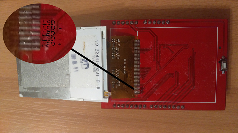
- TFT.jpg (134.31 KiB) Viewed 886 times
Thanks for dicovering the backlight control possibilty, i may use it later some time.
..for example the NPN low side switch in the schematics below. There is no other better circuit, afaik..
http://www.stm32duino.com/viewtopic.php … 220#p18680
Low at PC12 switches LEDs off, 3.3V High switches LEDs on. Simply cut off the gnd side trace of the LED’s resistor on the board, and wire the gnd side of the resistor to the collector of the NPN transistor. What value of the resistor they use on the board?
If you want to use fast PWM you may decrease the R1 and R2 to say 3k3.
TFT screen had 2.2 Ω but I’ve changed it to 5 Ω so in this circuit instead 100 Ω I gave 5 Ω and it’s working perfectly!
Even 5 Ω sounds a little excessive, have you tried measuring the current through your 5 Ω resistor, I suspect it will be of the order of 660 mA. All of this assumes there is no other current limiting resistor of course, which seems likely given the boards tendency to brown out the PSU. I would think that 22 Ω might be a more sane value as this would limit the per LED current to around 40mA and a potential maximum of around 165mA if things go a little pear shaped and one LED fails short circuit.
If you cannot measure the current through the resistor directly, measure the voltage drop across it, and fire it through Ohms law (I=V/R)
EDIT: In all of the above, I am assuming a perfect transistor, and the driver transistor turns fully on, and that the LED voltage is typical of a white LED, somewhere between 3.0 and 3.3V.
There are issues with these assumptions, and with driving four LEDs in parallel from one resistor. It will normally work, but there is a much higher risk of popping one, or all of them (due to thermal runaway of one over driven LED), if you drive them hard, than there would be if there were a current limiting resistor per LED.
Even if you are driving them with PWM, if the resistor value is too low, you still risk brown out of your PSU thus causing the LEDs to flicker and/or the CPU to crash. Also if you drive the voltage regulator too hard or cause the LEDs to start to break down by overheating you may release the magic smoke from both the LEDs and the regulator.
If you drive the LEDs without the transistor (using short On, long Off PWM pulses and a suitable single resistor), this may work, but you risk blowing up the GPIO pin if your chosen resistor allows more than the maximum GPIO current if the LED fails short circuit. ![]() You wont be able to drive them as hard, without the transistor of course.
You wont be able to drive them as hard, without the transistor of course.
I am also assuming four LEDs, there may only be two, in which case… we need to do the maths for two. ![]()
EDIT2: I have just spotted that whoever designed the actual display knew what they were doing, as they have brought out all four LED cathodes, to allow for four current limiting resistors. A much saner option than paralleling up all four LEDs, but the shield designer has cheaped out by wiring the cathodes together, thus limiting your option to only one current limiting resistor.
As the first LEDs appeared in seventies the rule was 20mA. They were all red, with Vf something like 1.6V and with 5V all used 150 to 200ohm.
Interestingly, the majority of designers especially of cheapo boards are following this 200ohm paradigm (or 10-20mA per LED), even today.
I did a measurement on about 20 various LEDs (mostly smd ones, all colors) from my junkbox to see how much current you need today in order to have an LED as “the indicator” of ON/OFF. The most LEDs are fine with 0.1mA for normal usage as indicator of a state. That leads to resistors of many kiloohms value. The clever designers adopted 1k resistors recently, but still the brightness is so high that in the ambient conditions you cannot see the buttons because of the brightness of the LEDs on the pcb
The LEDs differ significantly in the Vf and in If/brightness so the measurement is the only way to have an idea on the current vs. required brightness. If OP would experiment he sees the display works fine with maybe 10mA or less
This trick, coupled with low power modes on the CPU can extend the battery life from a few hours to weeks or even months.
TFT_DATA->regs->BSRR = ((~c)<<16) | (c); //Set pins to the 8 bit number
Do not buy fakes
S6D0154 -> TFT8K3654
http://uploads.ru/9PXAb.jpg
SPFD5408-> CK241_REV0.1
http://s0.uploads.ru/t/9PXAb.jpg
Read Registers on MCUFRIEND UNO shield

controllers either read as single 16-bit

e.g. the ID is at readReg(0)

or as a sequence of 8-bit values

in special locations (first is dummy)
reg(0x0000) 01 54 ID: ILI9320, ILI9325, ILI9335, ...
reg(0x0004) 00 00 00 00 Manufacturer ID
reg(0x0009) 00 1E 00 00 00 Status Register
reg(0x000A) 00 00 Get Power Mode
reg(0x000C) 00 00 Get Pixel Format
reg(0x0061) 00 00 RDID1 HX8347-G
reg(0x0062) 00 00 RDID2 HX8347-G
reg(0x0063) 00 00 RDID3 HX8347-G
reg(0x0064) 00 00 RDID1 HX8347-A
reg(0x0065) 00 00 RDID2 HX8347-A
reg(0x0066) 00 00 RDID3 HX8347-A
reg(0x0067) 00 00 RDID Himax HX8347-A
reg(0x0070) 00 00 Panel Himax HX8347-A
reg(0x00A1) 00 00 00 00 00 RD_DDB SSD1963
reg(0x00B0) 00 00 RGB Interface Signal Control
reg(0x00B4) 00 00 Inversion Control
reg(0x00B6) 00 00 00 00 00 Display Control
reg(0x00B7) 00 00 Entry Mode Set
reg(0x00BF) 00 00 00 00 00 00 ILI9481, HX8357-B
reg(0x00C0) 00 00 00 00 00 00 00 00 00 Panel Control
reg(0x00C8) 00 00 00 00 00 00 00 00 00 00 00 00 00 GAMMA
reg(0x00CC) 00 00 Panel Control
reg(0x00D0) 00 00 00 Power Control
reg(0x00D2) 00 00 00 00 00 NVM Read
reg(0x00D3) 00 00 00 00 ILI9341, ILI9488
reg(0x00D4) 00 00 00 00 Novatek ID
reg(0x00DA) 00 00 RDID1
reg(0x00DB) 00 00 RDID2
reg(0x00DC) 00 00 RDID3
reg(0x00E0) 00 00 00 00 00 00 00 00 00 00 00 00 00 00 00 00 GAMMA-P
reg(0x00E1) 00 00 00 00 00 00 00 00 00 00 00 00 00 00 00 00 GAMMA-N
reg(0x00EF) 00 00 00 00 00 00 ILI9327
reg(0x00F2) 00 00 00 00 00 00 00 00 00 00 00 00 Adjust Control 2
reg(0x00F6) 00 00 00 00 Interface Control
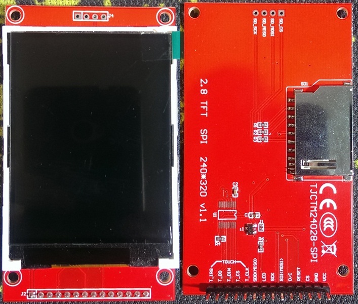
(found on google immage)
i tried the library from stevstrong
https://github.com/stevstrong/Adafruit_ … 8bit_STM32
but i didn’t manage to make it working
i used the connection in the Adafruit_TFTLCD_8bit_STM32.h file and for the SPI:
TFT_RS PA2
TFT_CS PA3
TFT_RST PB10
MOSI PA7
SCK PA5
LED +3.3V
MISO PA6
i didn’t connect the touch part and DC pin, since i don’t know where i should wire them
and what are these?
TFT_WR PA1
TFT_RD PA0
Your display has an SPI interface, and not an 8 bit parallel one.
So you should use this lib: https://github.com/rogerclarkmelbourne/ … LI9341_STM
Maybe also relevant: viewtopic.php?f=9&t=2425
[stevestrong – Wed Aug 30, 2017 7:36 am] –
You are posting in the wrong thread.
Your display has an SPI interface, and not an 8 bit parallel one.
So you should use this lib: https://github.com/rogerclarkmelbourne/ … LI9341_STM
Maybe also relevant: viewtopic.php?f=9&t=2425
not only i posted in the wrong thread but also i have been so stupid to not notice that the library i was looking for was already in the repo ![]()
now i am using your library thanks
it worked and compiled immediately, for some reason i can’t use PA4 as CS but i think this is an already know problem
[aster – Wed Aug 30, 2017 2:31 pm] – for some reason i can’t use PA4 as CS but i think this is an already know problem
Problem? Where?
I always use PA4 as CS without any problem…
[stevestrong – Wed Aug 30, 2017 2:42 pm] –
Problem? Where?
I always use PA4 as CS without any problem…
i think that i read that it had problem with sdfat, i am not sure
I don’t know i tried to connect cs to PA4 and it didn’t work then using another pin it worker
#define DC_pin PA1

#define RST_pin PA0

#define CS_pin PA2

/*

CS PA4

SCK PA5

MISO PA6

MOSI PA7

*/

Adafruit_ILI9341_STM tft(CS_pin, DC_pin, RST_pin); // input chip select, DC and reset pins
It may not be defined to PA0, because this translates to value 0:
https://github.com/rogerclarkmelbourne/ … oard.h#L80
and then the RST pin will not be toggled:
https://github.com/stevstrong/Arduino_S … TM.cpp#L78
I think I should correct the software to test for “>=0”.
Till then try to use any other pin for RST.
And, as I told, PA4 should work as CS. To check that, write a simple test program to toggle it.
i am happy my bad luck helped you spotted a small error in the library
by the way the problem with PA4 i was referring was this: viewtopic.php?f=44&p=33802#p33802 but looks like it was solved time ago
Now i thinks it is better to stop spamming this thread and maybe an admin could move these last post in the correct one
Hello.
I can not initialize the display ili9431 16-bit. Only the white screen appears.
Tell me please what I’m doing wrong?
Use the stm32f103c8t6 blue board + Arduino IDE 1.8.4 + Arduino_STM32 + library Adafruit_TFTLCD_16bit_STM32 (//#define USE_FSMC 1 in Adafruit_TFTLCD_16bit_STM32.h) + the sketch
Connection:
D0…D15 – PB0…15 (PB2 – removed the jumper and connected to pin)
WR, RS, CS – PA1,PA2,PA3
RST – PC15
RD – connected to 3.3v and GND
If I use the library Adafruit_ILI9341_8bit_STM (iwalpola) with recommended connection pins, the image appears, but only used the blue color and its shades.
P.S.
Wrote the text using google translate from Russian language
1. the line https://github.com/stevstrong/Adafruit_ … M32.h#L103
to
#if 1
[stevestrong – Thu Oct 26, 2017 8:38 am] –
2. In line https://github.com/stevstrong/Adafruit_ … M32.h#L149
replace Adafruit_GFX by “Adafruit_GFX_AS“Do you get any warnings during build?
In file included from C:\Users\MAKC-admin\Desktop\arduino-1.8.4\hardware\Arduino_STM32-master\STM32F1\libraries\Adafruit_TFTLCD_16bit_STM32-master\examples\graphicstest\graphicstest.ino:7:0:
C:\Users\MAKC-admin\Desktop\arduino-1.8.4\hardware\Arduino_STM32-master\STM32F1\libraries\Adafruit_TFTLCD_16bit_STM32-master\src/Adafruit_TFTLCD_16bit_STM32.h:149:60: error: expected class-name before '{' token
class Adafruit_TFTLCD_16bit_STM32 : public Adafruit_GFX_AS {
^
C:\Users\MAKC-admin\Desktop\arduino-1.8.4\hardware\Arduino_STM32-master\STM32F1\libraries\Adafruit_TFTLCD_16bit_STM32-master\examples\graphicstest\graphicstest.ino: In function 'void setup()':
graphicstest:20: error: 'class Adafruit_TFTLCD_16bit_STM32' has no member named 'width'
Serial.print("TFT size is "); Serial.print((uint16_t)tft.width()); Serial.print("x"); Serial.println((uint16_t)tft.height());
^
graphicstest:20: error: 'class Adafruit_TFTLCD_16bit_STM32' has no member named 'height'
Serial.print("TFT size is "); Serial.print((uint16_t)tft.width()); Serial.print("x"); Serial.println((uint16_t)tft.height());
^
C:\Users\MAKC-admin\Desktop\arduino-1.8.4\hardware\Arduino_STM32-master\STM32F1\libraries\Adafruit_TFTLCD_16bit_STM32-master\examples\graphicstest\graphicstest.ino: In function 'long unsigned int testText()':
graphicstest:179: error: 'class Adafruit_TFTLCD_16bit_STM32' has no member named 'setCursor'
tft.setCursor(0, 0);
^
graphicstest:180: error: 'class Adafruit_TFTLCD_16bit_STM32' has no member named 'setTextColor'
tft.setTextColor(WHITE); tft.setTextSize(1);
^
graphicstest:180: error: 'class Adafruit_TFTLCD_16bit_STM32' has no member named 'setTextSize'
tft.setTextColor(WHITE); tft.setTextSize(1);
^
graphicstest:181: error: 'class Adafruit_TFTLCD_16bit_STM32' has no member named 'println'
tft.println("Hello World!");
^
graphicstest:182: error: 'class Adafruit_TFTLCD_16bit_STM32' has no member named 'setTextColor'
tft.setTextColor(YELLOW); tft.setTextSize(2);
^
graphicstest:182: error: 'class Adafruit_TFTLCD_16bit_STM32' has no member named 'setTextSize'
tft.setTextColor(YELLOW); tft.setTextSize(2);
^
graphicstest:183: error: 'class Adafruit_TFTLCD_16bit_STM32' has no member named 'println'
tft.println(1234.56);
^
graphicstest:184: error: 'class Adafruit_TFTLCD_16bit_STM32' has no member named 'setTextColor'
tft.setTextColor(RED); tft.setTextSize(3);
^
graphicstest:184: error: 'class Adafruit_TFTLCD_16bit_STM32' has no member named 'setTextSize'
tft.setTextColor(RED); tft.setTextSize(3);
^
graphicstest:185: error: 'class Adafruit_TFTLCD_16bit_STM32' has no member named 'println'
tft.println(0xDEADBEEF, HEX);
^
graphicstest:186: error: 'class Adafruit_TFTLCD_16bit_STM32' has no member named 'println'
tft.println();
^
graphicstest:187: error: 'class Adafruit_TFTLCD_16bit_STM32' has no member named 'setTextColor'
tft.setTextColor(GREEN);
^
graphicstest:188: error: 'class Adafruit_TFTLCD_16bit_STM32' has no member named 'setTextSize'
tft.setTextSize(5);
^
graphicstest:189: error: 'class Adafruit_TFTLCD_16bit_STM32' has no member named 'println'
tft.println("Groop");
^
graphicstest:190: error: 'class Adafruit_TFTLCD_16bit_STM32' has no member named 'setTextSize'
tft.setTextSize(2);
^
graphicstest:191: error: 'class Adafruit_TFTLCD_16bit_STM32' has no member named 'println'
tft.println("I implore thee,");
^
graphicstest:192: error: 'class Adafruit_TFTLCD_16bit_STM32' has no member named 'setTextSize'
tft.setTextSize(1);
^
graphicstest:193: error: 'class Adafruit_TFTLCD_16bit_STM32' has no member named 'println'
tft.println("my foonting turlingdromes.");
^
graphicstest:194: error: 'class Adafruit_TFTLCD_16bit_STM32' has no member named 'println'
tft.println("And hooptiously drangle me");
^
graphicstest:195: error: 'class Adafruit_TFTLCD_16bit_STM32' has no member named 'println'
tft.println("with crinkly bindlewurdles,");
^
graphicstest:196: error: 'class Adafruit_TFTLCD_16bit_STM32' has no member named 'println'
tft.println("Or I will rend thee");
^
graphicstest:197: error: 'class Adafruit_TFTLCD_16bit_STM32' has no member named 'println'
tft.println("in the gobberwarts");
^
graphicstest:198: error: 'class Adafruit_TFTLCD_16bit_STM32' has no member named 'println'
tft.println("with my blurglecruncheon,");
^
graphicstest:199: error: 'class Adafruit_TFTLCD_16bit_STM32' has no member named 'println'
tft.println("see if I don't!");
^
C:\Users\MAKC-admin\Desktop\arduino-1.8.4\hardware\Arduino_STM32-master\STM32F1\libraries\Adafruit_TFTLCD_16bit_STM32-master\examples\graphicstest\graphicstest.ino: In function 'long unsigned int testLines(uint16_t)':
graphicstest:206: error: 'class Adafruit_TFTLCD_16bit_STM32' has no member named 'width'
w = tft.width(),
^
graphicstest:212: error: 'h' was not declared in this scope
y2 = h - 1;
^
graphicstest:214: error: 'class Adafruit_TFTLCD_16bit_STM32' has no member named 'drawLine'
for(x2=0; x2<w; x2+=6) tft.drawLine(x1, y1, x2, y2, color);
^
graphicstest:216: error: 'class Adafruit_TFTLCD_16bit_STM32' has no member named 'drawLine'
for(y2=0; y2<h; y2+=6) tft.drawLine(x1, y1, x2, y2, color);
^
graphicstest:225: error: 'class Adafruit_TFTLCD_16bit_STM32' has no member named 'drawLine'
for(x2=0; x2<w; x2+=6) tft.drawLine(x1, y1, x2, y2, color);
^
graphicstest:227: error: 'class Adafruit_TFTLCD_16bit_STM32' has no member named 'drawLine'
for(y2=0; y2<h; y2+=6) tft.drawLine(x1, y1, x2, y2, color);
^
graphicstest:236: error: 'class Adafruit_TFTLCD_16bit_STM32' has no member named 'drawLine'
for(x2=0; x2<w; x2+=6) tft.drawLine(x1, y1, x2, y2, color);
^
graphicstest:238: error: 'class Adafruit_TFTLCD_16bit_STM32' has no member named 'drawLine'
for(y2=0; y2<h; y2+=6) tft.drawLine(x1, y1, x2, y2, color);
^
graphicstest:247: error: 'class Adafruit_TFTLCD_16bit_STM32' has no member named 'drawLine'
for(x2=0; x2<w; x2+=6) tft.drawLine(x1, y1, x2, y2, color);
^
graphicstest:249: error: 'class Adafruit_TFTLCD_16bit_STM32' has no member named 'drawLine'
for(y2=0; y2<h; y2+=6) tft.drawLine(x1, y1, x2, y2, color);
^
C:\Users\MAKC-admin\Desktop\arduino-1.8.4\hardware\Arduino_STM32-master\STM32F1\libraries\Adafruit_TFTLCD_16bit_STM32-master\examples\graphicstest\graphicstest.ino: In function 'long unsigned int testFastLines(uint16_t, uint16_t)':
graphicstest:256: error: 'class Adafruit_TFTLCD_16bit_STM32' has no member named 'width'
int x, y, w = tft.width(), h = tft.height();
^
graphicstest:260: error: 'h' was not declared in this scope
for(y=0; y<h; y+=5) tft.drawFastHLine(0, y, w, color1);
^
graphicstest:261: error: 'h' was not declared in this scope
for(x=0; x<w; x+=5) tft.drawFastVLine(x, 0, h, color2);
^
C:\Users\MAKC-admin\Desktop\arduino-1.8.4\hardware\Arduino_STM32-master\STM32F1\libraries\Adafruit_TFTLCD_16bit_STM32-master\examples\graphicstest\graphicstest.ino: In function 'long unsigned int testRects(uint16_t)':
graphicstest:269: error: 'class Adafruit_TFTLCD_16bit_STM32' has no member named 'width'
cx = tft.width() / 2,
^
In file included from C:\Users\MAKC-admin\Desktop\arduino-1.8.4\hardware\Arduino_STM32-master\STM32F1\cores\maple/wirish.h:60:0,
from C:\Users\MAKC-admin\Desktop\arduino-1.8.4\hardware\Arduino_STM32-master\STM32F1\cores\maple/Arduino.h:30,
from C:\Users\MAKC-admin\Desktop\arduino-1.8.4\hardware\Arduino_STM32-master\STM32F1\libraries\Adafruit_TFTLCD_16bit_STM32-master\examples\graphicstest\graphicstest.ino:1:
graphicstest:273: error: 'class Adafruit_TFTLCD_16bit_STM32' has no member named 'width'
n = min(tft.width(), tft.height());
^
C:\Users\MAKC-admin\Desktop\arduino-1.8.4\hardware\Arduino_STM32-master\STM32F1\cores\maple/wirish_math.h:108:35: note: in definition of macro 'min'
#define min(a,b) ((a)<(b)?(a):(b))
^
graphicstest:273: error: 'class Adafruit_TFTLCD_16bit_STM32' has no member named 'height'
n = min(tft.width(), tft.height());
^
C:\Users\MAKC-admin\Desktop\arduino-1.8.4\hardware\Arduino_STM32-master\STM32F1\cores\maple/wirish_math.h:108:39: note: in definition of macro 'min'
#define min(a,b) ((a)<(b)?(a):(b))
^
graphicstest:273: error: 'class Adafruit_TFTLCD_16bit_STM32' has no member named 'width'
n = min(tft.width(), tft.height());
^
C:\Users\MAKC-admin\Desktop\arduino-1.8.4\hardware\Arduino_STM32-master\STM32F1\cores\maple/wirish_math.h:108:43: note: in definition of macro 'min'
#define min(a,b) ((a)<(b)?(a):(b))
^
graphicstest:273: error: 'class Adafruit_TFTLCD_16bit_STM32' has no member named 'height'
n = min(tft.width(), tft.height());
^
C:\Users\MAKC-admin\Desktop\arduino-1.8.4\hardware\Arduino_STM32-master\STM32F1\cores\maple/wirish_math.h:108:47: note: in definition of macro 'min'
#define min(a,b) ((a)<(b)?(a):(b))
^
graphicstest:277: error: 'class Adafruit_TFTLCD_16bit_STM32' has no member named 'drawRect'
tft.drawRect(cx-i2, cy-i2, i, i, color);
^
graphicstest:277: error: 'cy' was not declared in this scope
tft.drawRect(cx-i2, cy-i2, i, i, color);
^
C:\Users\MAKC-admin\Desktop\arduino-1.8.4\hardware\Arduino_STM32-master\STM32F1\libraries\Adafruit_TFTLCD_16bit_STM32-master\examples\graphicstest\graphicstest.ino: In function 'long unsigned int testFilledRects(uint16_t, uint16_t)':
graphicstest:286: error: 'class Adafruit_TFTLCD_16bit_STM32' has no member named 'width'
cx = tft.width() / 2 - 1,
^
In file included from C:\Users\MAKC-admin\Desktop\arduino-1.8.4\hardware\Arduino_STM32-master\STM32F1\cores\maple/wirish.h:60:0,
from C:\Users\MAKC-admin\Desktop\arduino-1.8.4\hardware\Arduino_STM32-master\STM32F1\cores\maple/Arduino.h:30,
from C:\Users\MAKC-admin\Desktop\arduino-1.8.4\hardware\Arduino_STM32-master\STM32F1\libraries\Adafruit_TFTLCD_16bit_STM32-master\examples\graphicstest\graphicstest.ino:1:
graphicstest:290: error: 'class Adafruit_TFTLCD_16bit_STM32' has no member named 'width'
n = min(tft.width(), tft.height());
^
C:\Users\MAKC-admin\Desktop\arduino-1.8.4\hardware\Arduino_STM32-master\STM32F1\cores\maple/wirish_math.h:108:35: note: in definition of macro 'min'
#define min(a,b) ((a)<(b)?(a):(b))
^
graphicstest:290: error: 'class Adafruit_TFTLCD_16bit_STM32' has no member named 'height'
n = min(tft.width(), tft.height());
^
C:\Users\MAKC-admin\Desktop\arduino-1.8.4\hardware\Arduino_STM32-master\STM32F1\cores\maple/wirish_math.h:108:39: note: in definition of macro 'min'
#define min(a,b) ((a)<(b)?(a):(b))
^
graphicstest:290: error: 'class Adafruit_TFTLCD_16bit_STM32' has no member named 'width'
n = min(tft.width(), tft.height());
^
C:\Users\MAKC-admin\Desktop\arduino-1.8.4\hardware\Arduino_STM32-master\STM32F1\cores\maple/wirish_math.h:108:43: note: in definition of macro 'min'
#define min(a,b) ((a)<(b)?(a):(b))
^
graphicstest:290: error: 'class Adafruit_TFTLCD_16bit_STM32' has no member named 'height'
n = min(tft.width(), tft.height());
^
C:\Users\MAKC-admin\Desktop\arduino-1.8.4\hardware\Arduino_STM32-master\STM32F1\cores\maple/wirish_math.h:108:47: note: in definition of macro 'min'
#define min(a,b) ((a)<(b)?(a):(b))
^
graphicstest:294: error: 'cy' was not declared in this scope
tft.fillRect(cx-i2, cy-i2, i, i, color1);
^
graphicstest:297: error: 'class Adafruit_TFTLCD_16bit_STM32' has no member named 'drawRect'
tft.drawRect(cx-i2, cy-i2, i, i, color2);
^
C:\Users\MAKC-admin\Desktop\arduino-1.8.4\hardware\Arduino_STM32-master\STM32F1\libraries\Adafruit_TFTLCD_16bit_STM32-master\examples\graphicstest\graphicstest.ino: In function 'long unsigned int testFilledCircles(uint8_t, uint16_t)':
graphicstest:305: error: 'class Adafruit_TFTLCD_16bit_STM32' has no member named 'width'
int x, y, w = tft.width(), h = tft.height(), r2 = radius * 2;
^
graphicstest:309: error: 'r2' was not declared in this scope
for(x=radius; x<w; x+=r2) {
^
graphicstest:310: error: 'h' was not declared in this scope
for(y=radius; y<h; y+=r2) {
^
graphicstest:311: error: 'class Adafruit_TFTLCD_16bit_STM32' has no member named 'fillCircle'
tft.fillCircle(x, y, radius, color);
^
C:\Users\MAKC-admin\Desktop\arduino-1.8.4\hardware\Arduino_STM32-master\STM32F1\libraries\Adafruit_TFTLCD_16bit_STM32-master\examples\graphicstest\graphicstest.ino: In function 'long unsigned int testCircles(uint8_t, uint16_t)':
graphicstest:321: error: 'class Adafruit_TFTLCD_16bit_STM32' has no member named 'width'
w = tft.width() + radius,
^
graphicstest:328: error: 'h' was not declared in this scope
for(y=0; y<h; y+=r2) {
^
graphicstest:329: error: 'class Adafruit_TFTLCD_16bit_STM32' has no member named 'drawCircle'
tft.drawCircle(x, y, radius, color);
^
C:\Users\MAKC-admin\Desktop\arduino-1.8.4\hardware\Arduino_STM32-master\STM32F1\libraries\Adafruit_TFTLCD_16bit_STM32-master\examples\graphicstest\graphicstest.ino: In function 'long unsigned int testTriangles()':
graphicstest:338: error: 'class Adafruit_TFTLCD_16bit_STM32' has no member named 'width'
int n, i, cx = tft.width() / 2 - 1,
^
In file included from C:\Users\MAKC-admin\Desktop\arduino-1.8.4\hardware\Arduino_STM32-master\STM32F1\cores\maple/wirish.h:60:0,
from C:\Users\MAKC-admin\Desktop\arduino-1.8.4\hardware\Arduino_STM32-master\STM32F1\cores\maple/Arduino.h:30,
from C:\Users\MAKC-admin\Desktop\arduino-1.8.4\hardware\Arduino_STM32-master\STM32F1\libraries\Adafruit_TFTLCD_16bit_STM32-master\examples\graphicstest\graphicstest.ino:1:
graphicstest:342: error: 'cy' was not declared in this scope
n = min(cx, cy);
^
C:\Users\MAKC-admin\Desktop\arduino-1.8.4\hardware\Arduino_STM32-master\STM32F1\cores\maple/wirish_math.h:108:39: note: in definition of macro 'min'
#define min(a,b) ((a)<(b)?(a):(b))
^
graphicstest:345: error: 'class Adafruit_TFTLCD_16bit_STM32' has no member named 'drawTriangle'
tft.drawTriangle(
^
C:\Users\MAKC-admin\Desktop\arduino-1.8.4\hardware\Arduino_STM32-master\STM32F1\libraries\Adafruit_TFTLCD_16bit_STM32-master\examples\graphicstest\graphicstest.ino: In function 'long unsigned int testFilledTriangles()':
graphicstest:357: error: 'class Adafruit_TFTLCD_16bit_STM32' has no member named 'width'
int i, cx = tft.width() / 2 - 1,
^
In file included from C:\Users\MAKC-admin\Desktop\arduino-1.8.4\hardware\Arduino_STM32-master\STM32F1\cores\maple/wirish.h:60:0,
from C:\Users\MAKC-admin\Desktop\arduino-1.8.4\hardware\Arduino_STM32-master\STM32F1\cores\maple/Arduino.h:30,
from C:\Users\MAKC-admin\Desktop\arduino-1.8.4\hardware\Arduino_STM32-master\STM32F1\libraries\Adafruit_TFTLCD_16bit_STM32-master\examples\graphicstest\graphicstest.ino:1:
graphicstest:362: error: 'cy' was not declared in this scope
for(i=min(cx,cy); i>10; i-=5) {
^
C:\Users\MAKC-admin\Desktop\arduino-1.8.4\hardware\Arduino_STM32-master\STM32F1\cores\maple/wirish_math.h:108:39: note: in definition of macro 'min'
#define min(a,b) ((a)<(b)?(a):(b))
^
graphicstest:364: error: 'class Adafruit_TFTLCD_16bit_STM32' has no member named 'fillTriangle'
tft.fillTriangle(cx, cy - i, cx - i, cy + i, cx + i, cy + i,
^
graphicstest:367: error: 'class Adafruit_TFTLCD_16bit_STM32' has no member named 'drawTriangle'
tft.drawTriangle(cx, cy - i, cx - i, cy + i, cx + i, cy + i,
^
C:\Users\MAKC-admin\Desktop\arduino-1.8.4\hardware\Arduino_STM32-master\STM32F1\libraries\Adafruit_TFTLCD_16bit_STM32-master\examples\graphicstest\graphicstest.ino: In function 'long unsigned int testRoundRects()':
graphicstest:377: error: 'class Adafruit_TFTLCD_16bit_STM32' has no member named 'width'
cx = tft.width() / 2 - 1,
^
In file included from C:\Users\MAKC-admin\Desktop\arduino-1.8.4\hardware\Arduino_STM32-master\STM32F1\cores\maple/wirish.h:60:0,
from C:\Users\MAKC-admin\Desktop\arduino-1.8.4\hardware\Arduino_STM32-master\STM32F1\cores\maple/Arduino.h:30,
from C:\Users\MAKC-admin\Desktop\arduino-1.8.4\hardware\Arduino_STM32-master\STM32F1\libraries\Adafruit_TFTLCD_16bit_STM32-master\examples\graphicstest\graphicstest.ino:1:
graphicstest:381: error: 'class Adafruit_TFTLCD_16bit_STM32' has no member named 'width'
w = min(tft.width(), tft.height());
^
C:\Users\MAKC-admin\Desktop\arduino-1.8.4\hardware\Arduino_STM32-master\STM32F1\cores\maple/wirish_math.h:108:35: note: in definition of macro 'min'
#define min(a,b) ((a)<(b)?(a):(b))
^
graphicstest:381: error: 'class Adafruit_TFTLCD_16bit_STM32' has no member named 'height'
w = min(tft.width(), tft.height());
^
C:\Users\MAKC-admin\Desktop\arduino-1.8.4\hardware\Arduino_STM32-master\STM32F1\cores\maple/wirish_math.h:108:39: note: in definition of macro 'min'
#define min(a,b) ((a)<(b)?(a):(b))
^
graphicstest:381: error: 'class Adafruit_TFTLCD_16bit_STM32' has no member named 'width'
w = min(tft.width(), tft.height());
^
C:\Users\MAKC-admin\Desktop\arduino-1.8.4\hardware\Arduino_STM32-master\STM32F1\cores\maple/wirish_math.h:108:43: note: in definition of macro 'min'
#define min(a,b) ((a)<(b)?(a):(b))
^
graphicstest:381: error: 'class Adafruit_TFTLCD_16bit_STM32' has no member named 'height'
w = min(tft.width(), tft.height());
^
C:\Users\MAKC-admin\Desktop\arduino-1.8.4\hardware\Arduino_STM32-master\STM32F1\cores\maple/wirish_math.h:108:47: note: in definition of macro 'min'
#define min(a,b) ((a)<(b)?(a):(b))
^
graphicstest:385: error: 'class Adafruit_TFTLCD_16bit_STM32' has no member named 'drawRoundRect'
tft.drawRoundRect(cx-i2, cy-i2, i, i, i/8, tft.color565(i, 0, 0));
^
graphicstest:385: error: 'cy' was not declared in this scope
tft.drawRoundRect(cx-i2, cy-i2, i, i, i/8, tft.color565(i, 0, 0));
^
C:\Users\MAKC-admin\Desktop\arduino-1.8.4\hardware\Arduino_STM32-master\STM32F1\libraries\Adafruit_TFTLCD_16bit_STM32-master\examples\graphicstest\graphicstest.ino: In function 'long unsigned int testFilledRoundRects()':
graphicstest:394: error: 'class Adafruit_TFTLCD_16bit_STM32' has no member named 'width'
cx = tft.width() / 2 - 1,
^
In file included from C:\Users\MAKC-admin\Desktop\arduino-1.8.4\hardware\Arduino_STM32-master\STM32F1\cores\maple/wirish.h:60:0,
from C:\Users\MAKC-admin\Desktop\arduino-1.8.4\hardware\Arduino_STM32-master\STM32F1\cores\maple/Arduino.h:30,
from C:\Users\MAKC-admin\Desktop\arduino-1.8.4\hardware\Arduino_STM32-master\STM32F1\libraries\Adafruit_TFTLCD_16bit_STM32-master\examples\graphicstest\graphicstest.ino:1:
graphicstest:399: error: 'class Adafruit_TFTLCD_16bit_STM32' has no member named 'width'
for(i=min(tft.width(), tft.height()); i>20; i-=6) {
^
C:\Users\MAKC-admin\Desktop\arduino-1.8.4\hardware\Arduino_STM32-master\STM32F1\cores\maple/wirish_math.h:108:35: note: in definition of macro 'min'
#define min(a,b) ((a)<(b)?(a):(b))
^
graphicstest:399: error: 'class Adafruit_TFTLCD_16bit_STM32' has no member named 'height'
for(i=min(tft.width(), tft.height()); i>20; i-=6) {
^
C:\Users\MAKC-admin\Desktop\arduino-1.8.4\hardware\Arduino_STM32-master\STM32F1\cores\maple/wirish_math.h:108:39: note: in definition of macro 'min'
#define min(a,b) ((a)<(b)?(a):(b))
^
graphicstest:399: error: 'class Adafruit_TFTLCD_16bit_STM32' has no member named 'width'
for(i=min(tft.width(), tft.height()); i>20; i-=6) {
^
C:\Users\MAKC-admin\Desktop\arduino-1.8.4\hardware\Arduino_STM32-master\STM32F1\cores\maple/wirish_math.h:108:43: note: in definition of macro 'min'
#define min(a,b) ((a)<(b)?(a):(b))
^
graphicstest:399: error: 'class Adafruit_TFTLCD_16bit_STM32' has no member named 'height'
for(i=min(tft.width(), tft.height()); i>20; i-=6) {
^
C:\Users\MAKC-admin\Desktop\arduino-1.8.4\hardware\Arduino_STM32-master\STM32F1\cores\maple/wirish_math.h:108:47: note: in definition of macro 'min'
#define min(a,b) ((a)<(b)?(a):(b))
^
graphicstest:401: error: 'class Adafruit_TFTLCD_16bit_STM32' has no member named 'fillRoundRect'
tft.fillRoundRect(cx-i2, cy-i2, i, i, i/8, tft.color565(0, i, 0));
^
graphicstest:401: error: 'cy' was not declared in this scope
tft.fillRoundRect(cx-i2, cy-i2, i, i, i/8, tft.color565(0, i, 0));
^
Используем библиотеку Adafruit_TFTLCD_16bit_STM32-master версии 1.0.0 из папки: C:\Users\MAKC-admin\Desktop\arduino-1.8.4\hardware\Arduino_STM32-master\STM32F1\libraries\Adafruit_TFTLCD_16bit_STM32-master
Используем библиотеку Adafruit_GFX_AS в папке: C:\Users\MAKC-admin\Desktop\arduino-1.8.4\hardware\Arduino_STM32-master\STM32F1\libraries\Adafruit_GFX_AS (legacy)
exit status 1
'class Adafruit_TFTLCD_16bit_STM32' has no member named 'width'
Change it back, please.
Have you tried 1.?
After a point 1 on a display nothing appeared(
I also have white screen with 16 bit library from Steve.
Did you checked the serial monitor?
My serial monitor prints out the test result just the lcd white.
Please replace 0x44444444 by 0x33333333, in both places.
Mode value 4 means input floating, value 3 means output 50MHz.
So the line should look like:
#define setWriteDir() { TFT_DATA_PORT->regs->CRL = 0x33333333; TFT_DATA_PORT->regs->CRH = 0x33333333; } // set the bits as output
[stevestrong – Thu Oct 26, 2017 7:26 pm] –
I think there is a simple reason why it is not working: there is bug here: https://github.com/stevstrong/Adafruit_ … M32.h#L138
Please replace 0x44444444 by 0x33333333, in both places.
Mode value 4 means input floating, value 3 means output 50MHz.So the line should look like:
#define setWriteDir() { TFT_DATA_PORT->regs->CRL = 0x33333333; TFT_DATA_PORT->regs->CRH = 0x33333333; } // set the bits as output
Commuted the mode of display controller on 8bit and used a library Adafruit_ILI9341_8bit_STM (iwalpola)
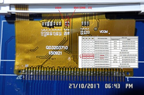
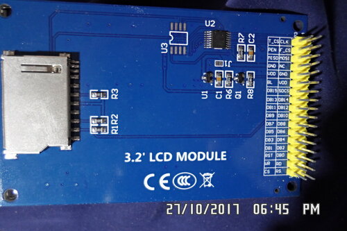
Connection:
//Port data |D15 |D14 |D13 |D12 |D11 |D10 |D9 |D8 |
//Pin stm32 |PA7|PA6|PA5|PA4|PA3|PA2|PA1|PA0|
//Control pins |RD |WR |RS |CS |RST|
//Pin stm32 |PB4|PB5|PB6|PB7|PB8|
Scheme shield and libraries for STM https://yadi.sk/d/sOkpTV6nmLxeU
stevestrong
Tried to connect on a chart:
PB0…PB15 – DB8…DB15, DB0…DB7 a display did not begin (white screen) to work
I have to find some time to connect it to BP and find out what is going wrong there.
it reports as an ILI9431 on the uno, it uses 8 data pins and 4 control lines + RST, but when connecting to the blue pill the screen remains white and serial outputs as it should
i have tried the standard library pinout connection (removed boot1 jumper and attached D2 to the centre pin)
Port data |D7 |D6 |D5 |D4 |D3 |D2 |D1 |D0 |

Pin stm32 |PB7|PB6|PB5|PB4|PB3|PB2|PB1|PB0|

Control pins |RD |WR |RS |CS |RST|

Pin stm32 |PA4|PA5|PA6|PA7|PA8|I will double check my setup at home in a couple of hours.
[stevestrong – Mon Dec 18, 2017 2:19 pm] –
If you use my lib, then you have to have all consecutive data pins in order from 0 to 7 (low nibble) or 8 to 15 (high nibble).
I will double check my setup at home in a couple of hours.
thanks steve, i thought that might be the case. i guess i didnt change the lib pinout, as i was only changing the #if 0 // slow write case..
should i be using #define USE_ADAFRUIT_SHIELD_PINOUT 1 ? edit: tried commented and uncommented, same results..
So now I suggest to test this LCD_ID test example from David to prove that the connections are ok.
And post here the serial monitor output.
#define LCD_RST PA4

#define LCD_CS PA3

#define LCD_RS PA2

#define LCD_WR PA1

#define LCD_RD PA0
#define LCD_D0 PB0

#define LCD_D1 PB1

#define LCD_D2 PB2

#define LCD_D3 PB3

#define LCD_D4 PB4

#define LCD_D5 PB5

#define LCD_D6 PB6

#define LCD_D7 PB7
Or your board has a failure.
Or PB2 does not work, you have to shorten the R4 resistor.
Read Registers on MCUFRIEND UNO shield

controllers either read as single 16-bit

e.g. the ID is at readReg(0)

or as a sequence of 8-bit values

in special locations (first is dummy)
reg(0x0000) 00 00 ID: ILI9320, ILI9325, ILI9335, ...
reg(0x0004) 00 00 00 00 Manufacturer ID
reg(0x0009) 00 00 00 00 00 Status Register
reg(0x000A) 00 00 Get Power Mode
reg(0x000C) 00 00 Get Pixel Format
reg(0x0061) 00 00 RDID1 HX8347-G
reg(0x0062) 00 00 RDID2 HX8347-G
reg(0x0063) 00 00 RDID3 HX8347-G
reg(0x0064) 00 00 RDID1 HX8347-A
reg(0x0065) 00 00 RDID2 HX8347-A
reg(0x0066) 00 00 RDID3 HX8347-A
reg(0x0067) 00 00 RDID Himax HX8347-A
reg(0x0070) 00 00 Panel Himax HX8347-A
reg(0x00A1) 00 00 13 13 13 RD_DDB SSD1963
reg(0x00B0) 00 00 RGB Interface Signal Control
reg(0x00B4) 00 44 Inversion Control
reg(0x00B6) 00 02 82 27 04 Display Control
reg(0x00B7) 00 06 Entry Mode Set
reg(0x00BF) 00 06 06 06 06 06 ILI9481, HX8357-B
reg(0x00C0) 00 00 00 00 00 00 00 00 00 Panel Control
reg(0x00C8) 00 00 00 00 00 00 00 00 00 00 00 00 00 GAMMA
reg(0x00CC) 00 00 Panel Control
reg(0x00D0) 00 00 00 Power Control
reg(0x00D2) 00 00 00 03 03 NVM Read
reg(0x00D3) 00 00 93 41 ILI9341, ILI9488
reg(0x00D4) 00 00 00 00 Novatek ID
reg(0x00DA) 00 00 RDID1
reg(0x00DB) 00 00 RDID2
reg(0x00DC) 00 00 RDID3
reg(0x00E0) 00 00 00 00 00 00 00 00 00 00 00 00 00 00 00 00 GAMMA-P
reg(0x00E1) 00 00 00 00 00 00 00 00 00 00 00 00 00 00 00 00 GAMMA-N
reg(0x00EF) 00 10 10 10 10 10 ILI9327
reg(0x00F2) 00 02 02 02 02 02 02 02 02 02 02 02 Adjust Control 2
reg(0x00F6) 00 01 00 00 Interface Control
ive just downloaded your latest version of the lib
changed #define TFT_RST PB10 to PA4 to match my wiring..
still get white screen only
graphicstest serial output: (but still with white screen only)
TFT size is 240x320

Found ILI9341 LCD driver

TFT begin done.

rotation: 0, runtime: 22047

rotation: 1, runtime: 22046

rotation: 2, runtime: 22046

rotation: 3, runtime: 22046
Benchmark Time (microseconds)
Screen fill 65196
Text 22046
Lines 177382
Horiz/Vert Lines 7988
Rectangles (outline) 6260
Rectangles (filled) 151869
Circles (filled) 97002
Circles (outline) 76594
Triangles (outline) 56363
Triangles (filled) 95581
Rounded rects (outline) 28134
Rounded rects (filled) 192794
Done!
But i have an 9341 compatible 16 bit LCD, I will check whether the register init sequence is ok.
edit: finally got around to removing and jumpering the R4 resistor thinking it would help…but it hasnt made any difference
im just gonna go buy a SPI TFT LCD..
Benchmark                Time (microseconds)

Screen fill              54843

Text                     23228

Lines                    423008

Horiz/Vert Lines         6840

Rectangles (outline)     5712

Rectangles (filled)      134003

Circles (filled)         187443

Circles (outline)        177951

Triangles (outline)      118043

Triangles (filled)       122780

Rounded rects (outline)  53757

Rounded rects (filled) 192710ive been using the default pinouts, just to get it working, triple checked the wiring, and even continuity tested each pin, but no luck getting anything onscreen…forcing #if 1 does run slower (the serial output) but still no onscreen output
its a strange LCD, the only lib i can make it work with on arduino is the MCUFRIEND_kbv library, the adafruit libs dont work as expected..
im just gonna buy a SPI LCD for the bluepill and keep this shield for the uno (its slower on mega than uno!)
edit: got it working on the bluepill with the latest MCUFRIEND lib ![]()
I have Aduino IDE 1.8.5 installed in C:…\arduino. There is a subdir \libraries where I put all my libs. But I also see a \lib dir under Users\..
How are the two related to each other? Which Lib is used by the IDE if two exist during compilation?
So far I made some small projects with ProMini and nano to get the feel of it. No problems installing or using any lib. Recently I started using a BluePil.
Also no problems for the simple examples. But. I am planning a more complicated project using TFT with touch screen. This works on DUE and reports to be ILI9341 although the supplier says it is a UC8230s ?
I will also need SPI and I2C comm, so the IO for the TFT must be chosen with care.
I found the necessary libs for the bluePill but I cannot get the examples (graphictest)compiled?? It cannot find the very basic gpio.h and things like that (compile error on #include <libmaple/gpio.h>. Where are those supposed to be? I have put them in different locations but the problem remains.
I have the “Generic STMF103 series” and Board part number “Blue Pill F103C8” selected.
I believe my IDE configuration for STM32F103C8 is totally wrong. How do I install it correctly?
This is how the compiler thinks about it:
Arduino: 1.8.5 (Windows 8.1), Board:"Generic STM32F103 series, BluePill F103C8, 64k (default), STLink, Enabled with generic Serial, Smallest (-Os default)"

C:\Program Files (x86)\Arduino\arduino-builder -dump-prefs -logger=machine -hardware C:\Program Files (x86)\Arduino\hardware -hardware C:\Users\Rik\AppData\Local\Arduino15\packages -hardware C:\Users\Rik\Documents\Arduino\hardware -tools C:\Program Files (x86)\Arduino\tools-builder -tools C:\Program Files (x86)\Arduino\hardware\tools\avr -tools C:\Users\Rik\AppData\Local\Arduino15\packages -built-in-libraries C:\Program Files (x86)\Arduino\libraries -libraries C:\Users\Rik\Documents\Arduino\libraries -fqbn=STM32:stm32:GenF103:pnum=BLUEPILL_F103C8,flash=C8,upload_method=STLinkMethod,xserial=generic,opt=osstd -ide-version=10805 -build-path C:\Users\Rik\AppData\Local\Temp\arduino_build_586420 -warnings=default -build-cache C:\Users\Rik\AppData\Local\Temp\arduino_cache_32617 -prefs=build.warn_data_percentage=75 -prefs=runtime.tools.STM32Tools.path=C:\Users\Rik\AppData\Local\Arduino15\packages\STM32\tools\STM32Tools\1.1.0 -prefs=runtime.tools.arm-none-eabi-gcc.path=C:\Users\Rik\AppData\Local\Arduino15\packages\STM32\tools\arm-none-eabi-gcc\6-2017-q2-update -prefs=runtime.tools.CMSIS.path=C:\Users\Rik\AppData\Local\Arduino15\packages\STM32\tools\CMSIS\5.3.0 -verbose D:\Jdown\_Arduino\__Schetsen\graphicstest\graphicstest.ino
Kan boards.txt niet vinden in C:\Users\Rik\Documents\Arduino\hardware\Arduino-STM32F1-corelibs\variants. Is het van voor versie 1.5?
WARNING: Error loading hardware folder C:\Users\Rik\Documents\Arduino\hardware\Arduino-STM32F1-corelibs
Geen geldige hardware-definities gevonden in map Arduino-STM32F1-corelibs.
C:\Program Files (x86)\Arduino\arduino-builder -compile -logger=machine -hardware C:\Program Files (x86)\Arduino\hardware -hardware C:\Users\Rik\AppData\Local\Arduino15\packages -hardware C:\Users\Rik\Documents\Arduino\hardware -tools C:\Program Files (x86)\Arduino\tools-builder -tools C:\Program Files (x86)\Arduino\hardware\tools\avr -tools C:\Users\Rik\AppData\Local\Arduino15\packages -built-in-libraries C:\Program Files (x86)\Arduino\libraries -libraries C:\Users\Rik\Documents\Arduino\libraries -fqbn=STM32:stm32:GenF103:pnum=BLUEPILL_F103C8,flash=C8,upload_method=STLinkMethod,xserial=generic,opt=osstd -ide-version=10805 -build-path C:\Users\Rik\AppData\Local\Temp\arduino_build_586420 -warnings=default -build-cache C:\Users\Rik\AppData\Local\Temp\arduino_cache_32617 -prefs=build.warn_data_percentage=75 -prefs=runtime.tools.CMSIS.path=C:\Users\Rik\AppData\Local\Arduino15\packages\STM32\tools\CMSIS\5.3.0 -prefs=runtime.tools.arm-none-eabi-gcc.path=C:\Users\Rik\AppData\Local\Arduino15\packages\STM32\tools\arm-none-eabi-gcc\6-2017-q2-update -prefs=runtime.tools.STM32Tools.path=C:\Users\Rik\AppData\Local\Arduino15\packages\STM32\tools\STM32Tools\1.1.0 -verbose D:\Jdown\_Arduino\__Schetsen\graphicstest\graphicstest.ino
Using board 'GenF103' from platform in folder: C:\Users\Rik\AppData\Local\Arduino15\packages\STM32\hardware\stm32\1.3.0
Using core 'arduino' from platform in folder: C:\Users\Rik\AppData\Local\Arduino15\packages\STM32\hardware\stm32\1.3.0
cmd /c if not exist "D:\Jdown\_Arduino\__Schetsen\graphicstest/build_opt.h" mkdir "C:\Users\Rik\AppData\Local\Temp\arduino_build_586420\sketch" & type NUL > "C:\Users\Rik\AppData\Local\Temp\arduino_build_586420/sketch/build_opt.h"
Detecting libraries used...


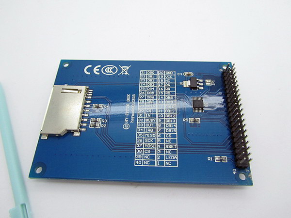