I also have a maple mini clone and I have upgraded to windows 10.
I can set the device into programming code, but how do I get Arduino IDE to program this device via RX and TX?
What settings do I use on the IDE?
All the documentation I have been able to find so far states that you need to use the usb driver – which doesn’t to work on windows.
Raj
I think you may be the first w10 user
Did you install the Windows drivers?
Its possible they dont work on W10 ![]()
Since ftdi gate, I’ve lost faith in usb to serial drivers.
My cp2102 works fine for the moment, but my prolific and ftdi adapters no longer work because of dead drivers.
The ch340s that I bought also work like a charm. I can always use a uno to program the stm32 if I have to.
It assigned a com port and all.
The cable was working fine on a due so not sure what is happening there.
Those micro usb sockets on the blue pill are not strong.
I had to resolder one when it came loose, i suspect it has a dry joint.
also, i recommend you glue the micro usb socket in place by covering it with epoxy or hot glue etc, otherwise sooner or later it will snap off.
having used your board for a bit, I think it would help (for the noob like me) to have a photograph of the particular board in the sticky introduction of the sub-forum. As there are a few flavours of this board coming out, its hard to tell sometimes which board is being discussed. Otherwise well done.
I did try the fastled3.1 library with the stm and it wouldn’t compile ![]()
I know I broke one almost straight away and one I gave to @madias broke as well ![]()
So now I always put hot glue all over the connector
Personally when I design PCB’s I don’t like using micro USB connectors for consumer electronics, as I don’t think they are strong enough.
Mini USB is far more robust but its still possible to break the connector on a Maple mini, if you press down too hard and the usb cable has something under it.
I can see why the Arduino team chose those massive USB connecors for the Uno, especially as they get used in schools.
The BBC (UK) new micro controller board the “Micro:Bit) has a micro usb connector, but I think they are bound to be broken very soon in a school environment.
(LOL)
That would probably be me, I was prone to hacking stuff even at school.
I have 2 computers (mine and my sons)
We are both running WX (windows 10)
I installed the latest build of the drive (10 minutes ago).
I get an assigned comport but I get wierdness.
With one blue pill I get the noise of the usb being plugged in and I get a com port.
But I get this:
Sketch uses 12,316 bytes (10%) of program storage space. Maximum is 122,880 bytes.
Global variables use 2,560 bytes of dynamic memory.
maple_loader v0.1
Resetting to bootloader via DTR pulse
Searching for DFU device [1EAF:0003]…
dfu-util – (C) 2007-2008 by OpenMoko Inc.
Couldn’t find the DFU device: [1EAF:0003] This program is Free Software and has ABSOLUTELY NO WARRANTY
the other blue pill gets no com port in my computer.
On my sons computer he gets no com port just the noise.
this is the code:
// the setup function runs once when you press reset or power the board

void setup() {

// initialize digital pin 13 as an output.

pinMode(13, OUTPUT);

}

// the loop function runs over and over again forever

void loop() {

digitalWrite(13, HIGH);   // turn the LED on (HIGH is the voltage level)

delay(50);              // wait for a second

digitalWrite(13, LOW);    // turn the LED off by making the voltage LOW

delay(50);              // wait for a second
I’ve never seen any generic board with a bootloader, I’ve had generic boards arrive (from eBay vendors) that have the LED flashing, but thats all.
The easiest way to flash the blue pill’s is using a USB to serial adaptor. This is well documented, and I’ve posted youtube videos about it.
Maple mini should come with the bootloader, but you need to load (install) the windows drivers using the Bat file in the drivers\win folder.
I think one other person is using W10 and did get it to work, ie I think the drivers still install even on W10, but this may not apply to all W10 versions.
1. Connect the Boot1 pin to GND (I usually use a 3.3k resistor instead of a direct connection).
2. Connect the usb/serial adapter to TX1, RX1, Vcc (3.3V), and GND on the mini.
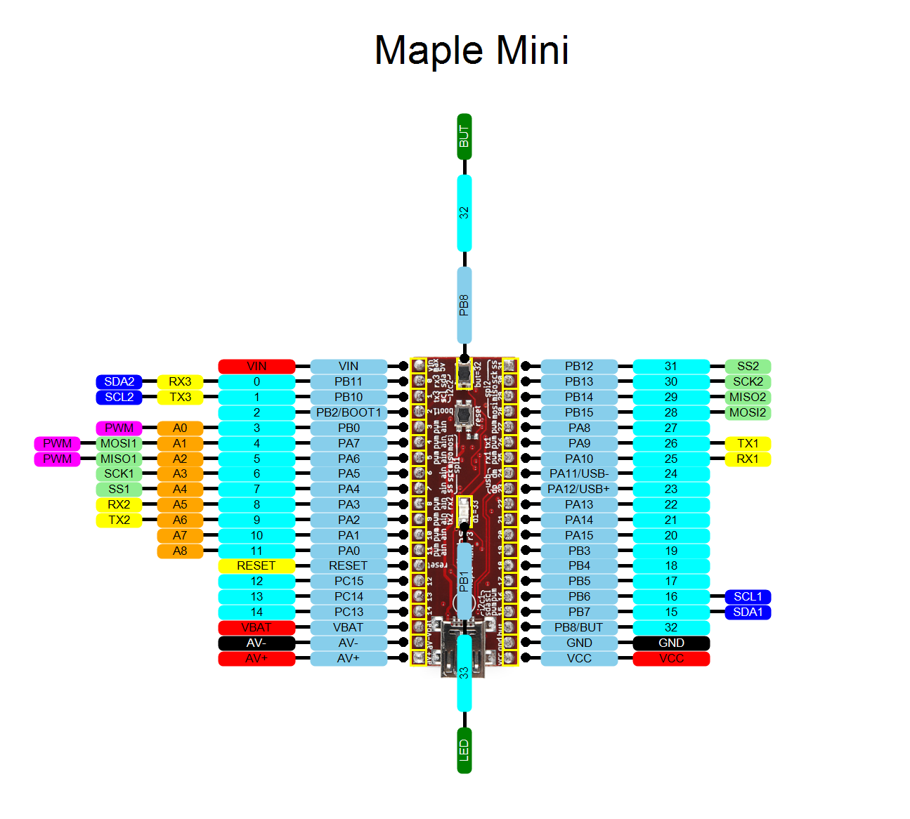
3. In the boards menu, select Generic STM32F103R series, Variant STM32F103RB, 20kb ram, 128Kb flash.
4. Select Upload Method: Serial.
5. Select the correct serial port.
6. Press BUT, then press reset. Release reset first, then release BUT (there should be no blinking leds).
7. Compile and upload.
This replaces the bootloader with your sketch.
Repeat steps 6 and 7 to upload new sketches.
1. Connect the Boot1 pin to GND (I usually use a 3.3k resistor instead of a direct connection).
2. Connect the usb/serial adapter to TX1, RX1, Vcc (3.3V), and GND on the mini.
3. In the boards menu, select Generic STM32F103R series, Variant STM32F103RB, 20kb ram, 128Kb flash.
4. Select Upload Method: Serial.
5. Select the correct serial port.
6. Press BUT, then press reset. Release reset first, then release BUT (there should be no blinking leds).
7. Compile and upload.
This replaces the bootloader with your sketch.
Repeat steps 6 and 7 to upload new sketches.
