I’ll give you some of the many questions i have so far, if you can answer any, that would help a lot XD.
High level:
1) what i want to achieve: sending data via circular dma to an i2c port. there wouldn’t happen to be an example like that available? XD
2) concerning DMA, are there libraries available for that? there doesn’t seem to be a library for it included yet? is there anything available i should know of?
Lower level:
3) Is there anywhere where i can find a nice breakdown of which values in which registers i have to set if i would fully manually would want to setup an I2C port, and send data over it? i’ve been reading the manual & looking at examples & libraries, and i’m slowly piecing it all together, but godd*****, finding just the steps to do this shouldn’t be that hard, should it? And piecing it together from hardwire & libmaple is also a bit tedious, it’s spread over quite a few files >_<.
4) I’ve been reading up on the CCR & TRISE register, which i understand basically control the speed of the I2C bus. I changed the values in the i2c.c file of libmaple to make it go at 600khz (while it’s only meant to go at 400khz), still seemed to work fine, anyone already experimented with what does & doesn’t work?
5) If i initialize the I2C bus via the hardwire library, is it then ready to have the dma controller use it? (i’m wondering a bit about the DMA request part, but i’ve currently mostly focused on just understanding the I2C bus).
6) One of the experiments i did was very simple code: set up the i2c bus in hardwire, and while(1) send some data to it. That seems to completely crash everything? When testing with just doing a finite number of writes, anything above 30 or 31 seems to repeat this. Just wondering what causes this. (and also wondering if i have DMA basically do the same, if it will result in the same issue).
And i have found threads about people complaining about STM’s poor documentation, and i might agree XD. There definitely is room for improvement XD.
High level:
1) what i want to achieve: sending data via circular dma to an i2c port. there wouldn’t happen to be an example like that available? XD
racemaniac wrote:
2) concerning DMA, are there libraries available for that? there doesn’t seem to be a library for it included yet? is there anything available i should know of?
High level:
1) what i want to achieve: sending data via circular dma to an i2c port. there wouldn’t happen to be an example like that available? XD
Basically the codebase we started with was written my LeafLabs, but they gave up supporting it about a year ago, and even before that they’d stopped done any major development work.
Anyway, they started off doing DMA in one way, and then when they looked at the F2 (and F4) versions, the DMA hardware is different than on the F1.
So I think they re-coded the DMA functions in the core to use something they called DMA pipes.
But from what I recall, when people like @victorpv, started to look at DMA for SPI, they found that it was easier to use the old DMA code (not the newer DMA pipes code)
I think that both the older version and the new DMA Pipes code is in the F1 core.
I know this doesn’t help too much, but it may explain why any example DMA code looks a lot different for the F2.
Re: RM0008
It is hard to read, so with the DMA you may be better off looking at the stuff in SPI and cross reference against the manual to see if DMA for I2C works in the similar way.
Oh…And … The other person that did some DMA stuff is @ahull who has done DMA from the ADC for his Pig-O-Scope project.
It may be worth looking at his DMA code to see if it helps
I can’t be much more help, as I’ve only briefly looked at the DMA myself.
I think my next step for understanding the I2C port will be to just look into exactly what the hardwire library does to initialize the port & send data, so i can set up a minimal program for myself that does the same
and for dma i’ll indeed have to look at those projects, they’ll give some good examples on how it works i hope
As a side note, i have to say i love how much knowledge there is on this forum ![]() . Whenever i visit the arduino forum, you drown in the dozens and dozens of posts of people who hardly have a clue what they’re doing XD, and keep asking the same questions that were answered al million times already, or found a new creative way of shooting themselves in the foot XD. And here you see most discussions are pretty technical and pretty much everybody here knows what they’re doing XD.
. Whenever i visit the arduino forum, you drown in the dozens and dozens of posts of people who hardly have a clue what they’re doing XD, and keep asking the same questions that were answered al million times already, or found a new creative way of shooting themselves in the foot XD. And here you see most discussions are pretty technical and pretty much everybody here knows what they’re doing XD.
Lets hope this never gets too popular so it remains like this :p ![]()
![]()
<…> Whenever i visit the arduino forum, you drown in the dozens and dozens of posts of people who hardly have a clue what they’re doing XD, and keep asking the same questions that were answered al million times already, or found a new creative way of shooting themselves in the foot XD. And here you see most discussions are pretty technical and pretty much everybody here knows what they’re doing XD.
Lets hope this never gets too popular so it remains like this :p
Not always finding ready made blocks for what you want to do is part of making stuff XD. it’ll probably annoy the hell out of me for a few more weekends as i struggle trough it, but if i get it to work the way i want it to, it’ll be awesome :p.
For those also wanting to give it a try, see the code below.
For now i bypassed the hardwire library so i have full control of what’s happening ![]() (but did use the i2c classes in libmaple that nicely define all the registers & flags
(but did use the i2c classes in libmaple that nicely define all the registers & flags ![]() ).
).
During experiments sometimes my I2C bus got stuck, i made some improvements to this code before posting it (setting stop condition etc..), but it may still happen. Just powercycle the maple and it’ll work again :p.
To improve: the setup of the I2C can use interrupts to see when the flags get set, not the busy waiting it does now.
It should also keep an eye on the error interrupt of the I2C port so it can respond to errors happening
but it’s a start, and i can start experimenting with this ![]() .
.
Greets
Race
#include <dma_private.h>

#include <include\libmaple\i2c.h>
uint8_t data[] = {13,37};
void setup() {
Serial.begin(115200);
pinMode(32, INPUT);
pinMode(33, OUTPUT);
testDMA();
}
void loop() {
delay(500);
digitalWrite(33, !digitalRead(33));
}
void testDMA()
{
delay(10);
setupDMA();//set up the dma before doing anything with the peripheral
setupI2C();//set up the peripheral
i2c_peripheral_enable(I2C1);//enable the port
i2c_start_condition(I2C1);//set the start condition
uint32_t sr1 = I2C1->regs->SR1;
uint32_t sr2 = I2C1->regs->SR2;
while(!(sr1&I2C_SR1_SB))//wait for the start bit to be set
{
sr1 = I2C1->regs->SR1;
sr2 = I2C1->regs->SR2;
}
i2c_write(I2C1, 96<<1);//write the address of the device you want to contact (shifted 1 to the left)
sr1 = I2C1->regs->SR1;
sr2 = I2C1->regs->SR2;
while(!(sr1&I2C_SR1_ADDR))//wait for the ACK of the device. If no ACK is received, the I2C_SR1_AF bit will be set instead, this code doesn't check for that
{
sr1 = I2C1->regs->SR1;
sr2 = I2C1->regs->SR2;
}
//after the ack a dma request will be sent, and the dma controller will take over
}
void setupI2C()
{
i2c_stop_condition(I2C1);//always good to start with, if the I2C bus ended in an invalid state, setting the stop condition usually resets it
i2c_peripheral_disable(I2C1);//and also disable it to be sure
i2c_init(I2C1);//initialize it
i2c_config_gpios(I2C1);//configure the gpios
I2C1->regs->CR2 = I2C_CR2_DMAEN | 36; //dma enabled, peripheral frequency is 36Mhz
I2C1->regs->CCR = I2C_CCR_FS | 30;
I2C1->regs->TRISE = 11;
}
void setupDMA()
{
dma_tube_config i2cConfig =
{
data //the memory we want to do DMA from
,DMA_SIZE_8BITS //the memory access will be 8 bits
,&(I2C1->regs->DR) //the dma will go towards the data register of the i2c port
,DMA_SIZE_8BITS //the i2c port is 8 bits
,2 // we need to transfer 2 times, so 2 bytes in this case
,DMA_MINC_MODE|DMA_CFG_CIRC //we enable memory increment & circular dma. So after the first transfer it goes to the second byte, after the second transfer it starts over again
,0
,DMA_REQ_SRC_I2C1_TX//the source of the interrupts is the transmit buffer empty interrupt if i2c1
};
dma_init(DMA1);//init DMA controller 1
if(dma_tube_cfg(DMA1, DMA_CH6, &i2cConfig) > 0) //for transmission over I2C1 we need channel 6 (see docs)
dma_set_priority(DMA1, DMA_CH6, DMA_PRIORITY_VERY_HIGH);
dma_enable(DMA1, DMA_CH6);
}
//prints the status of the I2C peripheral
void printStatus(char* position)
{
Serial.println(position);
Serial.println("CR1");
Serial.println(I2C1->regs->CR1);
Serial.println("CR2");
Serial.println(I2C1->regs->CR2);
Serial.println("OAR1");
Serial.println(I2C1->regs->OAR1);
Serial.println("OAR2");
Serial.println(I2C1->regs->OAR2);
Serial.println("DR");
Serial.println(I2C1->regs->DR);
Serial.println("SR1");
Serial.println(I2C1->regs->SR1);
Serial.println("SR2");
Serial.println(I2C1->regs->SR2);
Serial.println("CCR");
Serial.println(I2C1->regs->CCR);
Serial.println("TRISE");
Serial.println(I2C1->regs->TRISE);
}
//prints the status of dma channel 6
void printDmaStatus(char* position)
{
Serial.println(position);
Serial.println("CCR6");
Serial.println(DMA1->regs->CCR6);
Serial.println("CPAR6");
Serial.println(DMA1->regs->CPAR6);
Serial.println("CMAR6");
Serial.println(DMA1->regs->CMAR6);
Serial.println("CNDTR6");
Serial.println(DMA1->regs->CNDTR6);
Serial.println("IFCR");
Serial.println(DMA1->regs->IFCR);
Serial.println("ISR");
Serial.println(DMA1->regs->ISR);;
}
Thanks for posting.
I’m sure this will be really handy .
There is a lot of excellent functionality around DMA and timers in the STM32 that we only normally scratch the surface of using
I do feel i’m going a bit against the direction that arduino is trying to offer you XD. rather than using the library and having an easy program, i’m digging deep and going directly for the hardware :p. I had to change the core so i could intercept the IRQ handlers and exchange them with my own
Atm i’m thinking of doing dma on one i2c port for transferring bigger chunks, and on the other port i want to have very precise control of when i send data, so i can go for i2c with clockstretching
I’m going to see if i can wrap these functionalities in a library somehow ![]() . Would be nice for others, it’ll offer a lot more power than just having hardwire
. Would be nice for others, it’ll offer a lot more power than just having hardwire ![]() .
.
But ISRs should always be kept as short as possible and not include any deliberate delay loops.
If things need a time delay, its best to trigger a timer for that delay period and do the remainimg code in the timer ISR.
But ISRs should always be kept as short as possible and not include any deliberate delay loops.
If things need a time delay, its best to trigger a timer for that delay period and do the remainimg code in the timer ISR.
I’m probably doing something wrong ![]() but I’ve not had time to look into precisely why this happens.
but I’ve not had time to look into precisely why this happens.
doesn’t STM32 have a set of ‘domain’ enable bits in a register? domains being spi/i2c/adc/uarts etc
i was going to ask if the OP if he would insert a ‘RETI’ as a handler whilst he changed registers and change to the real handler afterward.
then again, somewhere i’ve seen snippets that need a register bit to be set or cleared to explicitly re-enable a particular operation or interrupt.
apologies, but the place to look for guidance might be SPL example code as it’s much more visible in its steps regarding hardware? actually that’s probably y i don’t use it ![]()
stephen
btw, for those interested, i also tested how fast i could get the i2c port to work with the dac, and even though it’s made to go at 400khz, it seemed to keep working reliably up to 1.2Mhz ![]() . (haven’t tested it for longer periods, but if it manages to keep running without interruption for a few minutes, that’s pretty reassuring). once i tried to go even faster than that, it failed instantly
. (haven’t tested it for longer periods, but if it manages to keep running without interruption for a few minutes, that’s pretty reassuring). once i tried to go even faster than that, it failed instantly ![]() .
.
and for those wondering how to get it that fast: if you set up the speed of 400khz , the CCR part of I2C_CCR will contain the value 30, setting it to 10 triples its speed (duh :p), and still seemed to work ![]() . anything below 10 just failed ^^
. anything below 10 just failed ^^
I think we all like to push the envelope ![]()
I’m currently running i2c in dma, and let the interrupts of the controllers set a global variable to indicate that the dma communication has finished.
I’m not yet doing work during the dma (it’s still setting up the device), so while i’ve got the dma running, i got a wait loop like this:
while(dmaBusy);
<…>
<…>
any variable can be declared as volatile
it basically tells the compiler that the variable can change without any code appearing to changeit.
In this case, it is code in the ISR that is changing it, and the compiler does not know that the ISR is being called by the hardware.
I think volatile can also be used when dealing with memory mapped peripherals
when should you declare something volatile? i’m now saying global variable, but i think in this context the correct term is just static variable (i’m still getting up to speed with c/c++
i know of all these concepts, but it’s still getting used to them when encountering them
i know of all these concepts, but it’s still getting used to them when encountering them
<…>
This time i ran into this issue: http://www.stm32duino.com/viewtopic.php?f=3&t=407
Didn’t know that using “new” isn’t the best idea XD. (i’m splitting all my functionality nicely into small libraries, so i’m starting to have some classes ![]() ).
).
<…>
This time i ran into this issue: http://www.stm32duino.com/viewtopic.php?f=3&t=407
Didn’t know that using “new” isn’t the best idea XD. (i’m splitting all my functionality nicely into small libraries, so i’m starting to have some classes ![]() ).
).
<…>
I hope i’ll be able to expose what i’m writing as a library
I’ve made a little I2C library that works via DMA & interrupts, making it easy to send i2c data in the background and multitask
<…>
<…>
I hope i’ll be able to expose what i’m writing as a library
I’ve made a little I2C library that works via DMA & interrupts, making it easy to send i2c data in the background and multitask
<…>
<…>
I know, it already exists, i’m also heavily relying on everything already in the framework, but i’m not entirely sure if i’ll be able to change hardwire to work easily with dma, there are some annoying differences between both modes
When i get everything working the way i want to, i can have a look if i can get it closer to the existing libraries, or if i keep it more of a separate lib like it is now
<…>
Thanks for the extra info
<…>
I’m a professional programmer, but it’s the first time delving deep into this low level stuff
<big post>
Ray
I’ll show the logic analyzer output of what i reached so far. It’s code that’s reading the mpu6050 which is outputting 100 dmp samples of 42 bytes per second.
Here is the original result of the program you can find linked on this forum, using I2C at 100khz rate
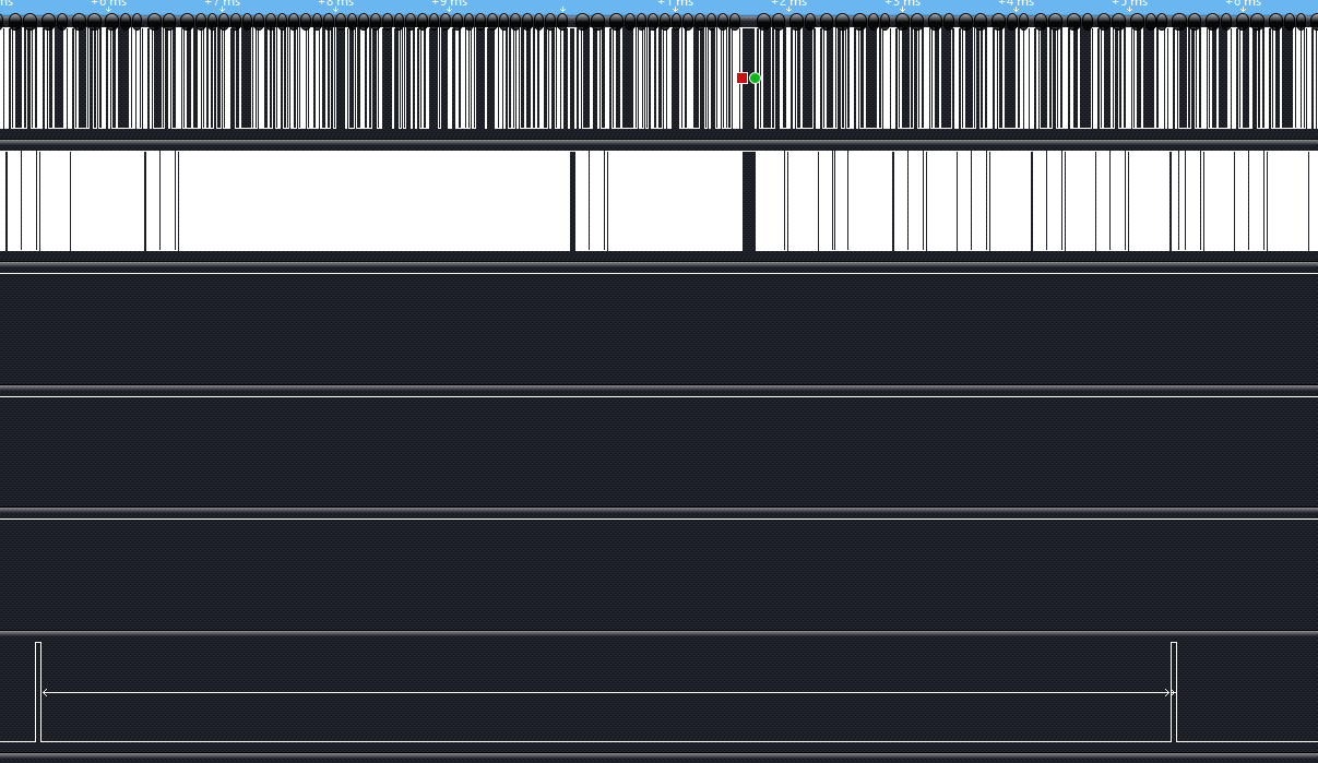
http://users.telenet.be/racemaniac/original.png (also added an url to the image, as it doesn’t seem to load with the img tag on my browser?)
Basically the microcontroller is swamped and can’t keep up at all. it’s reading a bit more states than my eventual program reads, but not that much, it’s also a pretty slow i2c implementation that doesn’t even reach the 100khz completely. (just putting hardwire into this would already improve it
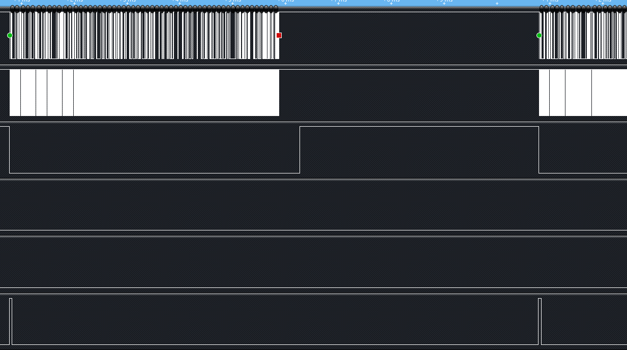
http://users.telenet.be/racemaniac/sync%20dma.png
This is the result with my dma code, but it’s still waiting while sending/receiving data. on channel 2 you see the line pulled low when the cpu is busy, and high when it’s free, it’s busy about 50% of the time since it’s all the time waiting for communication
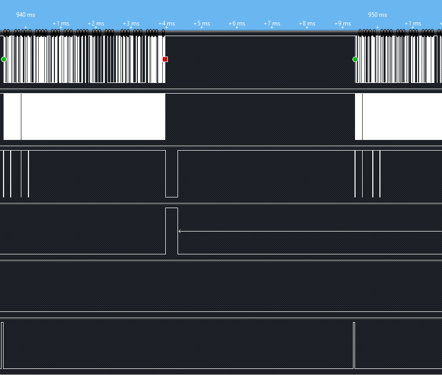
http://users.telenet.be/racemaniac/async%20dma.png
And this is the final result i wanted. Channel 2 again shows when the cpu is busy, but when the dma is active, the cpu no longer has to wait. So rather than being busy 50% of the time, it’s now only busy about 5% of the time (which is doing some complicated math to process the results. transferring the data is negligable). per pulse on channel 5 (interrupt pulse of the MPU when data is available), you’ll see 4 pulses on channel 2 (4 dma requests), and then a bigger block which is the calculations. So only the processing of the data now takes time ![]() .
.
That’s what i wanted to achieve with dma ![]() . and at 100khz it appears to be very stable
. and at 100khz it appears to be very stable ![]() .
.
I abandoned a IMU project using an MPU9150 as the drift caused by offsets in the data was impossible to remove. ( it also did a lot of maths, which took a lot of cpu time, but the main issue was the consumer grade sensor are not accurate enough)
I abandoned a IMU project using an MPU9150 as the drift caused by offsets in the data was impossible to remove. ( it also did a lot of maths, which took a lot of cpu time, but the main issue was the consumer grade sensor are not accurate enough)
last night fixed the last bugs i had with i2c & async dma. Also made a tiny framework for the sending of sound samples via i2c and clockstretching (as you guys adviced, this one is not a class, just a few static variables & some global methods that do what i need, i2c with clock stretching is pretty simple ![]() ), combined both sketches (and made sure interrupt priority was as i needed
), combined both sketches (and made sure interrupt priority was as i needed ![]() , i’m doing the sound samples with a timer interrupt, but is was being hindered by one section of the dma system ). And it’s been running stable all night fetching data from the sensor, and sending a sine wave over the dac at 16khz
, i’m doing the sound samples with a timer interrupt, but is was being hindered by one section of the dma system ). And it’s been running stable all night fetching data from the sensor, and sending a sine wave over the dac at 16khz ![]() .
.
on to the next parts of this project ![]()
Congrats.
Just as a curiosity, you may wish to try the I2C DMA along with the SPI DMA at the same time … The SPI DMA was implemented last year for use with the TFT displays, etc. Performance increases were astounding…
I have one simple DMA projectthat could be used easily, but you could concoct your own.
Ray
OLD STM Port			non-DMA STM Port             STM DMA Port

ILI9341 Test!

Benchmark                Time (microseconds)		Time (microseconds)        Time (microseconds)

Screen fill              1,026,635			              716,291                    174,901

Text                        74,910				            46,087                     65,358

Lines                      702,724			              400,688                    692,868

Horiz/Vert Lines            84,359				            57,074                     23,342

Rectangles (outline)        54,489				            36,604                     16,625

Rectangles (filled)      2,132,392			            1,487,410                    371,832

Circles (filled)           344,984			              220,662                    181,100

Circles (outline)          306,326			              174,199                    302,904

Triangles (outline)        222,948			              127,154                    219,106

Triangles (filled)         715,597			              472,077                    243,512

Rounded rects (outline)    130,131			               78,591                     91,564

Rounded rects (filled)   2,331,405	                  1,615,938                    488,708

Done!
Made a similar framework to my I2C DMA framework, working under interrupts
I’ve now got a neopixel string of 144 leds updating at +180 frames per second via a signal generated via the hardware spi & sent via DMA
I’m now starting to wonder what to do with all this code ![]() . I’ve got some nice lightweight dma frameworks for I2C & SPI, not sure if anyone is interested in them
. I’ve got some nice lightweight dma frameworks for I2C & SPI, not sure if anyone is interested in them ![]() . and will have some frameworks on top of them to address neopixels, an mpu6050 and an MX25L3206 (flash memory chip).
. and will have some frameworks on top of them to address neopixels, an mpu6050 and an MX25L3206 (flash memory chip).
<…>
I’m now starting to wonder what to do with all this code
<…>
I’m now starting to wonder what to do with all this code