is it possible to keep battery still connected and upload the code by USB?
is it possible to keep battery still connected and upload the code by USB?
I’ve used power banks as per the above thread, and also bare lipos with something like this.. to power various projects over the years. The bare bones lipo boards are good for small projects where space is at a premium, but be aware that you will end up powering the STM32 from the protected output, so effectively from the lipo voltage, so take care not to feed +5V back in to the circuit from any USB serial connected device, or you may get a spectacular reaction from the LiPo. A bit of careful thought and a few strategically placed diodes should keep you safe.
Using a USB Power Bank is pretty easy, you can in fact feed the +5V to its charger circuit from the USB port on the Maple Mini (don’t blow up that diode now ![]() ) and hide or remove the input USB port on the power bank. A couple of schottky diodes might be a wise precaution to avoid feeding 5V in to something that expects 5V out.
) and hide or remove the input USB port on the power bank. A couple of schottky diodes might be a wise precaution to avoid feeding 5V in to something that expects 5V out.
You can also feed the maple mini from 3 x AA batteries, or even feed the regulator from something a little higher (up to 9V as I recall, but check that), so long as you take care when plugging in the USB, again try to avoid feeding >5V in to a 5V output, it wont be happy.
What is the project, and how much power do you think it will require?
Would like to use lipo battery to power it.
So I understand that if I connect lipo battery into GND and VIN pins then I can connect USB cable into USB port to program maple?
Then for what purposes is VBat pin?
The BOM is
1xESP8266
1xESP8266 breakout board, modified with on board regulator, which is why the resistor in the middle of the bottom of the board has been removed the LDO regulator is on the reverse of the board. google for details of this mod.
1xLiPo Charger board.
1xCheap LiPo with built in protection (Something like this)
The battery in question was sent in error when I ordered a clone Canon NB-4L battery. the supplier sent replacements, so the one in the picture was essentially free of charge. I’ve soldered the wires directly to the battery, which is perfectly safe, since they connect to the protection board, the pouch cell LiPo connects internally to the same board, so I should be protected from shorting out the battery, over discharging it, over charging and so forth. Furthermore I’ve used the minimum gauge of wire so if I do pass excess current, they should melt/blow before I start a fire, but not so thin that they have any significant resistance.If I was really paranoid, I would add an in-line 1A fuse, or perhaps a MOB or some other protection, but since the battery is pretty small ( <1000mAh) it isn’t particularly hazardous.


To perform the same trick with a Maple Mini, you would need to ensure that you could feed the on board regulator from the Lipo, so a low drop out regulator is essential, also some diode protection so you don’t end up charging the LiPo from the USB +5V by mistake.
They are a little pricey, but they appear to contain a usb charger board, a lipo and a boost board to provide the 9V. Useful for 9V power hogs like multimeters, calculators and other PP3 powered gadgets.
They might not be appropriate for the application being discussed in this thread however.
In which case I wonder what the effective capacity really is, given the regulator is going to waste energy.
In which case I wonder what the effective capacity really is, given the regulator is going to waste energy.
silence.
i asked for how long? 1mSec
i’m not entirely sure i believed him even then.
that led me to kinked wire ignition for a cannon, subsequently testing my survival reflex.
stephen
I suspect it would be cheaper to build your own ![]()
…
that led me to kinked wire ignition for a cannon, subsequently testing my survival reflex.
stephen
I suspect it would be cheaper to build your own ![]()
Re 3D printing
I forget exactly what its called, but there is a community online printing website, which lists local people who have a 3D printer, who will print your design ( for a small fee I presume)
I use OpenSCAD for a lot of my 3D designs, because its a programming language that outputs 3D objects. There is also a similar online system call openJSCad
I then checked this every minute with a wget from my laptop to see how it performed.
..

Sat Feb 27 17:45:12 GMT 2016 ESP8266 is UP

Battery Voltage: 3.496

Sat Feb 27 17:45:13 GMT 2016 ESP8266 is UP

Battery Voltage: 3.496

...

...

Sat Feb 27 22:58:10 GMT 2016 ESP8266 is UP

Battery Voltage: 3.496

Sat Feb 27 22:58:11 GMT 2016 ESP8266 is UP

Battery Voltage: 3.496

Sat Feb 27 22:59:12 GMT 2016 ESP8266 is DOWN

Sat Feb 27 22:59:13 GMT 2016 ESP8266 is DOWN

...
You are an expert in powering things ![]()
Do you know what these are
http://www.aliexpress.com/item/Free-shi … 58b64dbbca
Looks like a little mains transformer plus some regulation.
But its kinda hard to tell from the Aliexpress listings
I also found these, which look interesting for powering standalone boards
http://www.aliexpress.com/item/220v-5v- … e163ea94e2
But I’m not sure if they are any good, apart from being nicely encapsulated
Edit
I also found this review
You are an expert in powering things ![]()
Do you know what these are
You are an expert in powering things ![]()
Do you know what these are
I have several power monitoring projects that run standalone with small colour LCD screens, which I have been running from those cheap 5V USB chargers.
I looked for small switch mode PSUs on eBay and AliExpress, but most of the small ones look decidedly cheap and nasty.
However those encapsulated ones, have the appearance of being a bit better.
I was also looking for a small PCB mains transformer so that I can sense the voltage waveform of mains ( using the STM32). Currently I have to find some old transformer type chargers and remove the rectifiers and any voltage regulation, so I can just get AC.
But small mains transformers seem to be used less and less and are consequentially getting harder to find at reasonable prices.
Maybe you can dissect a wall wart and use one of them.
Michael
I have been taking stuff to pieces to get transformers, but Its not a reliable source.
He also shows you how to make a really low cost (but mildly perilous) set of Christmas tree lights, which illustrates capacitative dropper type PSUs (i.e. no transformer), which are not particularly efficient, and certainly not particularly well isolated, but perfect for some applications.
What sort of load are we talking about? <100mA perhaps? If you are looking for a mains rated transformer, there are loads about, try this search. They are becoming more expensive than comparable cheap switch mode PSUs, since the latter are far more popular these days.
I had considered one of those capacitor based PSUs. I used to see them a lot, but I’ve noticed recently that even small mains powered devices often have a switching PSU instead.
As you know, those capacitor based (transfromerless) PSU’s are not very reliable. A common problem is that the series resistor seems to overheat, because they don’t put a large enough wattage resistor (to save space and cost)
I am not doing this project commercially, but I also heard the EEC now require units in standby to consume less than 1W, which rules out the capacitor based PSU’s as the are very inefficient.
I think I may buy a few of those encapsulated supplies and see if they are any good
There also some western companies (Vicor for exemple, but even ST has some) that produce such modules, but at higher prices.
I think I will buy a few and see if they are any good
Cheers
Roger
They also do this item which looks like a fun little toy if you want a low current adjustable supply with a little more visual appeal than the many LED versions.

You could buy both, and build a 0 to 10V adjustable 1A supply, or pair it with an old laptop wall wart (typically 19V at 4 or 5A), to build yourself a small compact 18V 3A adjustable bench supply.
Im designing at the moment for a home project which needs a 3.3V supply, so I will design the board to fit the supply
BTW. i also have some LNK304 ics , which are non isolating switching, for mains to Low voltage applications, but I have never got around to using them, as they need inductors and fast acting diodes, which i still need to buy
I was also looking for a small PCB mains transformer so that I can sense the voltage waveform of mains ( using the STM32). Currently I have to find some old transformer type chargers and remove the rectifiers and any voltage regulation, so I can just get AC.
Thanks for the link.
It seems a strange device.
I found a datasheet http://p.globalsources.com/IMAGES/PDT/S … 796210.pdf
And then I found this linked from a post on the Arduino.cc forum https://forum.arduino.cc/index.php?acti … ach=142556
It definitely looks like this is a very good way to measure mains voltage and phase, as the datasheet seems to say that for 220V input you use a 200k resistor in series with the primary, as this seems to dissipate around 1/4w in the input series resistor (which isnt too bad),
The output sampling resistor, would be just under 2k, for an input of 220V RMS and output of 3V (peak to peak)
It looks like i can get individual ones from eBay for the same price or cheaper than I can from AliExpress, so I’ll see if I the experiments kitty can scratch together a few dollars so I can give them a try.
Thanks for the link.
The output sampling resistor, would be just under 2k, for an input of 220V RMS and output of 3V (peak to peak)
I made a custom PCB, which uses a Maple mini, and a ILI9341, a nRF905 and also an ESP8266 and it works really well using the Open Energy Monitor library
Actually, at the moment I’m not using the ESP8266, I just added it to the board in case I wanted to log via wifi or possibly run a web server on the ESP8266 to display the data etc, as well as the analogue electronics needed to level shift the ac waveforms from current clamp and the mains voltage sense transformer.
The nRF905 is used to transmit the data to multiple identical boards, but the receiver boards don’t have the analog input components fitted, they just have the maple mini, nRF905 and ILI9341, and act as remote displays, mirroring what is being displayed by the monitor board – which is actually connected to the current clamp and to the mains voltage and phase sensing transformer
(well, the phase is relative… its just the difference in phase between the voltage and the current thats important, as it makes it possible to determine power flow direction, assuming the load (the house) is inductive)
I did the board in Eagle, though I am slowly moving to KiCad for new designs.
The first batch of PCBs had a few screw ups, because I rushed to put in some protection zeners on the current clamp input, and ended up deleteing one of the input tracks.
So I had to strap the boards to fix this.
I also missed a pull down on the ESP8266.
Anyway, its a long story, so I will start another thread, later, so this thread can go back to its original purpose
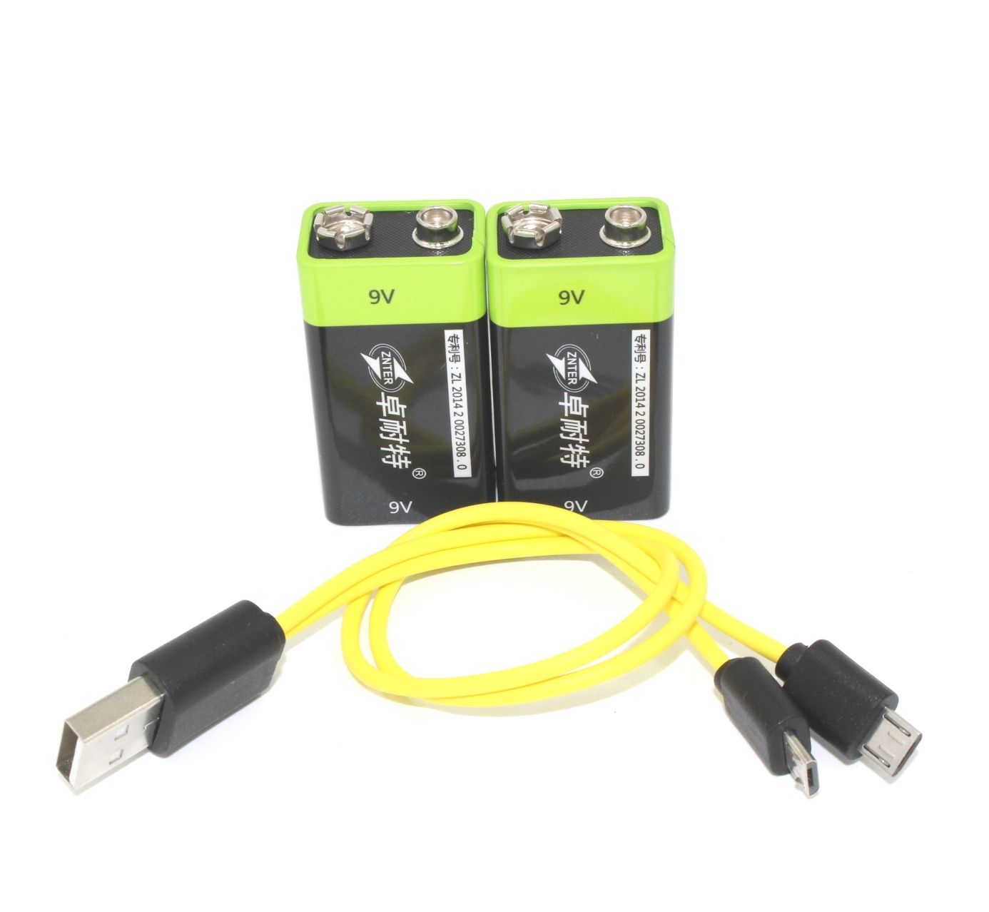
I bought 5 of these to power the gprs modules I got. I was planning to power them direct from the Lipo connections but found the a6 had a voltage regulator already. the sim800 can be powered from the lipo.
It has a 5v output for your maple mini you have the conversion losses from 3.7v —> 5v then back to 3.3v again. Its a cheep regulated 5v supply for 75p. You could power the vcc from the +ve of the lipo via a diode you would need to check the voltage specs of the peripherals though.
The batteries I got were a disaster only 280maH not the reported 6000mAh. to be honest I knew they were fakes I was hoping for 500mA+ though. They only weighed the same as a AA battery which really gives the game away.
http://www.ebay.co.uk/itm/10PCS-5V-Micr … SwoBtW355v
Which are more efficient, as they have a battery output, which is not converted to 5V, and also provides discharge protection.
In quantities of 10, they are only 32p each, and you can probably get cheap single cell battery holders for LIPO cells
In quantities of 10, they are only 32p each, and you can probably get cheap single cell battery holders for LIPO cells
There are quite a number of variations on that theme….
http://www.ebay.co.uk/itm/Mobile-Power- … SwzJ5XVh03
…for example. Which LiPo charger chip do the ones you purchaed use?
