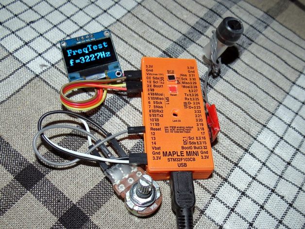
As I always have a million tools and other things lying on my desk, there is always a danger of inadvertently shorting some of the pins on the Arduino Nano, Pro Mini (or now the Maple Mini) module when wiring it up to test some new project. So a few weeks ago I made the Nano Pin Protector which keeps the pins horizontally (instead of downwards) and well protected from being shorted by accident, and also has the pins clearly labeled.
So now working more with the Maple Mini, I thought that having the same kind of pin protector for it would be useful, too. So I adapted the shell and the labels and put the Maple Mini Pin Protector on Thingiverse today. As I often need more GND and VCC connections, I have added a version with additional 3.3V and GND pins at the top. This also gives me a GND pin right besides the Vin pin, and make the I2C-2 pinout symmetrical to the IC2-1 regarding the power lines.
Anyway, maybe there are some readers of this forum that might also be interested in this little project…
—> http://www.stm32duino.com/viewtopic.php?f=3&t=22
Honestly: This is really a superb nice project and a really useful gadget. Shame on my, that I don’t own a 3d printer yet.
* we need a like button here Roger! *
-rick
I have a MendelMax, so I will try printing your files.
BTW. How did you put the text onto the top of the 3D print?
For anyone without a 3D printer, there are companies like Shapeways that will print anything from the 3D files.
I’m not sure of costs, as I have never used that sort of service, but perhaps there are now some cheaper / Chinese alternatives to Shapeways.
The other thing that people may not realise, is that there are programming languages to create 3D objects, which I think is what @enif used.
So you can all go off and modify the design, just by changing the program !
Have you by any chance a protector that works with vertical headers?
For anyone looking for where to print it, www.makexyz.com and 3dhubs.com help you find local 3d printing services.
There are probably more listings like those 2.
@madias: If you knew how much black smoke I already produced, you’d make me a honorary member of that club… ![]()
@Roger: The text with the pin labels is simply a sticker. For each version of the protector shell, besides the STL object file there is also a PDF file that contains the corresponding label in various colors that you can print, cut out the desired color and stick it on the shell. I use “endless” 6×4″ self adhesive sticker paper (shown on some of the photos), but anything else will do as well. Just make sure to turn off any type of scaling before printing. If you need different color or layout, there is also the PostScript source file included.
@victor_pv: No, this type of shell is only for horizontal pins. Having the pins arranged horizontally by use of right angle pin headers was really the key idea to allow me working with the uC on a flat table, having pins, LEDs and buttons always accessible. And also, the horizontal pins enlarge the top surface, giving space for more readable pin labels. However, as Roger explained, the maplemini.scad file is the OpenScad source, which you can modify as you like. But on Thingiverse there are also other Nano shells that all use vertical pins, so maybe you can start from there to make a Maple Mini shell for vertical pins.
I will have a go at 3D printing one at the weekend; at the moment that PC that was normally hooked up to the 3D printer got repurposed to run my desktop CNC mill, so I’ve just had to install Cura onto an old laptop running Lubuntu, so hopefully that should be able to drive the printer as well as Cura on Windows XP. (I copied the settings across to the laptop, so hopefully that should be OK).
I also don’t have any right angle pin headers, so I’ve ordered some from eBay. As its not possible for me to but them locally.
But in a few weeks I should be able to build one, as they seem to be an excellent idea.
I should imagine they would be useful in a teaching / school environment, probably less prone to damage than even a Uno etc
Well.. I printed the pin protector, and I love the way the button pop-outs work (amazing)
However, I think the dimensional accuracy on my printer needs to be re-calibrarted, as the Baite Maple mini was a very tight fit and I was stupid enough to press down hard, and I managed to detach the fixing pads on the USB connector.
This is totally my stupidity, and the board still works fine after I glued the USB connector back down.
So I”ll need to re-calibrate my printer, as its printing a bit small I think.
I took a quick look at the SCAD file, but I couldn’t easily see what the overall external length of the top is supposed to be.
Mine measured to 61.72mm, but I suspect that it should perhaps be 62mm long, or perhaps a little longer.
Or possibly my flow rate is a bit high, so its laying down to much plastic.
Actually, its been the first time I’ve used the printer in a few months, and I was bit bit surprised it worked straight way.
The only slight issue that I could see with the print, was that it looks like one of the corners of the bottom, had a bit of an issue with the PLA not sticking. I’ll probably need to check the bed height calibration as well, and also scrub the kapton tape with some green kitchen scourer as I find that helps with the adhesion.
Can you do me a favor, and take some photo’s that show how the USB connect interacts with the bottom section, as I think this is how I broke my connector. The lug looks a bit big to me, or perhaps I’m somehow assembling it wrong
Anyway, thanks again for sharing this, as I do think it will prove useful.
I know that I usually make the dimensions of holes and cavities rather tight, I prefer to have to take a bit of material away rather than have thing too loose. For me, it always worked well, but I always had to clean the edges of the Maple Mini PCB with an knife, since there were some “brims”. But if its too tight, just increase the L0 and W values.
Here a photo showing the USB connector on the lower shell which I just uploaded to the thingiverse page (where you can also display it with better resolution):
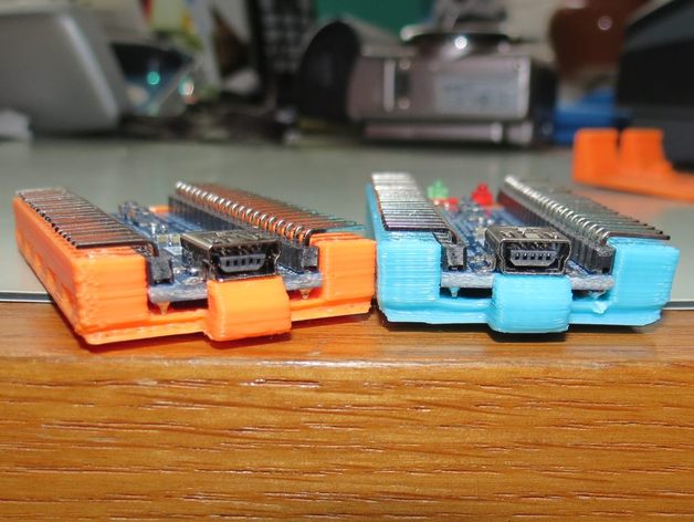
Is this the type of photo you were looking for? If not, just let me know what exatly you need.
I think there is something missing from the SCAD file and one of the STL’s
Your boards seem to be sitting on rails, but the rails don’t seem to be in the SCAD file that is on Thingiverse
Ah.
Sorry.
I see what. Those are the ends of the pins that the board is resting on, its just that they are shiny and refect the colour of the print in both cases and look a bit like printed rails.
My mistake was to use a board without an pins soldered into it, I presumed it was supposed to rest on the raised sections either side of that central channel, but as I don’t have any 90 deg pins, I tried inserting a board without any pins on at all, hence pushing it down, the USB connector bumps into the lug at the end.
I will need for my 90 deg pins to arrive again before I can try it again, but I also have some issue with the top bowing. But I’m sure its my printer calibration, (extruding too much plastic).
Also I realised at the end of the print, that I had the fill density set to 5% from the last thing I printed, and I think its possibly made the top of bit more flexible than if It was set at a more normal value like 40 or 50%.
I printed in PLA, What did you print in ? (I have ABS as well, I’d need to change the bed glass to print ABS, as I find that its best to print straight onto glass for ABS, but for PLA I print onto slighly roughed up Kapton tape)
BTW when assembling the lower and upper shells, make sure to first place the USB end as it should be and then “click-in” the button end, as the USB end is more fragile and the button end has a skewed inside for easier sliding.
No worries.
I will try to make a short video of how my print turned out, in PLA with fill set at 5%.
The bottom part is fine, but I think the top is a bit too flexible.
I prefer ABS, but I have a lot of spare PLA, as I was accidentally sent PLA when I ordered ABS. I got free ABS replacements, but I ended up with more PLA than I need, so I often use it for “test” prints.
Anyway, thanks again for doing the design.


