I need a quick advise:
I’ve build in the maple mini into a project and need a breakout USB connector. My idea was to use:
D23 USB D+ and D24 USB D-
I’m pretty sure that I tested this successfully some weeks ago (using an older bootloader?), now it wont work (tried it even on another maple mini and different USB cables and tested the connections out with my continuity tester)
Ok, one possibility is to “hijack” the pins of the original usb connector, but this is more or less botch.
I think, I have missed something and/or maybe it’s better to use a “generic bootloader” for using D23/24 “native”? But the only difference between the onboard connector and the D23/24 pins are a 22Ohm resistor on each rail…
Edit: Ok, I looked at many STM32/USB connection schematics: The two 22R seem to be important…will try it at home.
And if you are trying to connect the USB to the pins directly, besides the 22ohms, you need a 1.5k pull up resistor on D- to VBUS.
I know, but it must be given trough the schematic (R10):
Maybe the mini clone isn’t 1:1?
I’m not sure where you are connecting the external USB.
Can you scribble a circuit and photo it and post it ?
I think you are saying that you are connecting pin 24 and pin 23 to another USB connector (via 22 ohm resistors), but that his does not work ?
(looking at the schematic, I think that should work, as all you are doing is replacing the part of the circuit which is resistors R6 and R7 and the USB connector.
Roger:
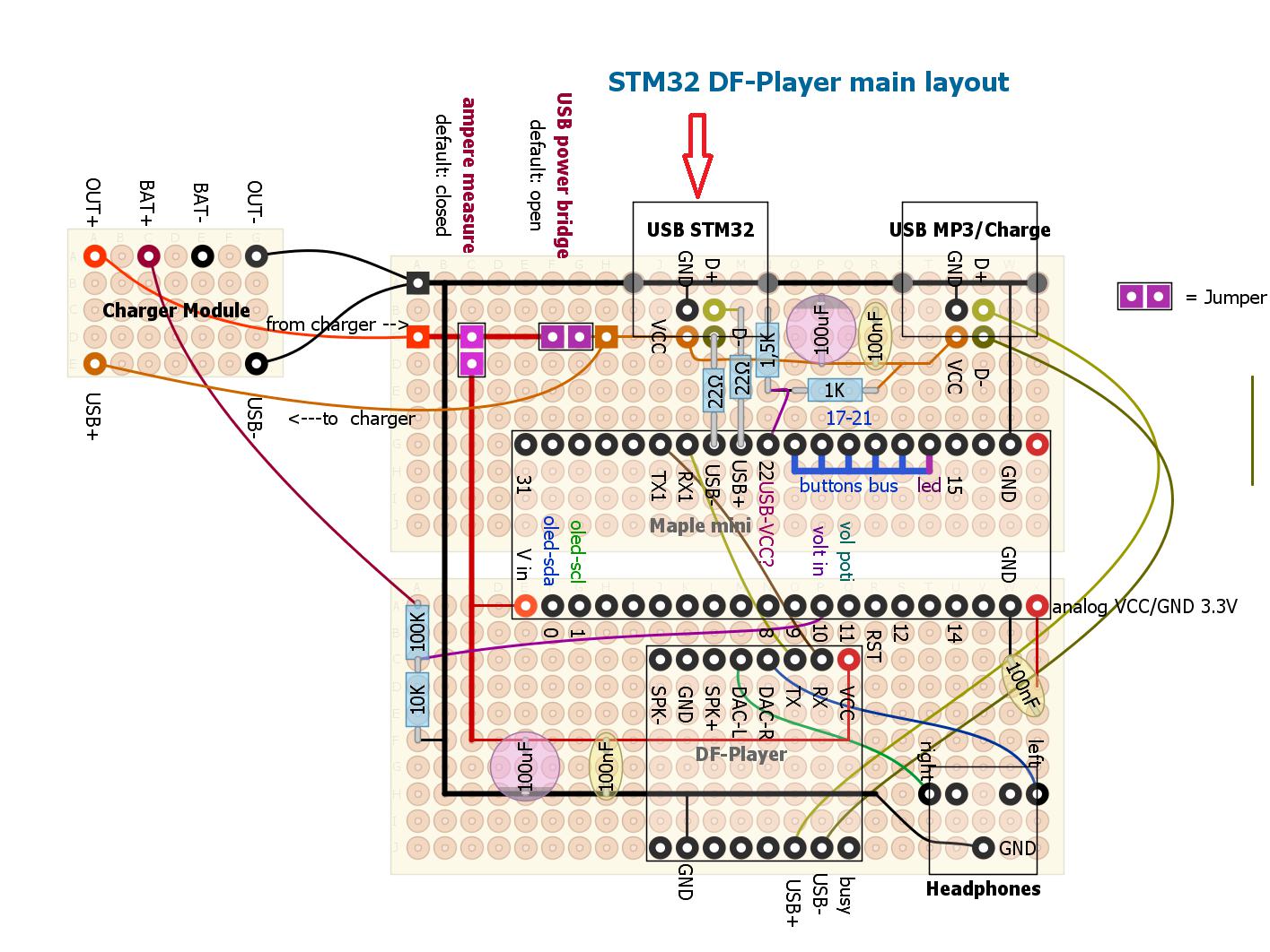
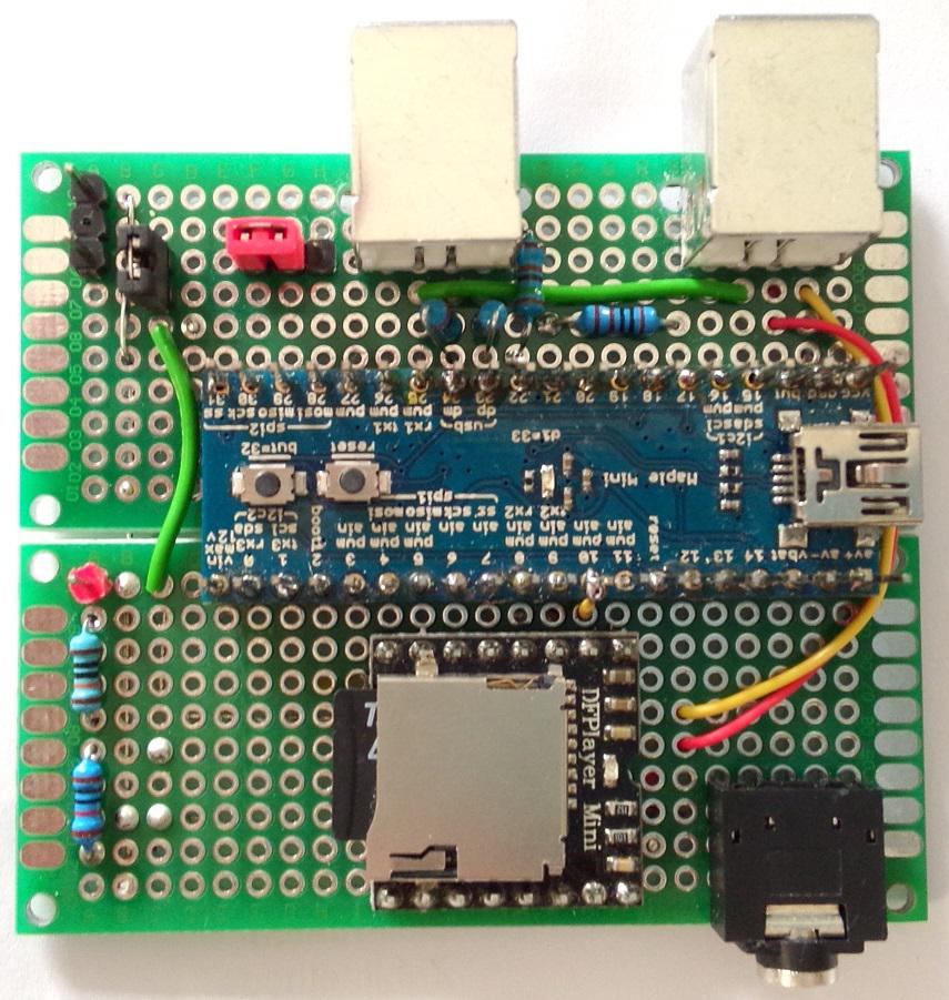
I’ve added a schematic and a photo, connection is easy:
[USB connector]——–[maple mini]
VCC <————————-> Vin
GND <————————-> GND
D+ <———-[22R]———> D23
D- <———-[22R]———-> D24
As you can see on the schematic, there is a second USB connector for the DF-player. This works frictionless, so I can exclude a problem with the cable.
I also triple checked all connections (even if they are reversed …) and resistor values:
So I measure [22-29Ohm] from:
[build-in-USB]——physical Pin——–[ext. USB]
D+ <———-[22R]—-D23—-[22R]——> D+
D- <———-[22R]—-D24—-[22R]——> D-
So I’m really clueless. Maybe the problem is that I power the mini from Vin?
additional declaration for schematic below:
D22 is only a indicator if USB power is on (through a simple voltage divider)
D10 measuring the “real” battery status.
All test are with the minimum needed parts online (so no ext battery…)
Edit: Maybe it’s even a smarter idea to connect the 5V direct to “USB_5V” to get the whole mechanism (transistors,…) working for the bootloader mode. (or use the “generic bootloader”)
Edit2: Solved! Put a small wire from the onboard 5v USB pad to Vin. Little bit ugly, but it worked (problem is, that the mini is already soldered, so I haven’t got access to the “bigger” solder pads on the backside).
Looking at the full schematic for the Maple mini, the USB_5V is used by the reset circuit (like you said).
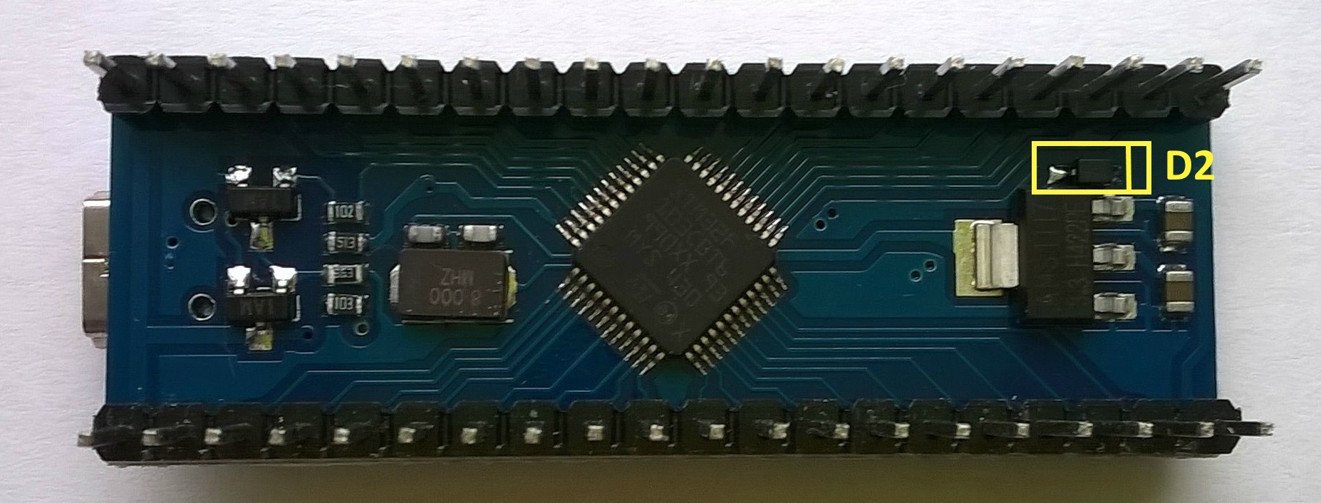
One other option is to short out diode D2, but I don’t know where it is.
Edit.
I tried to find the diode on by board and I think its next to the regulator on the back of the board, but I think my board is not the same as yours.
In the Eagle BRD file the diode D2 is supposed to be near the middle of the board but there doesn’t appear to be a diode in that location on my board.
So I Baite may have laid out the board a bit differently.
Unfortunately, I totally messed up my wooden front panel with the very last(!) acryl paint finish. Hundreds of crackles in all paint-layers so I have to build it again (now with acrylic glass as material) and I’m under pressure of time….
@Vassilis: This seems like the BAITE on (I know “D2” really well -> from the burned smell
But I think the whole story is a “nice to know” for any next project with seperate USB connection for everyone
And know comes the punchline:
I wrote in the first posting something about “I tried it out weeks ago and it worked!”. Now I know why:
The maple-mini with which I tried it, was the one with the “burned diode” so there was no diode function anymore, just like a plain jumper….and this is the reason why it worked!
Very funny. So you need to burn out the diode to make it work, I hope @ahull or Rick, or Victor (I forget how many people have burnt their diodes)
read this ![]()
BTW. Thanks for sharing your experience with this. I was considering making a Maple mini breakout board PCB, but the disconnect circuit not being powered is a bit of an issue.
I did initially think that the 2 transistor disconnect circuit could be replicated on the PCB (though its a duplication), however the DISC line PB9 is not broken out onto the pin headers either.
So… It looks like the only solutions are to short out D2 or put a wire from USB 5V to the disconnect circuit like you have done.
It would be possible to just put a 1.5k resistor from D+ to 5V, and use a version of the generic bootloader that doesn’t use PB9.
In which case, you would need to select the Generic STM32F103CB board, and use stm32duino uploader, as the reset code in the core is different from when its compiled for Maple mini
I wonder if I can use cut USB cable and solder it into Mini to make permanent connection to program it?
I need to close MCU in my project but from time to time I will programming it, don’t want then take enclosure apart.

