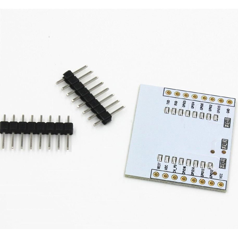
This is the thing I’m talking about.
The ESP-12e modules were pretty cheap, and the adapters came in at £0.49 each, shipped. Not bad I thought.
When the adapters arrived they came complete with… a free ESP-12 …
I checked my original order… yes, I had only ordered the board, and yes they only cost £0.49… so that left me with a problem… I now had three ESP-12e modules with no board (having married up the ESP-12s with the boards they came with).
Now what to do… I ordered another three adapter boards from the generous supplier of course. Now I don’t know if that makes me a bad person ![]() but if I get another three free ESP-12 modules I will reveal the supplier and you can try for yourselves. Now I could of course have gone back to the supplier and point out their mistake… so the question is… what would the rest of you have done in the circumstances…
but if I get another three free ESP-12 modules I will reveal the supplier and you can try for yourselves. Now I could of course have gone back to the supplier and point out their mistake… so the question is… what would the rest of you have done in the circumstances…
You are of course under no obligation to answer, and/or call me out for the thieving cad that I am. ![]()
Lucky guy !
Maybe you should share the link of the seller …
Personally, I added 2mm pins on all my modules, and I’ve made a small proto-programmer with female header, so I’m switching modules to upload sketches.
I did the same with real PCBs that I have designed.
Lucky guy !
Maybe you should share the link of the seller …
Personally, I added 2mm pins on all my modules, and I’ve made a small proto-programmer with female header, so I’m switching modules to upload sketches.
I did the same with real PCBs that I have designed.
Now I don’t know if that makes me a bad person
You are of course under no obligation to answer, and/or call me out for the thieving cad that I am. ![]()
So I just put the breakout boards in my component sock boxes, just in case they come in handy for something else.
The solution (after much head scratching) was a 10k pull down on the TxD pin. It seems the ESP doesn’t like 3v6 input voltages if you are running it from a 3v3 regulator. Well at least this time, no smoke. ![]()
<…>
The solution (after much head scratching) was a 10k pull down on the TxD pin. It seems the ESP doesn’t like 3v6 input voltages if you are running it from a 3v3 regulator. Well at least this time, no smoke.
Therefore 2 x 0.7V drop, 5V – 1.4V = 3.6V …
istr >300mA or am i thinking nrf24l01’s?
you got the -12E’s pretty cheaply, but have you tried finding an adapter plate for the -12E device?
millions listing as suitable for 12/12E, but product shown is only for the -12.
my feedback on some extended base plates i got was ‘excellent for the 0.9 dev kit’. definitely positive feedback ![]()
the 1.0 isn’t wide enough.
the 0.9 exposes 4 holes each side if spanning a pair of ‘supply rails’ bread board
the 1.0 exposes a single line of holes each side when used on bread board, doesn’t make
across the double psu rails, it would if it was a single ‘supply rails’ block
what’s worse is trying to work out the search strings!
<edit>read last post first, so the tiny 3 pin smd is a double diode?
</edit>
stephen
or if picture doesn’t work as in
http://www.stm32duino.com/posting.php?m … 756#pr8431
stephen
But, then, if I remember, the 3pins SMT on the back is simply an AMS1117 3.3V regulator.
<…>
The solution (after much head scratching) was a 10k pull down on the TxD pin. It seems the ESP doesn’t like 3v6 input voltages if you are running it from a 3v3 regulator. Well at least this time, no smoke.
Also, most USB/Serial adapters do no provide enough mAh for the ESP8266… you really need to power an ESP8266 with its own 3.3V supply
Also, most USB/Serial adapters do no provide enough mAh for the ESP8266… you really need to power an ESP8266 with its own 3.3V supply
Therefore 2 x 0.7V drop, 5V – 1.4V = 3.6V …
Therefore 2 x 0.7V drop, 5V – 1.4V = 3.6V …
Do I saw the 1/2 diode length wise or width wise?
I think my 10K resistor is the lowest cost option, and since this is a Cheapskates Incorporated Production, the 10K resistor wins.
Do I saw the 1/2 diode length wise or width wise?
I think my 10K resistor is the lowest cost option, and since this is a Cheapskates Incorporated Production, the 10K resistor wins.
Do I saw the 1/2 diode length wise or width wise?
I think my 10K resistor is the lowest cost option, and since this is a Cheapskates Incorporated Production, the 10K resistor wins.
The quality of the boards is low (obviously), with some hand soldering on the USB connector for example, where they have only bothered to solder one of the retaining lugs. …
The quality of the boards is low (obviously), with some hand soldering on the USB connector for example, where they have only bothered to solder one of the retaining lugs. …
A perfect example of the pressures and issues on a production line that causes chaos: https://www.youtube.com/watch?v=HnbNcQlzV-4
Two silicon + one Schottky diode in series to get closer to 3.3? Geesh, what did that board seller save? $0.10?
I’m thinking single layer board, no leds, smd usb socket, 12mhz resonator to replace the crystal.. don’t solder on the right angled header (or indeed include one at all). Replace the jumper with a solder bridge on the board to select 5V/3V replace the two diodes with a resistor voltage divider. Use a bare die chip in an epoxy blob…
<…>
12mhz resonator to replace the crystal..
…
Thinking out loud on an empty stomach … so this could be a crap idea:
For full-duplex use, I wonder if “auto selection” could be utilized; that is, the unit starts at 3.3V but converts to 5.0V on Send if it gets a 5.0V on Receive. This is obviously a bit problematic in simplex mode, but perhaps could be overcome if the Receive line was tied to the Send line for simplex.
Ray
An interesting idea, but I suspect it would be a little difficult to implement, since you don’t know ahead of time what the receiving end expects.
Furthermore there is a risk that your device will misread the incoming data peak voltage (due to surges, software glitches or whatever) and select the wrong reply voltage, thus cooking the other device….


