So, I did a modification to the files:
Arduino_STM32\STM32F1\variants\generic_stm32f103c\board.cpp
and
Arduino_STM32\STM32F1\variants\generic_stm32f103c\board\board.h
These files are only for stm32f103c based boards. Different STM32 boards may have more or less pins number than the pins number are assigned in those two files.
This sketch turns ON-OFF the LED is connected to pin 33 (PB1 pin) every 0.5 seconds.
/*

Blink LED

*/
#define LED 33 //The LED is connected to PB1 pin.
void setup() {
pinMode(LED, OUTPUT); // initialize digital pin 33 as an output.
}
void loop() {
digitalWrite(LED, HIGH); // turn the LED on (HIGH is the voltage level)
delay(500); // wait for a second
digitalWrite(LED, LOW); // turn the LED off by making the voltage LOW
delay(500); // wait for a second
}
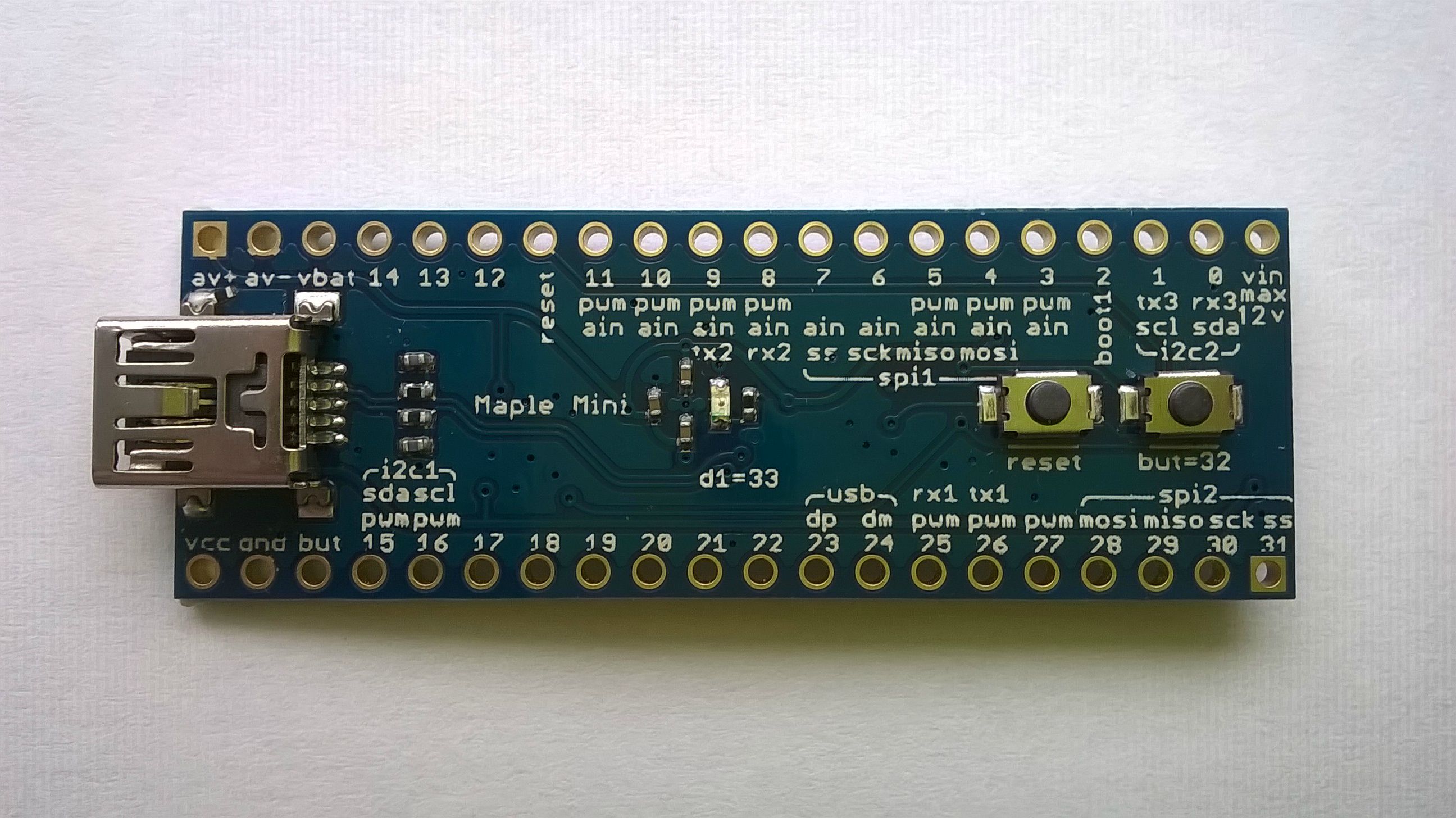
I use maple-mini board like that one
If you connect a LED for example on pin 22 of that board and try to turn it on,
/*

Blink LED

*/
#define LED 22
void setup() {
pinMode(LED, OUTPUT);
}
void loop() {
digitalWrite(LED, HIGH); // turn the LED on (HIGH is the voltage level)
delay(500); // wait for a second
digitalWrite(LED, LOW); // turn the LED off by making the voltage LOW
delay(500); // wait for a second
}
Arduino_STM32\STM32F1\variants\generic_stm32f103c\board.cpp
and
Arduino_STM32\STM32F1\variants\generic_stm32f103c\board\board.h
Arduino_STM32\STM32F1\variants\generic_stm32f103c\board.cpp
and
Arduino_STM32\STM32F1\variants\generic_stm32f103c\board\board.h
@RogerClark, I ran into this too. However, I didn’t modify the board. I added the ST-Link and BMP upload methods to boards.txt for the maple mini entry.
-rick
Compiler start address: 0x8002000 instead of 0x8000000
Not very good in case of using ST-link.
That way not only the pin numbers, but also the USB enumeration, reserved pins, etc all will work as expected in a maple mini.
Rick, perhaps you can send a pull to Roger with those changes? I would guess more people may be interested in using the whole 128Kb, as Vassilis is.
https://github.com/rogerclarkmelbourne/ … ader_20.ld
Make a copy of that file, with whichever name you want. Then edit this line:
rom (rx) : ORIGIN = 0x08002000, LENGTH = 120K
Victor, I will try the changes you suggested.
<…>
I think all boards (maple mini or generic) must have the same pin map for pin compatibility.
It is very important if we want all sketches and libraries to run on all boards without any modification.
Vasillis has just contacted me about this.
(1): PIN MAP layout for Generic vs Maple boards
Initially we used the Maple mini variant for the Generic STM32F103C8 and F103CB boards, but people complained that the PIN MAP layout didnt make any sense.
Which was correct, it doesn’t make any sense at all for boards with the Port / Pin names on the silkscreen.
So I took the Maple mini variant and made the generic STM32F103C variant, and re-ordered the PIN MAP and changed the enum that defines the Port / Pin numbers e.g. PA0 – PC14 etc
I cant see any issues with this.
2. Upload methods and Linker Scripts
This has been a problem for a while. I recall looking at this several months ago.
The problem is that the Arduino Menu’s don’t cascade. i.e they are not interrelated.
The work around was to use the linker script for the top spec board, with any upload methods that need to override the linker script for the default condition.
I recall the linker script for the F103Z -> stm32duino bootloader had to be based on F103ZET linker script
I did investigate if it was possible to dynamically override the MEMORY block information in the linker script, in the link line command.
However basically the GCC linker doesn’t support this (Well its a grey area but it doesn’t seem to work, and from the stuff I’ve read, its a know issue that GCC don’t seem in a hurry to fix)
It looks like this is really only an issue for the Bootloader uploads. On the Generic boards, I default to using the linker script that gives all ram and all flash to the sketch
But the bootloader upload needs to have 8k less flash
Things start to get quite convoluted, but it may be possible to do file name concatenation of linker scripts in platform.txt, but I’d need to do this for all linker scripts ![]()
i.e have the first part of the script name as the variant e,g. F103ZE and the second part as the bootloader / non bootloader
so
linker_f103ze_full.ld
linker_f103ze_bootloader.ld
Anyway, This may be possible, but its not a 5 min job to change it all
Which was correct, it doesn’t make any sense at all for boards with the Port / Pin names on the silkscreen.
So I took the Maple mini variant and made the generic STM32F103C variant, and re-ordered the PIN MAP and changed the enum that defines the Port / Pin numbers e.g. PA0 – PC14 etc

