The slave cards already use SPI_2 to communicate with some peripheral devices, and the master card uses SPI_2 to communicate with an Ethernet and SD card.
The port is completed except for the interboard communications which is always from the master to one or more slaves.
Does anyone know whether the I2C library for STM32F1 will include a slave mode any time soon or does anyone have a suggestion for an alternative?
Thanks in advance..
You may use 9bit transfer, where the 9th bit set “1” will indicate it is the slave’s address (you may address 256 slaves then).
I didn’t realise I could join several Slave Tx and Rx together and then reversed to the master. This gives me the benefit of looking exactly like I2C as far as my project is concerned. It also saves one Usart per MCU.
Do I need to condition the Rx Tx lines in this case Maple mini clone) or can I simply connect them together.
Each MCU in this setup can therefore read every transmission and confirm its own message ( like Old Ethernet looking for a collision).
I like it!
Each MCU in this setup can therefore read every transmission and confirm its own message ( like Old Ethernet looking for a collision).
I like it!
Thanks
Roger
What you trying to do seems to be what ST call Multiprocessor communication as explained at paragraph 27.3.6 in the F103 Reference Manual (RM0008).
I have never tried that but just wanted to let you know that is is documented by ST.
Thanks
Roger
What you trying to do seems to be what ST call Multiprocessor communication as explained at paragraph 27.3.6 in the F103 Reference Manual (RM0008).
I have never tried that but just wanted to let you know that is is documented by ST.
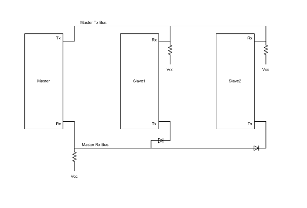
For the slave transmit, I used a small diode at the transmit pin before joining the master receive bus.
To test, I’ve had a small program send a string every two seconds for the past 24 hours, and have each slave acknowledge that they received it. To avoid collisions on the bus I used 100ms increments of delay on each slave (first slave 100ms, second slave 200ms, third slave 300ms) before sending the ack.
The basic circuit is shown below. I now need to write a simple protocol for my needs. My intention is to use one byte address, two bytes message length, the message, and a CRC. I intend have every single address transmission be acknowledged. Every broadcast will not be acknowledged. In this way it is a simple matter to mediate who has control of the bus.
Just to be clear, I am using a TX/RX pair of pins for this (because I cannot get the I2C slave to work). In my test, I used TX1/RX1 on both the teensy and the maple mini clones as it allowed me to use the USB serial monitor to see what was going on.
- cct.png (4.68 KiB) Viewed 800 times
Just to be clear, I am using a TX/RX pair of pins for this (because I cannot get the I2C slave to work).
My day job involves communications between industrial devices. What you are describing is Modbus/RTU, probably using function code 03 or 04. The protocol is serial, allows up to 247 device addresses and has a crc at the end. See SimplyModbus.ca for information on the protocol.
Here is a very nice implementation of modbus : http://libmodbus.org/
you can also check the arduino implementation of libmodbus here : http://libmodbus.org/2011/libmodbus-for-arduino-almost/ ( I have used this implementation many times with AVRs)
Thanks for posting those modbus libs links.
I wrote a minimal modbus implementation with just a few functions e.g. writeRegister writeCoil etc, and it was very simple.
The only difficult bit is the custom CRC and there was example code on the web
In 8051/AVR world the lookup table method is better and faster but requires some code memory more (512 bytes for tables), in ARM world the speed is not an issue and the computational method is more elegant.
Here is my code for lookup table method (using the PROGMEM directive of gcc-avr for storing tables in FLASH)
uint8_t CRCHi[]  PROGMEM = {

0x00, 0xC1, 0x81, 0x40, 0x01, 0xC0, 0x80, 0x41, 0x01, 0xC0, 0x80, 0x41, 0x00, 0xC1, 0x81,

0x40, 0x01, 0xC0, 0x80, 0x41, 0x00, 0xC1, 0x81, 0x40, 0x00, 0xC1, 0x81, 0x40, 0x01, 0xC0,

0x80, 0x41, 0x01, 0xC0, 0x80, 0x41, 0x00, 0xC1, 0x81, 0x40, 0x00, 0xC1, 0x81, 0x40, 0x01,

0xC0, 0x80, 0x41, 0x00, 0xC1, 0x81, 0x40, 0x01, 0xC0, 0x80, 0x41, 0x01, 0xC0, 0x80, 0x41,

0x00, 0xC1, 0x81, 0x40, 0x01, 0xC0, 0x80, 0x41, 0x00, 0xC1, 0x81, 0x40, 0x00, 0xC1, 0x81,

0x40, 0x01, 0xC0, 0x80, 0x41, 0x00, 0xC1, 0x81, 0x40, 0x01, 0xC0, 0x80, 0x41, 0x01, 0xC0,

0x80, 0x41, 0x00, 0xC1, 0x81, 0x40, 0x00, 0xC1, 0x81, 0x40, 0x01, 0xC0, 0x80, 0x41, 0x01,

0xC0, 0x80, 0x41, 0x00, 0xC1, 0x81, 0x40, 0x01, 0xC0, 0x80, 0x41, 0x00, 0xC1, 0x81, 0x40,

0x00, 0xC1, 0x81, 0x40, 0x01, 0xC0, 0x80, 0x41, 0x01, 0xC0, 0x80, 0x41, 0x00, 0xC1, 0x81,

0x40, 0x00, 0xC1, 0x81, 0x40, 0x01, 0xC0, 0x80, 0x41, 0x00, 0xC1, 0x81, 0x40, 0x01, 0xC0,

0x80, 0x41, 0x01, 0xC0, 0x80, 0x41, 0x00, 0xC1, 0x81, 0x40, 0x00, 0xC1, 0x81, 0x40, 0x01,

0xC0, 0x80, 0x41, 0x01, 0xC0, 0x80, 0x41, 0x00, 0xC1, 0x81, 0x40, 0x01, 0xC0, 0x80, 0x41,

0x00, 0xC1, 0x81, 0x40, 0x00, 0xC1, 0x81, 0x40, 0x01, 0xC0, 0x80, 0x41, 0x00, 0xC1, 0x81,

0x40, 0x01, 0xC0, 0x80, 0x41, 0x01, 0xC0, 0x80, 0x41, 0x00, 0xC1, 0x81, 0x40, 0x01, 0xC0,

0x80, 0x41, 0x00, 0xC1, 0x81, 0x40, 0x00, 0xC1, 0x81, 0x40, 0x01, 0xC0, 0x80, 0x41, 0x01,

0xC0, 0x80, 0x41, 0x00, 0xC1, 0x81, 0x40, 0x00, 0xC1, 0x81, 0x40, 0x01, 0xC0, 0x80, 0x41,

0x00, 0xC1, 0x81, 0x40, 0x01, 0xC0, 0x80, 0x41, 0x01, 0xC0, 0x80, 0x41, 0x00, 0xC1, 0x81,

0x40

};

uint8_t	CRCLo[] PROGMEM = {

0x00, 0xC0, 0xC1, 0x01, 0xC3, 0x03, 0x02, 0xC2, 0xC6, 0x06, 0x07, 0xC7, 0x05, 0xC5, 0xC4,

0x04, 0xCC, 0x0C, 0x0D, 0xCD, 0x0F, 0xCF, 0xCE, 0x0E, 0x0A, 0xCA, 0xCB, 0x0B, 0xC9, 0x09,

0x08, 0xC8, 0xD8, 0x18, 0x19, 0xD9, 0x1B, 0xDB, 0xDA, 0x1A, 0x1E, 0xDE, 0xDF, 0x1F, 0xDD,

0x1D, 0x1C, 0xDC, 0x14, 0xD4, 0xD5, 0x15, 0xD7, 0x17, 0x16, 0xD6, 0xD2, 0x12, 0x13, 0xD3,

0x11, 0xD1, 0xD0, 0x10, 0xF0, 0x30, 0x31, 0xF1, 0x33, 0xF3, 0xF2, 0x32, 0x36, 0xF6, 0xF7,

0x37, 0xF5, 0x35, 0x34, 0xF4, 0x3C, 0xFC, 0xFD, 0x3D, 0xFF, 0x3F, 0x3E, 0xFE, 0xFA, 0x3A,

0x3B, 0xFB, 0x39, 0xF9, 0xF8, 0x38, 0x28, 0xE8, 0xE9, 0x29, 0xEB, 0x2B, 0x2A, 0xEA, 0xEE,

0x2E, 0x2F, 0xEF, 0x2D, 0xED, 0xEC, 0x2C, 0xE4, 0x24, 0x25, 0xE5, 0x27, 0xE7, 0xE6, 0x26,

0x22, 0xE2, 0xE3, 0x23, 0xE1, 0x21, 0x20, 0xE0, 0xA0, 0x60, 0x61, 0xA1, 0x63, 0xA3, 0xA2,

0x62, 0x66, 0xA6, 0xA7, 0x67, 0xA5, 0x65, 0x64, 0xA4, 0x6C, 0xAC, 0xAD, 0x6D, 0xAF, 0x6F,

0x6E, 0xAE, 0xAA, 0x6A, 0x6B, 0xAB, 0x69, 0xA9, 0xA8, 0x68, 0x78, 0xB8, 0xB9, 0x79, 0xBB,

0x7B, 0x7A, 0xBA, 0xBE, 0x7E, 0x7F, 0xBF, 0x7D, 0xBD, 0xBC, 0x7C, 0xB4, 0x74, 0x75, 0xB5,

0x77, 0xB7, 0xB6, 0x76, 0x72, 0xB2, 0xB3, 0x73, 0xB1, 0x71, 0x70, 0xB0, 0x50, 0x90, 0x91,

0x51, 0x93, 0x53, 0x52, 0x92, 0x96, 0x56, 0x57, 0x97, 0x55, 0x95, 0x94, 0x54, 0x9C, 0x5C,

0x5D, 0x9D, 0x5F, 0x9F, 0x9E, 0x5E, 0x5A, 0x9A, 0x9B, 0x5B, 0x99, 0x59, 0x58, 0x98, 0x88,

0x48, 0x49, 0x89, 0x4B, 0x8B, 0x8A, 0x4A, 0x4E, 0x8E, 0x8F, 0x4F, 0x8D, 0x4D, 0x4C, 0x8C,

0x44, 0x84, 0x85, 0x45, 0x87, 0x47, 0x46, 0x86, 0x82, 0x42, 0x43, 0x83, 0x41, 0x81, 0x80,

0x40

};
/*---------------------------------------------------------------------------*/
/**
@brief calculate the CRC16 value of the input data
@param buf input data
@param len length of the input data
@return CRC16 value of the input data
*/
/*---------------------------------------------------------------------------*/
uint16_t CRC16( uint8_t *buf, uint8_t len)
{
uint8_t hi=0xFF;
uint8_t lo=0xFF;
uint16_t index;
while ( len-- ) {
index = lo ^ (uint8_t)*buf++;
lo = hi ^ pgm_read_byte(&CRCHi[index]);
hi = pgm_read_byte(&CRCLo[index]);
}
index = lo << 8;
index |= hi;
return(index);
}
It is very common in industrial systems ( for connecting PLCs with Sensors, Remote IOs, etc) as the total wire length of network can be up to 1600m and data rates up to 10Mbit.
The limitation of the protocol is that there is only one master and slaves can’t initiate a transmission without master’s request.
PS: Many very low priced UART<>RS485 modules exist in Ebay/Aliexpress : http://www.ebay.com/sch/i.html?_nkw=RS485&_sop=15
F3, however… with the programmable polynomial and n bit data size seems to be possible.
I thought there was a library for CRC already implemented… do you know anything about this?
HW CRC is interesting, but its a sledgehammer to crack a nut in this case
To the physical layer – you are using voltage driven layer (high impedance one), for 30cm lengths it is ok, for 500m it will not work, however.
The industrial one use ie. a “current loop” (low impedance one, ie 20mA current loop), good for long distances, usually isolated with opto-couplers.
RS485 is low impedance one too.
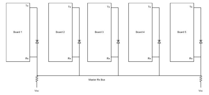
I finally have this working as suggested by Pito and Simonf by daisy-chaining all the boards together just on the RX port and locally tying the TX port to the RX port via a diode. The benefit as the guys have said is that all boards receive the message on the RX port (including the current speaker) and there is no bus Master board (even one is equal). You can control how this works entirely in software, so you might have in your program that some boards only speak when spoken to while other boards are allowing to initiate communications.
The circuit is quite simple and while I used two resistors (one at each end each was 20k ) it did work with just one resistor.
Very many thanks to all who offered advice and especially to Pito and Simonf
Regards,
Joe
- pict1.png (4.8 KiB) Viewed 998 times
It looks like an ingeniously simple system.
Perhaps it needs a name ![]()
“Maple bus” ![]()
In order to use the Maple mini in my project (porting it directly from Arduino Mega), I would need the I2C library to support both master and slave mode. This solution is so much easier that trying to add the slave code to the library, and while it does mean I need to write a little more code to make a protocol as others have described in the topic, it adds the functionality without any limitations.
I like ‘Maple bus’ as a term, but of course the solution works with any MCU which has a UART port.
Great forum, with lots of great ideas here, so well done to you all.
Joe
Thanks
I understand that it will work with any MCU and you can have 5V and 3.3V on the bus at the same time, which is great as sometimes there is a need to mix 5V Arduino pro-mini’s and STM32 in the same project.
So “Maple bus” is perhaps not the best name, but I couldn’t think of anything else at the spur of the moment ![]()
Though, having a single Master/Arbiter solves such issues.
But today are guys much clever than we were in the era of the dinosaurs
I’m new to the STM32 devices and this forum.
I was wondering if anyone has been working on the “maple bus” code. Does anyone have some example code or possibly a new library for this type of communication?
I had a project that used two pro mini arduinos that talked I2C. One master and one slave. I was wanting to port that project to the maple mini, but don’t want to re-invent the wheel.

