Spark Logic

Porting Marlin to STM32.

victor_pv Thu Jun 29, 2017 4:39 pm

UPDATED 10/26/2017:
In the last 2 days xC000005 and me have completed successful prints with Marlin for STM32F1, with the stm32duino-libmaple core, he printed a cat, and I printed a little Yoda-Budha.
During tests I was able to get about 50000khz pulses as max speed, which seems inline with other 32 bit platforms, and much faster than most printers should ever need. Which means at slower rates we have quite a few CPU cycles left to do other things.
We haven’t start with the LCD parts, but so far ADC, steppers and sdcard work, so printing from a computer is fully functional.

UPDATED 07/07/2017:
First version of my port to libmaple based cores. Should work on an F4 too, but so far I have just tested it with the F1, and only that it runs and there is serial communication, but not the steppers driving or the SDCard.
Compiled with Sloeber 4.1 and gcc 4.8.3. Should compile in the Arduino IDE but not tested.
I have tested it with an RCT6 MCU, but should fit fine in a maple mini as far as RAM and Flash
https://github.com/victorpv/Marlin-STM32-libmaple

==============================
Original post.

I’m starting this new thread to document the effort of porting Marlin to stm32 arduino cores.
-Shield with stepper connections etc, RAMPS can be modified:

-Boards: too many to list

  • My effort will go first to libmaple. Chriss Bar has a version based on STM32GENERIC core. Both cores work on some F1, F3 and F4 MCUs

-Software:
There are at least 2 ports running in STM32.

My plan:
Take Chriss code and make it compile in sloeber.
Once so, take it to Danieleff core, and make it compile and resolve any issue.
Test it with a Nucleo board and generic boards.
Add HAL for libmaple core

All the above should be feasible from a first look at the code.
We already have:
-Arduino compatible pin functions.
-Arduino compatible spi functions.
-Arduino compatible ADC functions (with more resolution, may need to trim)
-PWM functions (even if with some different parameters and setup than Arduino, still same functionality or more)

What needs to be done:
-Go thru each file in the HAL and modify/optimize for stm (just a few things)
Stepper control
Temperature probes and hotbed control
Memory usage.
Pin access.
Timers setup and usage.

Replies

ahull Thu Jun 29, 2017 4:45 pm

Hi. This might provide the motivation I need to start constructing a 3D printer from scratch, which is a project I have been meaning to undertake for a while.

Do you envisage this being doable with say a bluepill or MM, a hand full of ebay stepper motors and stepper driver boards?

victor_pv Thu Jun 29, 2017 6:45 pm

[ahull – Thu Jun 29, 2017 4:45 pm] –
Hi. This might provide the motivation I need to start constructing a 3D printer from scratch, which is a project I have been meaning to undertake for a while.

Do you envisage this being doable with say a bluepill or MM, a hand full of ebay stepper motors and stepper driver boards?

I haven’t done a pin count, but I think a maple mini will most likely do, at least for a printer with 1 extruder and 3 axis.
Quick pin count:
4 steppers, 2 pins each, 8 pins.
Bed heater and thermistor: 2 pins. (1 ADC + 1 PWM)
Extruder heater and thermistor: 2 pins (1 ADC + 1 PWM)
SD card if needed 4-5 pins (don’t remember of the top of my head).
Display: There are several options, I think common ones take 4-6 pins.
USB port: 2 pins
Optional: serial, connected to wifi printer bridge, 2 pins.

All this run in an AVR, I dont see how it wouldn’t run in a mini as far as RAM and Flash.

Optional hardware not critical to have:
-Rather than use a bunch of pins for an LCD, use the same SPI as the card and 1 extra CS pin, but this would involve writing an LCD interface.
-Serial not needed, but would be nice to connect an ESP8266 programmed with this (I have compiled and uploaded it with Eclipse/Sloeber successfully):
https://github.com/luc-github/ESP3D
-Sd card interface: You can instead print from the host. I actually never connected my printer to a host, ever, just print with the sd card so I dont have to keep a host connected for a 4 hour print.

ahull Thu Jun 29, 2017 7:26 pm

Sounds doable, don’t forget, we get USB serial on a MM or Bluepill which you don’t get on an AVR.
I think this sounds like a pretty useful idea.

victor_pv Thu Jun 29, 2017 9:18 pm

[ahull – Thu Jun 29, 2017 7:26 pm] –
Sounds doable, don’t forget, we get USB serial on a MM or Bluepill which you don’t get on an AVR.
I think this sounds like a pretty useful idea.

I think so. Not only doable, but we should end up with a nice controller, and using an RET6 MCU we should have ram and pins to spare for any expansion, but even the CB ones should fit the current Marlin.
Do you want to help spread the load?
I recently bought a 3d printer for my kids, which I am enjoying much more than then, specially building it up, so I can give you some advise on parts and what not.
EDIT:
From reprap.org
Firmware binary size between around 50 kB and 100 kB, depending on options.

victor_pv Fri Jun 30, 2017 4:00 am

I did a pin count and with a maple mini we should have enought pins for the following:
  • sd card
    sd card detection switch
    serial 1
    USB
    3 axis steppers
    3 extruder steppers (or any conbination of the 6, such as 4 axis and 2 extruders
    3 extruders temp probes
    3 extruders heaters
    bed temp probe
    bed steppers
    2 CS pins for SPI, for sdcard and a display
    1 pin left (could be used as CS for a touch panel in SPI)
    PB2 and PB8 not used (can be used as outputs once the mcu is booted, so we should be able to use them)

I haven’t looked in detail to all the peripherals needed, but I think we have enough timers,and definitely enough PWM pins.

ag123 Fri Jun 30, 2017 5:54 am

[ahull – Thu Jun 29, 2017 4:45 pm] –
Hi. This might provide the motivation I need to start constructing a 3D printer from scratch, which is a project I have been meaning to undertake for a while.

Do you envisage this being doable with say a bluepill or MM, a hand full of ebay stepper motors and stepper driver boards?

imho a simplier approach is to buy one of those cheap 3d printer kit and later swap the controller board
i’ve been contemplating creating a delta-3d from scratch but later find that it would be too much efforts to create the individual components to the precise dimensions and the total costs of purchasing the parts say from ebay actually exceeds that of buying a kit which these days go for $200 and even below.

some of those things has been discussed in this thread
http://www.stm32duino.com/viewtopic.php?f=45&t=2082

my thoughts are that we should perhaps target the f407vet6 or zet6,zgt6 board directly rather than stick with stm32f103 (though it is a possibility as well). the main thing is that m4 (f407) has 2 fpu in the cores and that would significantly speed up path computations and of course the f407vet boards has a good number of gpio pins to do all that interfacing and has a good amount of sram and flash to play with. in addition a good number of those f4 boards from ebay has that micro sd card slot built on board which is an additional convenience
for stm32f103 the ‘common’ boards apparently are blue pills & maple mini while for the bigger boards e.g. vet and zet, the price differential pull so narrow compared (some priced same or higher) to say f407vet6 black. it would literally make sense to simply get f407 boards directly in that case given the much higher performance

with f407 i’d even envision that one day it may be possible to simply send it an ‘STL’ 3d model file, the f407 do all that slicing & 3d print it on the fly! that’s possible due to the fast fpu

ag123 Fri Jun 30, 2017 6:06 am

we could also perhaps create a thread in marlin firmware forums so that interested individuals there could join the effort
http://forums.reprap.org/list.php?415
this thread would actually make sense to belong ‘there’ given it is about running Marlin on stm32
but the forumers there would likely be less familiar with available stm32 boards and features ‘out there’ and its ‘technicalities’ compared to us here
we could also get various tips / from the ‘3d printing people’ as beyond just the electricals / electronics. 3d printing is really a domain on its own
things like dealing with bed leveling, extrusion speed, head movements acceleration / deceleration, delta 3d movements, types of materials and the 3d printing problems etc are really quite specialised domains of knowledge which the ‘3d printing experts’ are probably familiar with

the other idea is to start with RAMPS
http://reprap.org/wiki/Arduino_Mega_Pololu_Shield
as the interface board as this board and the pololu motor control socket modules is actually sold on ebay and readily available (decently low costs as well)

ag123 Fri Jun 30, 2017 6:28 am

[victor_pv – Fri Jun 30, 2017 4:00 am] –
I did a pin count and with a maple mini we should have enought pins for the following:
  • sd card
    sd card detection switch
    serial 1
    USB
    3 axis steppers
    3 extruder steppers (or any conbination of the 6, such as 4 axis and 2 extruders
    3 extruders temp probes
    3 extruders heaters
    bed temp probe
    bed steppers
    2 CS pins for SPI, for sdcard and a display
    1 pin left (could be used as CS for a touch panel in SPI)
    PB2 and PB8 not used (can be used as outputs once the mcu is booted, so we should be able to use them)

I haven’t looked in detail to all the peripherals needed, but I think we have enough timers,and definitely enough PWM pins.

there could be up to 6 end stops (limit switches) in addition, if we use 1 gpio pin for each, that alone takes 6 pins
and more than likely we’d still want to interface our ILI9341 LCD display, i think the total pin count considering all that would lead us to run out of pins on blue pill or maple mini

racemaniac Fri Jun 30, 2017 7:02 am

would we then want to go for a bigger board? or go for 2 bluepills/maple minis and have one be a slave of the other (i can imagine on the main board to just initiate a circular dma spi communication with the slave via DMA, so the slave keeps transmitting a region of its memory (containing limitswitches/temp probes/ other easy things to share) to the master, solving the pin count problem :)

victor_pv Fri Jun 30, 2017 1:00 pm

My idea is not to target a single board or a single MCU, but rather a core.

There is already a port for STM32F4, but uses the HAL, and may be even the SPL. I linked it above. That is less portable, and requires more code written in the Marlin HAL, but is running already. That’s why I want to give a try to port it to libmaple and STM32GENERIC, and possibly the STM32GENERIC will also work on STM’s core.

In the pincount for a maple mini I totally forgot the Endstops, but we can include 3 end stops if we reduce the heads to a single 1. So we still could have 3 extruders with a mixing head. Or instead 2 extruders and 2 heads.
Ayway I am not specifically targetting maple mini. We will see what resources are needed, and based on that will know where it fits. I do not think the current Marlin will benefit from having an FPU. It just doesn’t seem to need it, all the other ARM ports use M3 except the current port for the Nucleo, and that probably doesn’t use it much since Marlin doesn’t use much floating point calculations.
I dont want to rewrite Marlin, only write the HAL part so it runs on STM32 boards with a valid arduino core. That’s our advantage, targetting a core we can choose the board that fits best with little or no modification. In F1 series we can use up to F103RGT6. That’s 1MB of flash and 96KB of RAM. If a 16Mhz avr 256 can run it, the F1 range can definitely run it. But if Marlin starts using more floats and we want to use an F4, we will be covered in any of our cores :)

I believe ones that is done, since we have an arduino core, it will be easier to keep those boards compatible since other libraries will work easier (lcd, keypads, graphic libraries…)

Racemaniac idea is interesting, but needs to be some way that is done totally in the HAL, otherwise we would have to rewrite parts of Marlin, and I don’t want to do that to keep it 100% compatible.
If you guys want to start checking the current HALs for other MCUs, that’s our starting point, and will show what’s supposed to be done by the HAL. Hopefully most actual IO goes to the HAL.

ahull Fri Jun 30, 2017 3:56 pm

You could put your endstops on a single analog pin with a resistive ladder. You can actually mux an entire 4×3 switch matrix with only one alalog pin and some carefully chosen resistors.

http://www.instructables.com/id/Arduino … ix-Keypad/

I am of course assuming the end stops are mechanical switches, for photo interrupters, you can probably do something similar, but you would need to think through the values.

ag123 Fri Jun 30, 2017 8:19 pm

out of curiosity, i took a look at the marlin source codes

there is the RAMPS pinmap
https://github.com/MarlinFirmware/Marli … ns_RAMPS.h
http://reprap.org/wiki/Arduino_Mega_Pololu_Shield

a full ramps implementation do need quite a large number of pins
– 6 pins limit switches
each stepper motor controller seem to take 4 pins (step, dir, enable, cs, i’m not too sure if we can simply use enable without cs)
3 motors for each of x, y, z – 12 pins
1 motor for extruder 4 pins
1 motor for 2nd extruder (if you are using it) 4 pins (optional)
total 16 pins for motor (assuming only 1 extruder)
– temperature sensor
1 analog pin – hot end
1 analog pin – bed (for heated bed)
1 analog pin – for hot end2 (optional)
– mosfet
– 1 pin for mosfet hotend (the heating element)
– 1 pin for mosfet hotend (the heating element – hot bed)
– 1 for mosfet fan (if we leave the fan on we could save this?)

for ILI9341 LCD 7 pins
SPI (/CS, CLK, MOSI, MISO) 4 pin
C/D (command/data) 1 pin
tft_reset 1 pin
backlight 1 pin (optional)

beeper 1 pin
#define BEEPER_PIN 23

button switches & kill switches 3 button switches + 1 kill switch – 4 pins
#define BTN_EN1 35 // reverse if the encoder turns the wrong way.
#define BTN_EN2 37
#define BTN_ENC 31
#define KILL_PIN 41

SD card assuming SPI 4 pins ( /CS, CLK, MOSI, MISO)

hence a ‘full ramps’ setup for an x-y-z (possibly similar for delta) printer would take quite a good number of pins and would exceed that of a single maple mini or blue pill.

we could possibly daisy chain several maple mini or blue pill together say use I2C but that’d need some enhancements to the marlin codes and we’d also need to create/write the codes for the ‘co-processing’ maple minis, blue pills, e.g. we can split them up into ‘modules’ so that perhaps 1 MM/BP do motors, 1 do mosfets & limit switches & analog pins, the ‘main board’ does ILI9341 LCD + SD card and runs the core Marlin codes

actually there is an interesting twist with Maple mini/ Blue pill, we can have 2 (or 3) MM/BP boards talk to the host computer (it can be a mini pc e.g. intel compute stick) over usb-serial so that perhaps we divide the functions, one do motors, another do mosfets, limit switches & adc (temperature sensors)etc. then we run a ‘software marlin’ on the host computer, interpret g-codes and send the commands over to the ‘co-processing’ MM, BP over usb-serial.

then there is a teensy pinmap (nxp’s arm)
https://github.com/MarlinFirmware/Marli … _TEENSY2.h
this seem to use significantly less pins e.g. only 1 pin for each motor, my guess is that this is a ‘stripped down’ config vs a full RAMPS like board
this doesn’t seem like a ‘complete solution’ and i’d guess for a ‘full ramps solution’ multiple teensy would be needed

given this it is possibly simpler if we target or assume that we are working on a STM32F407VET or ZET board that has ‘all the pins we need’
in that way Marlin plus all the IO control codes (all the motors, mosfets, temperature sensors, LCD, SD card, limit switches, 4 panel buttons, beeper) run from a single board and mcu

victor_pv Sun Jul 02, 2017 7:17 am

The majority of boards just leave the steppers always enabled, so that saves 1 pin per stepper, and same for CS, so they just use 2 pins, steps and direction.
For the endstops, a normal carthesian printer uses just 1 end stop per axis, so only 3 pins are stricly needed.
At the end of the day, I think a maple mini would make a nice basic board, faster and more precise than an AVR based one, but still a basic printer.
Now, a RET, even and RCT, has plenty of pins for anything, and much more memory and RAM.

I just got the first compile of my HAL (not tested yet, just compiling), without including any LCD:
section size addr
.text 87836 134225920
.text.align 4 134313756
.ARM.exidx 8 134313760
.data 3312 536870912
.rodata 7640 134317080
.bss 5032 536874224

This uses the USB Serial, and SDFat with DMA. Our usb serial I think is currently one of the fastest of any core, and same with SDFat reading.
So this is taking 87KB of flash, and 8KB of RAM. I tested a compile with an AVR Mega but forgot to save the section sizes, but if I remember right was about 90KB of flash.
I think this is pretty good given that’s a 32bit MCU.
This is based on libmaple core, so should work in a lot of F1 and at least a few F4.
It uses the SPI library, the Timer library, and some basic stuff (pinMode, hw watchdog).

I will try to compile with some LCD next, and also compile for a Mega just to have a reference. Oh and actually flash this to a mini and see if it’s alive…

EDIT:
Similar options compiled for the Mega: (there is no separate rodata here, it’s accounted for in .text)
section size addr
.data 228 8389120
.text 68330 0
.bss 3545 8389348

So it uses some 20KB less total, and 3.5KB of RAM. I think the libmaple version on a 32bit mcu and using DMA and other hw resources where possible is a good choice.
With a few more KB of flash and RAM we could run a nice color touch screen and still have cpu time to spare.
And this is still with Marlin’s code which is pretty messy and written for the AVR. As an example the pins are driven high and low one by one in a ISR called from a timer interrupt… Even the pwm for the heaters FETs is driven writing high and low to a port rather than using PWM…

victor_pv Sun Jul 02, 2017 2:54 pm

It may be if it has been programmed diferently.
I get a feeling a firmware programmed from the start for an MCU with more resources may have been done in a way that’s easier to understand and to port.
The advantages of Marlin for being ported right now are that there is the official STM port for their HAL, and comparing that to the same release of Marlin shows what they had to do, and that they want to move to 32 bit MCU and have already started separating things to a HAL.
So having an STM32 HAL at this point, hopefully as it gets extended to more features, or to take advantage of better mcu resources will be an evolution, rather than start from scratch.

My version of the HAL compiles fine so far. I need to burn it in a board and see what it does, hopefully work without too much trouble.
I read that link to the italian forum that you posted. Someone wanted to port MarlinKimbra 4 due to the STM. That’s an offshot of Marlin that the italian guys did for multiextruder, and seems like they kept evolving it, and in those posts they commented on how the code was cleaner. So perhaps can be ported too.
I just don’t know which one is more features rich, but seems like Marlin has a very active group of people looking at it.
And one of them is no other than Bob Cousins, he knows this core pretty good since he was very involved in upgrading the initial libmaple for a while before handing it to Roger and going to other pastures. Hopefully he can provide some guidance with the STMs.

Anyway I’ll post my code today to github, and if I get a chance debug it a bit on a board.

ag123 Sun Jul 02, 2017 5:22 pm

no worries, victor, i appreciate your efforts and sticking with marlin is probably a best solution after all. it is a ‘most prominent’ open sourced 3d printing firmware ‘out there’. if we make enhancements, e.g. to organise codes so that they could more easily be ported / run on different platforms, it would benefit marlin itself too. ideally, what we do could hopefully be part of the ‘official’ marlin, that’d be really good :D
i’m still waiting for my ‘slow boat’ RAMPS card to arrive. but in the mean time, i’d need to try out STM32GENERIC so that later hopefully i may be able to join the efforts as well

victor_pv Sun Jul 02, 2017 7:47 pm

The firmware is running in an F1. This is an RCT6 mcu, just to plug the j-link to it.
I have not been able to correctly calculate the free memory, that’s why it shows that weird value, but shouldn’t affect. There is nothing connected, so it reads weird temperatures and things like that, and haven’t tested any output yet.

Connect to serial portCOM3 at115200
start
echo:Marlin bugfix-1.1.x

echo: Last Updated: 2017-05-04 12:00 | Author: (none, default config)
Compiled: Jul 2 2017
echo: Free Memory: 134375576 PlannerBufferBytes: 1280
echo:Hardcoded Default Settings Loaded
echo: G21 ; Units in mm

echo:Filament settings: Disabled
echo: M200 D3.00
echo: M200 D0
echo:Steps per unit:
echo: M92 X400.00 Y400.00 Z400.00 E108.00
echo:Maximum feedrates (units/s):
echo: M203 X150.00 Y150.00 Z150.00 E25.00
echo:Maximum Acceleration (units/s2):
echo: M201 X1000 Y1000 Z1000 E10000
echo:Acceleration (units/s2): P<print_accel> R<retract_accel> T<travel_accel>
echo: M204 P1000.00 R1000.00 T1000.00
echo:Advanced: S<min_feedrate> T<min_travel_feedrate> B<min_segment_time_ms> X<max_xy_jerk> Z<max_z_jerk> E<max_e_jerk>
echo: M205 S0.00 T0.00 B20000 X10.00 Y10.00 Z10.00 E5.00
echo:Home offset:
echo: M206 X0.00 Y0.00 Z0.00
echo:PID settings:
echo: M301 P17.17 I0.88 D83.88

chrissb Mon Jul 03, 2017 3:13 am

Cool to see people working on this here! I’ve been playing with running Marlin on an F4-based board for a while now, one of my previous attempts is mentioned in the first post.

That repo (https://github.com/chrissbarr/Marlin/tr … Fix-F446VE) was my first ‘successful’ attempt to get Marlin running on an STM32 microcontroller – I’ve used it for a few dozen print jobs at this point, but I was unhappy with it a for a few reasons. Firstly, I didn’t have a way of compiling the code in the Arduino IDE – users would need to download SW4STM32 to compile the code, edit their configuration, etc. Secondly, there were a few places I did some fairly ugly hacking away at the Marlin code to get things compiling and working nicely, so it probably wouldn’t be easy keeping it updated with Marlin, nevermind getting it pulled into the master. Third, as you can see in that repo I have the entirety of the STM32 F4 HAL dumped in a subfolder within Marlin, which is a lot of files – I don’t know how keen the Marlin folks would be to have all that added to Marlin, and I’m not even sure if the licenses are compatible.

My current approach, which I haven’t yet printed with but is 90% of the way there, is hopefully more flexible. I think others in this thread have suggested using danieleff’s STM32GENERIC core, and that’s my current approach. I have a fork of that core here, and all I have done is add support for the F446VET6, and support for a custom DFU-based upload method. I have compilation + upload via USB-DFU working from the Arduino IDE, though this does require a custom bootloader on the F4 to work at present.

I have an updated fork of Marlin here. Thanks to Marlin’s evolving HAL and the STM32Generic core, this fork has required far fewer changes to the Marlin codebase. There are a few areas where I have had to tweak things, but I think many of the changes I found I had to make have been made by others in the most recent Marlin HAL work – I need to rebase my work off of the latest Marlin HAL, and I think when I do that there will be very few changes I’m making to the actual Marlin code.

This current approach has the following working:
[*]Thermistors
[*]Endstops
[*]PWM for heaters / fans / buzzer
[*]Stepper drivers via SPI (TMC2660)
[*]20×4 Character LCD (RRD Smart Controller)
[*]Serial over USB
[*]EEPROM emulated in flash

The current ‘structure’ is composed of these elements:
[*]Fork of STM32GENERIC core
[*]Fork of Marlin with HAL and minor modifications
[*]Custom bootloader to handle DFU-uploads + leave space for EEPROM in flash

I’m basically at the point where it’s ready to test on a printer, I just need to tidy up the code a bit and give it a go. Just need to find the time to do some testing!

Here are some images of different parts in action, for anyone who’s interested:

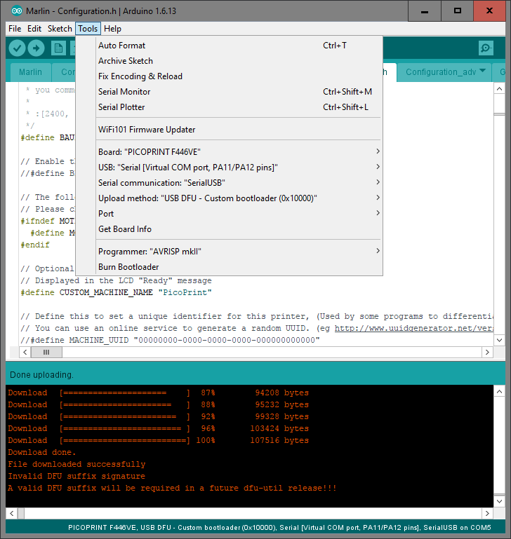
Image
Upload from Arduino IDE

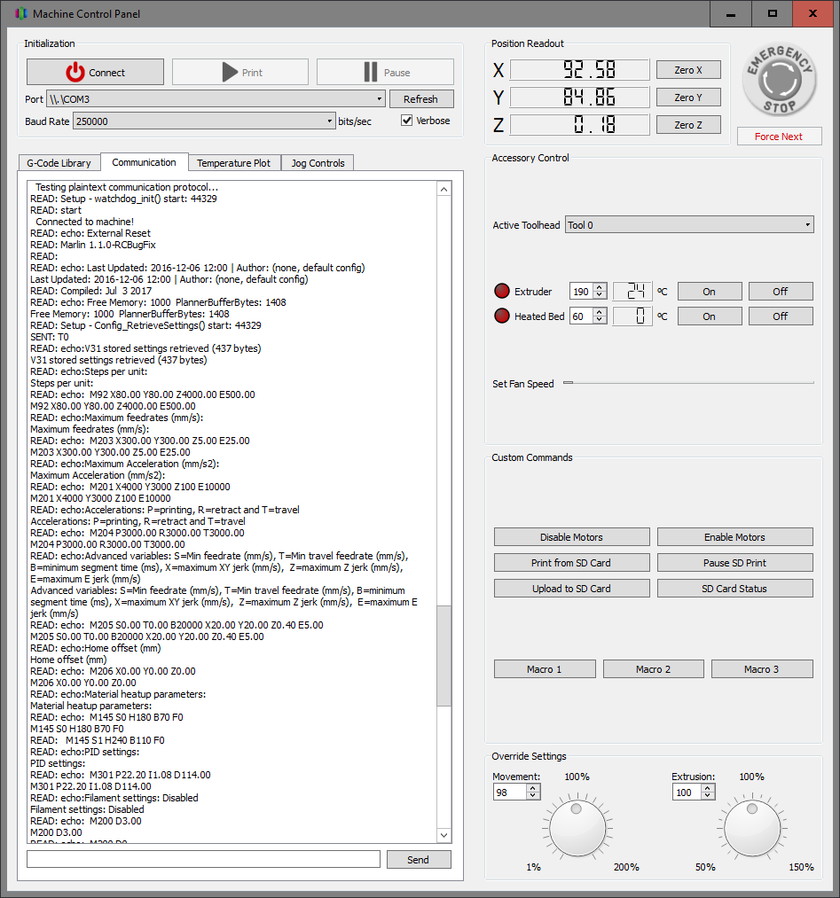
Image
Serial comms via USB working

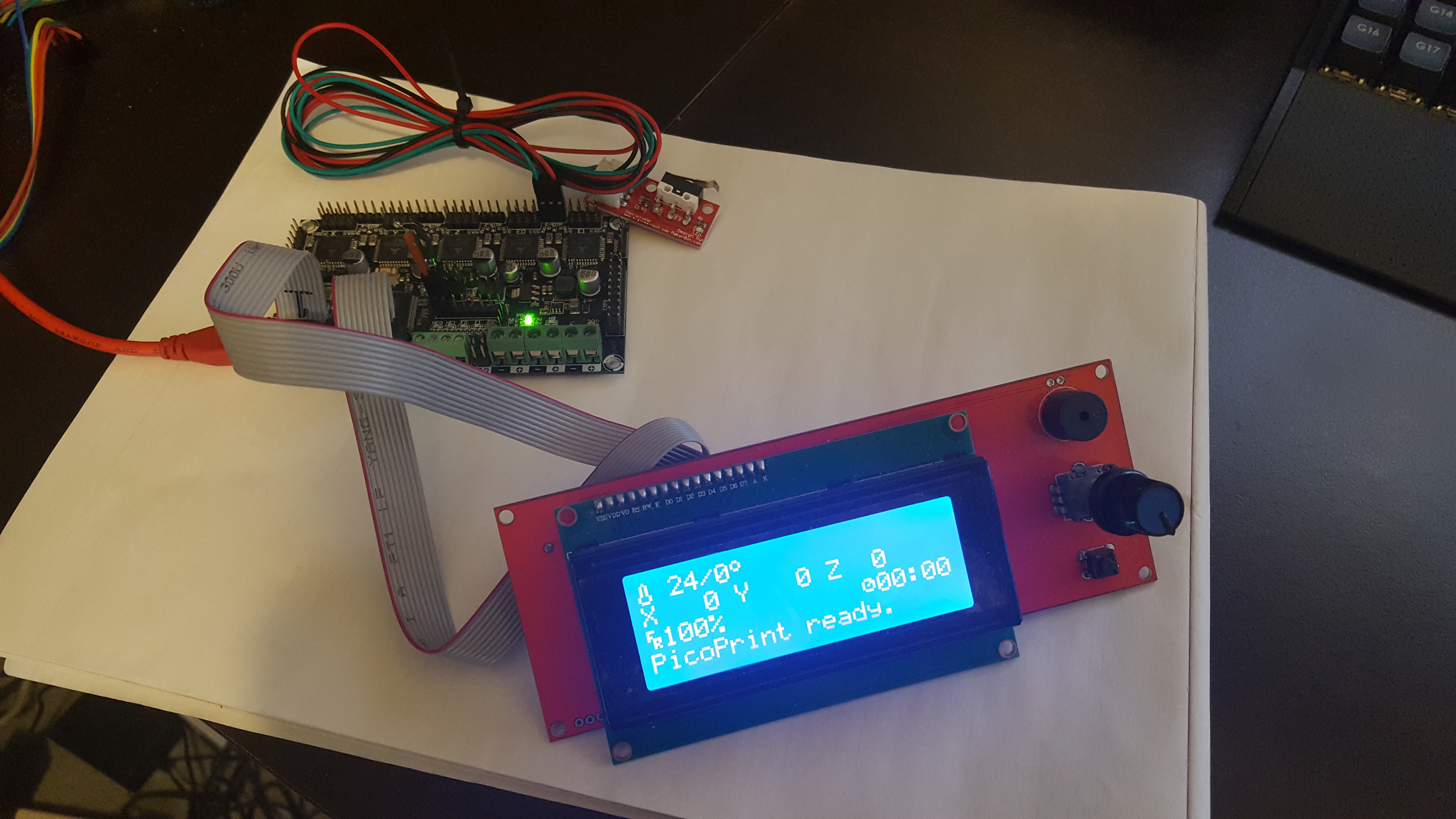
Image
Board working with LCD and thermistor

I still have a lot to do before everything is working nicely and neatly, but if anyone else is trying to follow a similar path I’d be happy to provide any info I can.

victor_pv Mon Jul 03, 2017 6:11 am

Hey Chriss, I’m the same one that posted in github about porting to STM32 and you shared your repo. I opened this thread here to keep track of my progress.

I need to check the newer one based on STM32GENERIC, but as far as we dont hack Marlin much we should be able to port it to multiple MCUs and keep it updated.

I started with the port to the libmaple core and have a few things running already. That once has normally an advantage in speed and code size over the HAL based one, but in return it’s more difficult to adapt core from one MCU to another, although there are F3 and F4 versions that are very functional. Things like spi, timers, gpio, usb, usarts, work in all of them.

I’ll be happy to help with that HAL too.
I used the LPC fork to start with since someone said that fork is fairly up to date and the LPC HAL is functional.

About the DFU bootloader, that would be a nice adition for the F4 boards. Most people around here use stlinks and jlinks since the bootloader we use for the F1s has not been ported to other series.
I don’t know if that’s all your code or borrowed, but if it’s yours it would be great if you give it a free license and can be used by everyone, and possibly make it compatible with as many MCUs as possible, and add compatibility with the F1 bootloader so a single set of tools work for uploading, but that’s a whole other subject.

What board are you using in those pictures, is that a custom one?

About the LCD, I was planning to not even test text screens, and go directly for nice color TFT since we have plenty of display drivers working with the F1, and take advantage of the cpu resources, but that’s down the list after steppers, thermistors, temp… are working.

EDIT:
Just had a quick look at the HAL in this repo:
https://github.com/Aus3D/Marlin/tree/32 … /HAL_STM32

Are you using software SPI? I dont see the HAL SPI functions, neither the arduino standar ones.

Sign in to reply