The solution in this post works fine:
http://stm32duino.com/viewtopic.php?f=1 … 766#p42769
If you don’t have a 10K pot at hand, you can replace with a couple of resistors, or with a single 2k to 10k resistor to ground and connect the PAM input to the common point between the 2 caps and the resistor.
=================================================
I’m not an expert in audio but wanted to connect a PT8211 DAC to a PAM8403 amplier:
PMA8403 amplifier
I tested sending square and sine waves to the PT8211. The PT takes int16 (complement 2) and anything over the rage of +-5 seems to be too much, and I get increasing noise.
I tried a direct connection, then a connection adding a 47uF cap, but seems like the PT8211 output is too high for the PAM8403 and I get more noise than anything else as the volume increases just a bit in the PT8211.
I tested adding a 100ohm serial resistor, and didn’t change much.
Anyone has experience with either and can recommend resistor values, RC network, or something else that worked for them?
P.S. I got the Helix mp3 player working in the new bluepillF4, with an F103RCT6 MCU, but sadly I can barely hear it over the noise since it seems the output is too high for the PAM and is clamping.
Takes some 40KB of RAM between buffers and what not, but I think it can be optimized further.
https://www.electronics-tutorials.ws/at … uator.html
You will need to block the DC and then use an attenuator… a series resistor and a rheostat across the input … technically, a potentiometer would be better so that you can adjust the input voltage and maintain a 600 Ohm impedance to the amp (or whatever the spec states Zi is for the unit.)
Ray
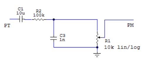
- PT to PM coupling.JPG (15.24 KiB) Viewed 512 times
You may try with R1 made of 2 resistors simulating the potentiometer. No idea on the signals levels, so you have to play with a bit. ![]()
Thus 1:50(25), like 100k/2(4)k where 2(4)k is the potentiomer’s value.. Has to be elaborated in situ
BTW there is a higher-order low-pass at the PT’s output recommended in the datasheet (with an op-amp).
I will try with the values you recommended (100k/2(4)k )and see if I can get something acceptable. I’m not trying to get the best possible sound and gain, but just so I can hear something clear coming out of the speaker and I know the MP3 is being decoded right and that’s not choppy due to decoding taking too long, etc.
If I can get the sine wave playing somewhat clear over the full input range of the DAC with those resistors without clamping or too much noise then I should be able to play other sounds too.
I’ll keep you guys posted, thanks!
PS: I ran this mp3 player many years back on the F4discovery and it worked fine
https://www.aliexpress.com/item/Free-Sh … 23393.html
It works quite well on the Arduino UNO PWM Tone output and it’s powered from Arduino (the USB PC at last).
There are a lot of small schematics about this chip but I didn’t find the schematic of my board.
https://electronics.stackexchange.com/q … ply-op-amp
You can use nearly any cheap OP-Amp for this (like TL07x, LM32x…) For stereo twice the circuit and use a dual OP-amp (TL072…).
Edit: Ok, this is – more or less – done with the application circuit (with LP-filters) so you have line output level. As I can remember this circuit is a “must have” and not an option.
Edit2: If you need some more audio circuits I would prefer a voltage converter for a negative power rail. ICL7660 is your cheap friend, for more serious applications use the LT1054
first 47uF in line, then 100K resistor in line too, then 1nF cap to ground, and I tried 2 different resistors values simulating the pot, 10K and 2k. Both work fine with small caveats.
The 10K reduces the volume further, but eliminates clipping completely.
The 2K gives a higher volume, but depending what’s playing there may be some clipping.
I’ll update the first post for anyone ever searching the forum about that.
After that I didn’t have clipping, but the noise was all over the place still, so I checked my connections and further found out I had a floating PB12 pin, need to resolder the MCU pin to the board.
Apparently that was not a problem with the waves because of the values I was using, so part of the issue with noise after using an amplitude larger than 5 was due to the WS signal not actually going to the DAC. I checked it with the logic analyzer and the floating line was someway bouncing with data, I guess it was getting coupled strong enough.
So after correcting the floating pin and having the right input to the amp, the square and sine waves played fine at any volume, but the mp3 player still had noise all over the place. I checked again with the logic analyzer, and looked like the data was shifted one bit to the right (like the Phillips format, rather than the japanese format). Checked again with the simple wave player and that did not happen, so I went to check the i2s library, and found out a function I added to change frequency any time had a mistake, corrected that, and now it plays great.
I tested a 22Khz, 64kbps file, and decoding a frame takes around 5mS, playing the same amount of samples (1152), takes 26mS, so it will need 25% cpu time for decoding.
With a 44.1Khz, 265kbps file, decoding takes 11mS, and playing the samples would take 13mS, so it leaves 2mS for everything else.
I use DMA for the I2S, with callbacks (non blocking) and DMA for the SDIO (blocking).
Next I need to adapt this to RTOS, so the SDIO can yield to another task while waiting for the DMA transfer to complete, and possibly use another DMA channel for moving data in buffers (currently using the CPU).
I’ll upload the code to github later today.
@Zoomx, I just ordered one of those with a pot, thanks for the advice.
@Madias, I don’t have any opamp at hand. I have some transistors, and 2 of the PAM boards, so I though it would be easier and quicker to use the PAM, at the end of the day using a couple of transistors would have been the same trouble or less.
It has ADC, 2 DACs, 2 I2S, and a fair amount of flash ram and cpu power.
Anyone interested in designing a simple pluggable board with a PT8211 DAC, and whatever is needed for input (op amps, filters, etc)?
I don’t have enough knowledge on managing audio signals (should have it from my school years, but forgot it all, so I am almost useless in that regard), but I can help with the code, and still have plenty of bare bluepillF4 boards, can send some to anyone interested.
Currently with libmaple SDIO works good with the onboard connector in that board, so there is storage, we just need the audio circuitry.
Most of the cheapo modules with various audio stuff on them are designed sub-optimally..
Here is the freq characteristics of the divider (single channel) for C3=200pF..5nF step 200pF, while the volume regulator in the middle (5k-5k), R4 is the internal Ri of the module.
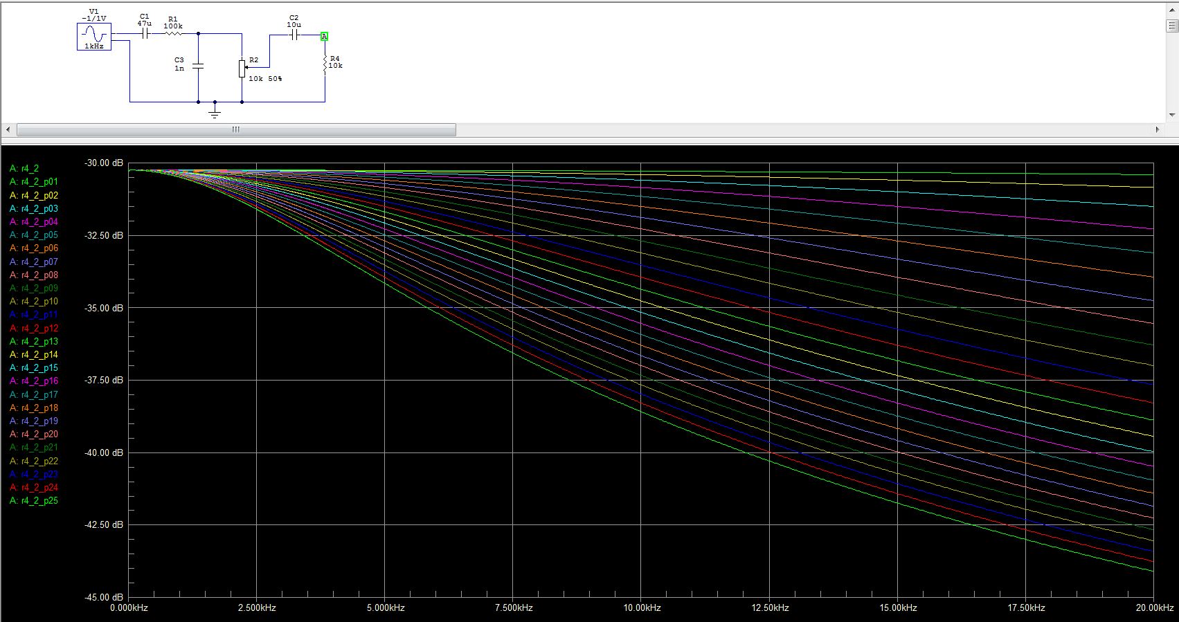
- Freq Char.JPG (228.7 KiB) Viewed 304 times
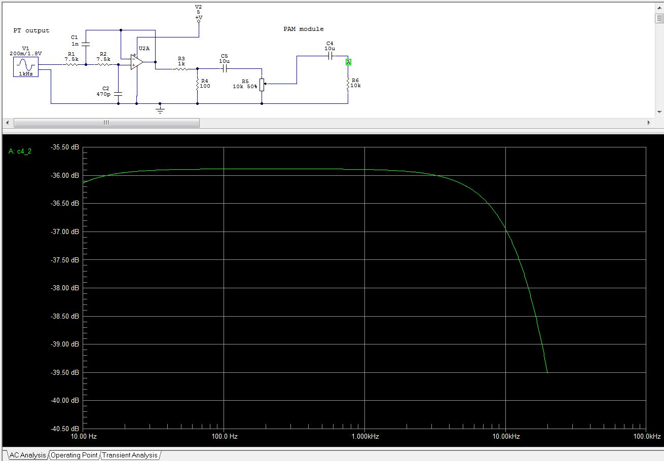
I would use this schematics for the wiring of the MCU->PT->PAM modules (a single channel shown).
The C4 and R6 are the PAM’s module internal input components (from the pcb picture at aliexpress). The C4’s value is an estimate.
The divider R3/R4 is now low-impedance, thus you may use almost any value of the R5 potentiometer if R5 >=1k (with lower R5 values increase the C5 to 100u in order to maintain its high-pass cut-off freq) .
The R4’s 100ohm value has to be elaborated such the output of the PAM is not over-driven (not distort) when the potentiometer is at “full” (the wiper at the higher end) position with max PT output amplitude.
I would start with R4=56ohm while measuring the signal at a dummy 8ohm (4ohm) resistive load wired instead of the speaker (mind it is a D class amplifier so you most probably will see ~250kHz switching as well). While feeding in an 1kHz sine test signal with max amplitude the PT can provide, measure its shape at the 8ohm.
Best use the FFT option of your lovely oscilloscope – no harmonics shall be visible ![]()
Needs some experimenting with real hw, sure.. My guess – you would need R4=56-82ohm in order to get a clean output with max PT amplitude and wiper at full..
The PT output has got an active low-pass with 20kHz bandwidth (as depicted in the PTs datasheet). Use a single supply, rail-to-rail OPAMP. Do not use 2 opamps in a single package. Decouple each opamp package with 10uF || 100n close to their Vcc/GND pins.
The power supply wiring – a good decoupling is required, “star wiring with Vcc and GND module’s wires” with a single common ground GND POINT and a single common battery Vcc POINT.
The C9 shall be 470uf-1000uF/6V best (the datasheet recommends 1000uF)..
The “5V” (or 3.3V – plz double check) should be a good filtered source capable of providing at least 1A current.
Provided as-is, no warranties of any kind are provided..
.
- Real circuit.JPG (107.15 KiB) Viewed 251 times

