Danieleff has released a HALMX based core that seems to use the same resources as libmaple and provides compatibility with multiple MCUs since the HAL MX layer is similar between them. Since the F4 libmaple core doesn’t provide a measurable advantage and is older and incomplete, it is better to focus to on the HAL MX ones.
Currently there are 2, one from Danieleff and one official from STM.
We recommend anyone wanting to use or develop for the F4 to work on those cores rather than the libmaple one.
**********************************************************************************************
**This post will be updated with major progress, or links to specific threads, boards, etc **
All,
There seems to be a lot of momentum around the cheap F4 boards, be it from flight controller (405), from alibaba (407 and others).
I think if we organized a bit the work that needs to be done on those boards, we could as a group be more productive.
Rather than 4 people spending their time trying to blink a led, 1 person works on gpio, 1 person works on something else, and we put it together with clear instructions, and once tested if we need changes to the core we send clean PRs to Roger.
Anyone else thinks this is a good idea? If so, what would you help with?
-Victor_pv: I volunteer myself to review the SPI library and add DMA support to it with functions similar to F1. Once completed I will try to work on an i2s library. Next, if could be 2nd depending on interest, port FreeRTOS.
Blackboard: http://wiki.stm32duino.com/index.php?title=STM32F407
If anyone wants to help on testing or developing, you can post in this thread and I will add it to the list.
Working:
GPIO (several people testing, seems to work)
SerialUSB (Stevenstrong)
FreeRTOS 8.2.1
Needs testing and possibly work:
SPI (Victor_pv)
DMA (Victor_pv)
i2s (Victor_pv)
ADC
DAC
Timers
PWM
FreeRTOS 9.0.0 (possibly works already since 8.2.1 worked out of the box)
i2c
USARTs
SDIO
CAN (Michael)
FSMC (Pito?)
-Stevenstrong: doing some clean up, and created new board files for the black board. Parallel displays, and usb.
Standards to follow:
Coding standards: http://docs.leaflabs.com/static.leaflab … ndard.html
RAM will be allocated from the normal SRAM block by default. CCM not used and not defined yet in linker scripts.
Board Names: Generic STM32F407V series, Generic STM32F407Z series, etc
2 current repos:
Based on Aeroquad port of libmaple: https://github.com/stevstrong/Arduino_S … F4_variant
Based on libmaple F2-F4 files and current stm32duino F1: https://github.com/victorpv/Updated_STM32F4
Progress:
USB working Steve’s repo, still needs to be tested in Victor’s.
CCM ram can be used on Victor’s repo (Currently used for pin_map and .bss area, provides speed gains in whetstone test)
FPU working on both repos. Details in separate thread.
GPIO working on both. Different implementation in the latest libmaple code, may require changes.
Current issues:
Everything not confirmed as working.
Pito trying to get USART working at Mb rates, reply on this thread if you can test it.
right at the moment, i think on the STM32{V,Z}ET6_black (that specific board) there are some ‘headaches’ on an optimal default mappings as to which physical pins on the headers is going to do SPI, which are going to do analog (assuming an A1- A6 arduino uno profile), which are going to do I2C and which are going to do UART
one of the issue seemed to be that the board designer has put an spi flash, and the SPI1 ‘headers’ and an nrf24 connector, all on the same pins
this would probably mean that if you are going to use SPI and i2c on the nrf24 connector, use the onboard spi flash (part of the board) and drive an lcd on spi1 there may be some overlaps / conflicts
but nevertheless that board has lots of pins broken out and i’d think it shouldn’t be too much of an issue as a ‘user’ can later remap the pins they want to use for say spi + i2c
one of the other things is ‘trying things out’ this to an extent is a ‘learning process’ of the individual and to later say participate in the development perhaps of a particular component. this could actually be seen as a ‘testing’ process, as even say to start with developing the SPI interface for F4, i may start with compiling the existing F4 branch codes and figure out where it breaks. accordingly the F4 branch of codes some parts of it is pretty much working well
http://www.stm32duino.com/viewtopic.php?f=39&t=1976
hence, i’d think we’d need to see what else breaks and decide how to fix that (e.g. make a common code with the F1 branch of codes?)
I was just on beginning to touch the SPI lib…
In short what I did so far:
– cleaned up the whole F4 project from STMF2 and F1 defines
– generated new variant for black_f4 board
– generated a black_f4.cpp and .h file in the new variant root folder, which contain pretty detailed information about used board pins.
blinky example still runs with both new (black_f4) and old disco as board target.
I should commit these changes in my github repo, I think…
let me start blinking my led 1st, i’d try the f4 branch
http://www.chibios.org/dokuwiki/doku.ph … :hal:start
http://www.chibios.org/dokuwiki/doku.ph … l:features
It is covering almost all F407 peripherals and it is mature, well documented (825pages pdf), and well supported.
Q: could be that stuff reused here somehow??
Where I got bogged down was USB CDC and eventually MIDI.
The other bog spot is the Pin mapping/Pin naming. That is where I started writing scripts, and it looks like ST has opted for that approach.
When I attempted to merge the non HAL lib maple stuff, there was simply too much low level register dependency to make the two libraries interchangeable. How does one take code for a STMF429 and shoehorn it into a STMF401, then relate this code to a STMF407?
With the Maple STMF103, we had a nice simple board with a nice simple layout. The easiest way is to simply state that is the hardware package and pin map supported. That the Nucleos, DISCOs, and quad copter controllers should use the STM HAL branches, and just learn to live with code bloat.
Possibly. I think trying to make a single core work on the F407, the F401 and the F429 amounts to trying to make the F1 core work on the F103, F105, and F107. As far as I know, no one has even tried other MCUs in the F1 series.
Last but not least, there is an additional “learning by doing” effect for the “new” F4 device ![]()
I just committed my changes in my repo “Black_F4_variant” branch.
I also sent a PR for Roger, maybe he can find some time to check it.
1) do you start with https://github.com/rogerclarkmelbourne/Arduino_STM32 as the basis repository?
2) do you start with the Arduino_STM32/STM32F4 and basically use variants/discovery_f407 as the starting point
2a) then create a sketch that runs on the above?
or
3) do you start by making a copy of Arduino_STM32/STM32F1 and making that as Arduino_STM32/STM32F4
4) and creating a new STM32F4/variants/discovery_f407 say using the original variants/discovery_f407 as the base?
4a) and create a sketch that runs on (3) and (4)?
—-
oops corrections, i think i’d check out steve’s Black_F4_variant branch instead, need to catch some sleep it is almost morning here ![]()
@victor et.al
i do agree that hal is possibly a best way forwards, as apparently just by comparing the progress (i’ve not yet tried them out)
ST’s F4 core
http://www.stm32duino.com/viewtopic.php?f=48&t=1943
and
danieleff’s STM32GENERIC
http://www.stm32duino.com/viewtopic.php?f=42&t=1966
seemed to be making further progress starting with ST’s hal
libmaple is to an extent creating a hal or api to connect to the st hardware, the only difference i’d see is that ST’s core and STM32generic is basically creating interfacing api (from arduino/maple) to ST’s hal
Regarding the way to go, I think we may find a good way to combine libmaple with HAL.
For example, the USB is already set up as HAL structure, see: https://github.com/rogerclarkmelbourne/ … aple/usbF4.
So it just have to be included into the build process correctly.
I think this will be my next target.
Other peripherals can then be included similarly, or using only libmaple style, if only little work needed.
“Generic STM32F407V series”
“Generic STM32F407Z series”
I managed to get USB serial working with PlatformIO.
Attached the reworked PlatformIO files: one board definition file, and the other the build script.
There will be two new USB devices recognized by win10 x64. They need a special driver, because the virtual COM port driver from ST does not work.
I have found here (german forum) a working version, cannot attach because of the file size.
EDIT
The original ST virtual driver may work, you have to unzip the file, run the executable, and then go to C:\Program Files (x86)\STMicroelectronics\Software\Virtual comport driver in Windows Explorer and double-click either dpinst_amd64.exe for 64 bit systems, or dpinst_x86.exe for 32 bit.
I need some more time to adapt the paths within Arduino IDE. I will let you know when finished.
The communication over the USB serial is not tested yet, but is at least recognized by win10.
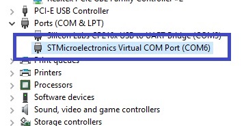
- stm32f4usbdevices.jpg (27.81 KiB) Viewed 284 times
Why you call it Board_black_F4?
We have today 2 Black 407 boards at least – VET and ZET one..
Let us agree on the names at least
The BluePill/BlackPill/RedPill is “Generic STM32F103C series”, etc.
So the 407VET and 407ZET should be named:
Generic STM32F407V series
Generic STM32F407Z series
Can you please point exactly where and what should I change?
The names: that has to be agreed upon somehow – how to call the variants, boards, menu items, how to call the -Dxxxxxx switches etc.
Some standards.. My recommendation is to agree that now, the sooner the better..
For example – today’s “naming standard” I see in repo:
genericSTM32F103V.name=Generic STM32F103V series

genericSTM32F103V.build.variant=generic_stm32f103v

genericSTM32F103V.build.board=GENERIC_STM32F103V

genericSTM32F103V.menu.device_variant.STM32F103VE=STM32F103VE

genericSTM32F103V.menu.device_variant.STM32F103VE.build.cpu_flags=-DMCU_STM32F103VE
genericSTM32F103Z.name=Generic STM32F103Z series

genericSTM32F103Z.build.variant=generic_stm32f103z

genericSTM32F103Z.build.board=GENERIC_STM32F103Z

genericSTM32F103Z.menu.device_variant.STM32F103ZC=STM32F103ZC

genericSTM32F103Z.menu.device_variant.STM32F103ZC.build.cpu_flags=-DMCU_STM32F103ZC
Line 39 I have changed a bit, I was also unsure about the correct value.
About the naming, I have nothing against “generic_stm32f407v”/z for folder names.
IDE naming: “Generic STM32F407VET6 (512kB FLASH, 128+64kB RAM)”
Any other opinions?
The problem I see coming is how to name the other, smaller, generic F407VET6 board. It will have other pinout than the black F4…
Will that be the Blue_(pill_)F4?
I think that this later should be the generic one, since it has really no restrictions on the pin usage, contrary to the black F4.
genericSTM32F407V.name=Generic STM32F407V series

genericSTM32F407V.build.variant=generic_stm32f407v

genericSTM32F407V.build.board=GENERIC_STM32F407V

genericSTM32F407V.menu.device_variant.STM32F407VE=STM32F407VE

genericSTM32F407V.menu.device_variant.STM32F407VE.build.cpu_flags=-DMCU_STM32F407VE

genericSTM32F407V.menu.device_variant.STM32F407VE.build.ldscript=ld/stm32f407ve.ld

genericSTM32F407V.menu.upload_method.DFUUploadMethod.build.ldscript=ld/stm32f407v_dfu.ld
genericSTM32F407Z.name=Generic STM32F407Z series

genericSTM32F407Z.build.variant=generic_stm32f407z

genericSTM32F407Z.build.board=GENERIC_STM32F407Z

genericSTM32F407Z.menu.device_variant.STM32F407ZE=STM32F407ZE

genericSTM32F407Z.menu.device_variant.STM32F407ZE.build.cpu_flags=-DMCU_STM32F407ZE

genericSTM32F407Z.menu.device_variant.STM32F407ZE.build.ldscript=ld/stm32f407ze.ld

genericSTM32F407Z.menu.upload_method.DFUUploadMethod.build.ldscript=ld/stm32f407z_dfu.ld
The problem I see coming is how to name the other, smaller, generic F407VET6 board. It will have other pinout than the black F4…
Will that be the Blue_(pill_)F4?
The simplest answer would be – we have about 15 F103boards, but only few generics one, nobody complained. Not sure it is the right answer, though
Imagine, with growing demand from stm32duino community, the makers will start to produce almost the same 407 boards, with 6 different pcb colors and with 20 pcb sizes and with 20 pin header assignment variants.. Who will maintain all that stuff then? We do not use arduino’s pin numbering, but PC12, PG4 alike-type. The peripherals are almost the same. The only major difference could be the flash size.
With those F4xx there is zillion alternate functions and maybe pin remmapings. That is difficult to manage with ANY number of variants..
If there is a consensus the only “interface” towards the user is the pin numbering schema derived from MCU’s pins – like PA10, PB4,.. – then using generics (based on an MCU package) is ok, imho.
The switching on/off the existing/none_existing peripherals has to be the responsibility of the user. Moreover, we use 128kB flash with C8, and victor is using 64kB ram/512kB flash with all his R variants, so what
Based on say 2 generic V/Z, variants VE/ZE, in case there is a popular variant with say 12MHz or 25MHz crystal (the only difference I can imagine) we can create a “Generic STM32F407V_25M series” variant easily.
The Serial USB code has #ifdef to manage one or the other depending on the type of some of the defines passed to the compiler, so they need to have 2 different options to compile in the Arduino IDE.
They could be merged in a single board with more options, such as currently selecting between stlink or bootloader for the upload method, but that would probably just confuse a lot of people and wouldn’t know what to select, and we would have to repeatedly tell people to select the correct re-enumeration option for their board.
Personally I think we should make variants for different MCU series (VET, ZET), and only make separate boards within the same series if really necessary because of incompatibility. So probably taking black or blue of the name is good idea until we find out there is a black board and a blue board that need significantly different code to run.
Probably most generic boards are 100% compatible at basic level, only differing on peripherals added such as NRF, sdcard ports etc. But if we find 2 boards with SDCard and they use a different pin for CS, then we can either add a suboption within the board menu, or a separate board entry.
EDIT:
Forgot to add.
Those MCUs have 192KB of RAM, but not all of it is available in the same buses. If I remember right DMA can’t be done from the CCM so the ldscript will need to manage 2 different RAM regions and allocate from either one depending on something, most likely going by default to the RAM that can be used by all peripherals, and from CCM only when specified.
The major difference between VE and ZE is the FSMC scope – the number of pins available for driving external memories. But for FSMC we do not need a “driver”, those 5 lines of C for setting it is easy to manage (plus some minor edit in linker script). Only Z allows you to solder in a 512kB+ SRAM memory, ie. with Black ZET board. There is of course more gpios and other stuff available with Z (ie. +Vref pin).
FSMC in V versions is usually used for TFT displays (16bit data) only.
So – as victor said – let us master 2 generics – V and Z, variant VE and ZE, naming convention as the above current naming standard.
For 100pin chip you will choose Generic STM32F407V series
For 144pin chip you will choose Generic STM32F407Z series from menu.
succeeded in compiling steve’s Black_F4_variant set of codes
https://github.com/stevstrong/Arduino_S … F4_variant
note that i’m not using boards.txt and platforms.txt, i’m manually deriving the necessary variables from that and patching them up in eclipse
i did quite a number of defines some of which may be not required
DEFINES:
STM32_HIGH_DENSITY

STM32F4

BOARD_black_f4

CONFIG_MAPLE_MINI_NO_DISABLE_DEBUG

DEBUG_LEVEL=DEBUG_NONE

VECT_TAB_ADDR=0x8000000

VECT_TAB_BASE

F_CPU=72000000L

SERIAL_USB

USB_VID=0x1EAF

USB_PID=0x0004

USB_MANUFACTURER="Unknown"
shouldn’t that fail to compile, led1 undefined?
i’m also trying for 2 leds, compiles, but not hi-lighted in code
stephen
Check the black_f4.cpp and .h files for defines.
I tried to keep some defines compatible with disco f4.
i did quite a number of defines some of which may be not required
I would recommend not to mix such experiments with what victor wants to achieve in this thread – libmaple based F4 core.
Mind above standards.
Also we need to agree how to call those SPI, I2C, and others pins.
in my case it compiled
STM32F4/variants/black_f407vet6/black_f4.h
https://github.com/stevstrong/Arduino_S … black_f4.h
provides the enums for PA0 to PE15
i think because i place STM32F4/variants/black_f407vet6 in my includes path, g++ is somehow ‘smart’ and included the black_f407vet6/black_f4.h
@Pito
while working this way in eclipse isn’t ‘native arduino’ it helps me in that i’m now able to debug if i need to
the code base is from steve’s Black_F4_variant branch, there isn’t any other codes involved
@steve
renaming STM32F4/cores/maple/libmaple/hardwareSPI.cpp and STM32F4/cores/maple/libmaple/hardwareSPI.h
avoided the errors, compile went through and is successful
You must follow some standards, otherwise the result will be a mess..
For your experiments in eclipse open an another thread.
Let this thread for Victor’s and Steve’s effort.
They must agree on some common standards.
We agreed the names for boards.txt – see above. That must be implemented.
Then – Naming of SPI, I2C, and other pins – let you agree the naming.
BOARD_SPI3B_NSS_PIN
mem.ld
MEMORY

{

RAM (xrw) : ORIGIN = 0x20000000, LENGTH = 128K

CCMRAM (xrw) : ORIGIN = 0x10000000, LENGTH = 64K

FLASH (rx) : ORIGIN = 0x08000000, LENGTH = 512K

FLASHB1 (rx) : ORIGIN = 0x00000000, LENGTH = 0

EXTMEMB0 (rx) : ORIGIN = 0x00000000, LENGTH = 0

EXTMEMB1 (rx) : ORIGIN = 0x00000000, LENGTH = 0

EXTMEMB2 (rx) : ORIGIN = 0x00000000, LENGTH = 0

EXTMEMB3 (rx) : ORIGIN = 0x00000000, LENGTH = 0

MEMORY_ARRAY (xrw)  : ORIGIN = 0x20002000, LENGTH = 32

}
re ld scripts, btgt.
stephen
PS: The only practical usage of CCM I had ~5y back in eLua project – I managed to join 128+64 such I got ~150kB for my eLua experiments..
such as
MEMORY

{

RAM (xrw) : ORIGIN = 0x20000000, LENGTH = 128K

CCMRAM (xrw) : ORIGIN = 0x10000000, LENGTH = 64K

...
F_CPU=168000000L– renamed target from “black” to generic f407v (files from old folder were removed, same files were added to the new folder)
– removed some of unused files.
Btw, you don’t need to pass any parameter, it should work like:
#ifdef SERIAL_USB

setupUSB();

SerialUSB.begin();

#endif
Serial1 => USART1
Serial2 => USART2
Serial3 => USART3
…
“Serial” will not be used
or
assigned by the user in its sketch (like: #define Serial Serial1)
or
assigned according to board preferences in the board definition file (like: #define Serial Serial1)
or
assigned for SerialUSB.
Any comment/objection?
i rethink usb and came to this conclusion, we should *not* initialise usb or usb-serial in libmaple code, usb initialization needs to be done by the sketch
1) initializing usb serial makes the binary fatter and eats more ram, and for a (very) large number of applications in ‘steady state’ conditions, usb-serial is not required
2) beyond just usb-serial, the sketch can play any of the large number usb-device class specs
http://www.usb.org/developers/docs/devclass_docs/
e.g. the sketch can speak usb-serial to the host, but it can also speak usb bulk transfer, usb mass storage, usb ethernet, usb hid (play a keyboard, mouse, joystick, it can automate your mouse and click ‘fire’ for you makes you 1up in competitive games, or it can morph into keyboard and mouse and type an essay in a notepad document or launch paint & draw ‘hello world’ ![]() ). the sketch can also speak usb video (usb-hdmi interface?), usb audio (e.g. becomes a usb headphone, mic), usb camera or the sketch can speak just about any custom usb protocol 1 care to invent
). the sketch can also speak usb video (usb-hdmi interface?), usb audio (e.g. becomes a usb headphone, mic), usb camera or the sketch can speak just about any custom usb protocol 1 care to invent
3) if i understand usb correctly, the mcu needs to keep monitoring for usb messages / interrupts from usb host. this may create ‘little surprises’ for timing sensitive apps e.g. for a logic analyzer / oscilloscope, servicing a usb interrupt may cause the analyzer/scope code to skip a beat
hence usb (including usb initialization) is the job of the sketch, not libmaple
we can put up a tutorial e.g. in a wiki on how to initialize usb serial so that a user starting out could set that up to send messages to the host (his console)
stm32duino has grown beyond the humble beginnings of the arduino uno, it is a full fledged usb device in the first place
just 2 cents
text       data     bss     dec     hex filename

14840 6392 6064 27296 6aa0 .pioenvs\genericSTM32F407VE\firmware.elfSerial1 => USART1
Serial2 => USART2
Serial3 => USART3
…
“Serial” will not be used
or
assigned by the user in its sketch (like: #define Serial Serial1)
or
assigned according to board preferences in the board definition file (like: #define Serial Serial1)
or
assigned for SerialUSB.
Any comment/objection?
This one? Is that expensive?
I bough my board for almost 12 EUR.
it seemed to me that if SERIAL_USB is defined maple / maple mini like devices would enumerate on USB as 1EAF:0004 as a usb serial device, in effect this is usb initialization
while if SERIAL_USB is not defined, it would not enumerate at all
this is my motivation in the first post as it seemed we’d need to enumerate the USB port as usb-serial for STM32F1
the code can be found at STM32F1/cores/maple/usb_serial.cpp line 200:
/*

* Bootloader hook implementations

*/
#if BOARD_HAVE_SERIALUSB
enum reset_state_t {
DTR_UNSET,
DTR_HIGH,
DTR_NEGEDGE,
DTR_LOW
};
...
#ifdef SERIAL_USB
static const uint8 magic[4] = {'1', 'E', 'A', 'F'};
...
#endif
It has nothing to do with the enumeration.
But the F4 does not have (yet?) any bootloader with DFU upload possibility.
This one? Is that expensive?
It has nothing to do with the enumeration.
But the F4 does not have (yet?) any bootloader with DFU upload possibility.
Using ST-Link probe is much more elegant and practical.
I have used SPIFFS with winbond flash and it works just fine. So there we have onboard file system.
Just for the record, some references:
https://github.com/mfauzi/STM32F4/tree/ … amples/MSC
http://wiki.seeed.cc/Arch_Max_v1.1/
while i’ve not really studied the F103 codes into much detail, we discussed this usb-serial here in perspective.
currently the idea is that if the define -DSERIAL_USB is defined, just as with F103 e.g. maple mini. the initialization codes would initialize usb serial
#ifdef SERIAL_USB

setupUSB();

SerialUSB.begin();

#endif
This one? Is that expensive?
Just for the record, some references:
https://github.com/mfauzi/STM32F4/tree/ … amples/MSC
http://wiki.seeed.cc/Arch_Max_v1.1/
Using ST-Link probe is much more elegant and practical.
thanks i did a little reading in rm0009 f4 reference manual section 9.2.1
http://www.st.com/resource/en/reference … 031020.pdf
1) the registers works by allowing us to set the boot0, boot1 values in software
2) after reset the register would revert to the settings on the boot pins
this would seem to suggest that a bootloader is needed
however, another ‘simplier’ way is to provide a define to set the flag, just that this scheme would cause the board to boot into system bootloader (i.e. dfu) at each alternate reset. it isn’t ‘ideal’ but may help e.g. in cases for debugging in which we may reinstall the image repeatedly
just 2 cents
note that i’m pretty much a novice on all these, jumped into it out of curiosity, while reading rm0009, it is rather apparent that this may be the very deep end ![]()
i’m not even familar with the f1 platform at the detailed level itself. the f4 platform is significantly complex, dma, spi, interrupts are very elaborate i’d guess that’s what accounts for its very rich functionality and high performance, a feel is i’m pretty much touching barely the surface
there are 3 user buttons and 1 reset button on the vet board, but i’d guess this is pretty much board specific, it could cause a maintenance problem
—
actually my thoughts are something like this, we don’t really need to be bothered about this, the boot pins work and dfu works
for users with an st-link or jtag/swd dongle, they could use their st-link or jtag dongle – this would be very convenient for the users with the tools
however, there are bound to be users (novices or otherwise) who run into this and got curious, but do not have st-link or jtag dongle and wants to try these things out, we could simply document the boot pin procedures so that they can go ahead to set their boot pins if they do not want to invest in an st-link or jtag dongle. those same users can at their own initiative wire a 2 way switch (3 connectors) to select 1 or 0 for the boot pin making things somewhat easier
I think the users have already many upload capabilities (usb DFU, serial, stlink)
Let us instead concentrate on more important next steps:
– Victor wanted to adapt the SPI to run on F4 board -hopefully he has a board to test on. If not i could do the test.
– I would like to evaluate furthe USB possibilities like CDC+MSC (usb serial combined with mass storage device).
Or should it be serial+dfu?
– alernatively i could evaluate the gpio driven parallel displays, then go to fscm interface.
Anyone else willing to do some other parts (i2c, ethernet) or having other ideas what would make sense to do first?
I’ll include the task list and the voluntiers on my repo.
I tried cloning the Black_F4_variant repo, it kept pulling something without the Black_F4, link given is
https://github.com/stevstrong/Arduino_STM32.git
i realised eventually, never noticed or had that happen with github before as i don’t normally get variants and got the zip.
just tried the main Arduino_STM32 development repo, it gives the base link as well.
perhaps someone could confirm this for me ?
stephen
please someone point me at a TODO list or is there ‘needs testing’ page ?
stephen
attaching the register boundaries abstracted from rm0008 and rm0009 just in case it helps, note that this basically my ‘scratch’ copy, one should refer to the original manuals for any references
http://www.st.com/resource/en/reference … 171190.pdf
http://www.st.com/resource/en/reference … 031020.pdf
What about the CAN interface? Haven’t had time to check reference but would be nice to have USB serial and CAN at the same time. In F103 it is not possible at least without a big effort.
I wonder if we could reuse any CAN code from F103 repo for F4. If we don’t have any base code for CAN then can we use code from ST’s HAL/CMSIS or what is the best implementation method in this case?
#include <usb_serial.h>
void checkcmd(void);
//note this is for the black f407vet6 board

int ledPin = BOARD_LED_PIN; //PA6

int led1 = BOARD_LED2_PIN; //PA7
int print = false;
// the setup() method runs once when the sketch starts

void setup() {
SerialUSB.begin(0);
//initialize the digital pin as an output:

pinMode(ledPin, OUTPUT);

pinMode(led1, OUTPUT);

digitalWrite(ledPin, HIGH);

}
//the loop() method runs over and over again,

//as long as maple has power

void loop() {

int i;

for (i = 0; i < 10; i++) {

digitalWrite(ledPin, HIGH);

delay(100);

digitalWrite(ledPin, LOW);

delay(100);

}

checkcmd();

if (print) SerialUSB.println("Hello world F407");

for (i = 0; i < 5; i++) {

digitalWrite(ledPin, HIGH);

delay(500);

digitalWrite(ledPin, LOW);

delay(500);

if (print) SerialUSB.println("Hello world F407");

checkcmd();

}

}
// listen for the keys 'p' print or 's' stop from the usb serial console

void checkcmd() {

char r;

if(SerialUSB.available()) {

r = SerialUSB.read();

} else

return;
if(r=='p') { //print

print = true;

} else if (r=='s') { //stop

print = false;

}

}
http://www.st.com/en/evaluation-tools/s … overy.html
joining this project developing libmaple for f4 is possibly as close up as you may *ever* get
the f4 platform is staggering
u’d only need to review the sections of RM0009 Reference manual
http://www.st.com/resource/en/reference … 031020.pdf
to get a feel of how staggering that platform is and the challenges, stm32f3 (cortex-m3) and stm32f4 (cortex-m4) are almost the equivalent of the java class library i.e. huge with lots of functions just that the whole of it is *hardware*, the soc itself, the hardware is the ‘api’
![]()
What about the CAN interface? Haven’t had time to check reference but would be nice to have USB serial and CAN at the same time. In F103 it is not possible at least without a big effort.
I wonder if we could reuse any CAN code from F103 repo for F4. If we don’t have any base code for CAN then can we use code from ST’s HAL/CMSIS or what is the best implementation method in this case?
I tried cloning the Black_F4_variant repo, it kept pulling something without the Black_F4, link given is
https://github.com/stevstrong/Arduino_STM32.git
i realised eventually, never noticed or had that happen with github before as i don’t normally get variants and got the zip.
just tried the main Arduino_STM32 development repo, it gives the base link as well.
perhaps someone could confirm this for me ?
stephen
i tried adding a file to my local repo and see if i could update my github.
got asked for a login/password and a refusal from steve’s repo.
i DO/DID NOT want to do that!
it’s usually me that gets it wrong, i’m still a student(they’ll break anything) at heart ![]()
stephen
What about the CAN interface? Haven’t had time to check reference but would be nice to have USB serial and CAN at the same time. In F103 it is not possible at least without a big effort.
I wonder if we could reuse any CAN code from F103 repo for F4. If we don’t have any base code for CAN then can we use code from ST’s HAL/CMSIS or what is the best implementation method in this case?
Yes, I can try to check that out.
EDIT: I compared bxCAN section from F1 and F4 pdf and they seem to be exactly the same. So that’s good news
i tried adding a file to my local repo and see if i could update my github.
got asked for a login/password and a refusal from steve’s repo.
i DO/DID NOT want to do that!
it’s usually me that gets it wrong, i’m still a student(they’ll break anything) at heart ![]()
stephen
I can click there and download the black branch zip file, but if I clone I think it will clone the whole repo, including all branches.
I haven’t clone it.
1 my local setup to use github
2a when i get a ‘non-specific’ repo say unicore-mx
2b when i get a ‘non-specific’ repo say unicore-mx selecting abranch
2a. when i do git –recursive <github link given in clone box> my_name
2b. it does exactly the same, not what i expected. that -t is going to be annoying.
1. i’ll to go through that carefully, initially i got the same output from ‘git remote -v’ as per the first idiots guide, but with username phenom128
stephen
before you start working on the codes, u’d need to issue
git checkout Black_F4_variant
please someone point me at a TODO list or is there ‘needs testing’ page ?
stephen
Suggestion about RAM.
Since the RAM is broken in 2 blocks, I believe they allow parallel access to both. (someone can confirm?).
In that case, I suggest dedicating the small block, 16KB, to DMA, so rather than have all the normal RAM in a single block, have it in 2 blocks, and the 2nd block, 16KB is not assigned to anything by the core.
Instead, if someone wants to use DMA, which I guess we will, it can be placed in that block.
That will require just a bit of modification on the linker script, as we discussed several posts above, but should not be too complicated, and I think will maximize perfomance.
About CCM I have been thinking on testing it for RTOS heap when I get to test RTOS. I think that would be a good use since DMA buffers would be placed in the 16KB block, so there should not be any risk of placing DMA buffers in CCM unless someone does something weird like try to allocate a DMA buffer within the RTOS heap.
in a separate ‘blinky’ i’ve compiled against ST’s cube-mx HAL, i noted the following in the ld scripts
the full content of those ld scripts can be found here: http://www.stm32duino.com/viewtopic.php … =30#p26346
MEMORY

{

RAM (xrw) : ORIGIN = 0x20000000, LENGTH = 128K

CCMRAM (xrw) : ORIGIN = 0x10000000, LENGTH = 64K
ot: i’ve posted in a different thread, i think the stm32 f407vet6 or zet6 or zgt6 or vgt6 etc would make ideal 3d printer controllers, large number of io pins, has ethernet, fast cpu/fpu, but such ‘large’ apps, e.g. it may even need to host a web server, run a tcp/ip stack run the 3d printer (control 4 stepper motors, monitor temperature and control the hotend temperature, run an lcd showing progress, send the progress on the web server, read sd card (the svg model) do slicing, and still intepret g-codes and do 3d printing
memory will be precious if such an application is ever conjured
http://reprap.org/wiki/Arduino_Mega_Pololu_Shield
one thing though the f407 platform with 128 + 64 + 4k ram now means that malloc and dynamic memory allocation is now a possibility, i.e. it would run like a tiny pc or perhaps a smart phone literally
https://www.youtube.com/watch?v=0ETyFmAMFjY
This is from the reference manual, about the different RAM blocks:
“The AHB masters support concurrent SRAM accesses (from the Ethernet or the USB OTG
HS): for instance, the Ethernet MAC can read/write from/to SRAM2 while the CPU is
reading/writing from/to SRAM1 or SRAM3.”
Yes, I can try to check that out.
EDIT: I compared bxCAN section from F1 and F4 pdf and they seem to be exactly the same. So that’s good news
Maybe a stack could be placed into CCM. Maybe DSP/FPU based routines can utilize CCM better.. Quite complex stuff.. Needs future investigation.. Long way to go..
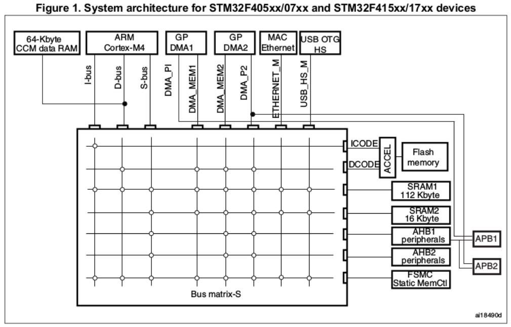
- f407 arch.JPG (88.55 KiB) Viewed 353 times
——–
my thoughts about sram management is that malloc (i.e. dynamic memory allocation) would take a more significant role, as this time round we may run more complex apps on the platform given its advantages. a simple example is we can setup ethernet, setup a tcp/ip stack and run a web server on the f4
https://stm32f4-discovery.net/2015/02/e … d-sd-card/
all the web server operations are not really dma intensive but certainly they are memory hungry, they may need to keep state of each connection e.g. store cookies, keep large or many structures in the heap etc. and the memory is only relieved if the user disconnect the session or a timeout is reached. i think similar things happen in the tcp/ip stacks as well as tcp allows half/closed connections and each tcp connection keeps state, so if there are a lot of tcp connections, 128 + 64k would easily run out
hence my thoughts are something like this, there can be malloc() which allocate memory in both the 128k (setting aside a reserve for dma – note that this could be smaller than a fixed sized reserve we set for dma in ldscripts) and 64k ccm but that all those shared 128k memory can be allocated via malloc_dma().
in that case you can literally use a big fraction of that 128k for dma if you deem fit. in addition, for this scheme, malloc() with no preference can give priority to ccm memory i.e. no dma, while malloc_dma() would always allocate in the first 128k, this would allow more intensive use of memory so that apps could use up most of that memory if necessary and still run.
this would certainly ‘help more applications run’ where otherwise in a fragmented (i.e. reserved) model fixed small blocks of memory allocated for dma would not be reallocated as general purpose memory. the fragmentation may hence cause apps to fail in memory tight situations (and there may still be pockets of available memory but won’t be allocated as they are reserved for a specific purpose e.g. dma)
note that this ‘web server’ scenario brings about a lot of new possibilities compared to the f1, i.e. you could literally control or configure every pin, do analog reads, send that over ethernet, configure afio, remote control (say an icd or camera) – e.g. stream video ‘on the web’
but all these are memory hungry apps. not necessarily cpu or io intensive
just 2 cents
Yes, I can try to check that out.
EDIT: I compared bxCAN section from F1 and F4 pdf and they seem to be exactly the same. So that’s good news
Nice. Check if the registers are at the same base address. I have noticed between series some devices have the same registers, but they are not at the same address. If not, you will need to edit the base address for the F4, and also confirm if all the registers are in the exact same order, just in case something changes on that too, like 1 register added or removed between both of them.
Maybe a stack could be placed into CCM. Maybe DSP/FPU based routines can utilize CCM better.. Quite complex stuff.. Needs future investigation.. Long way to go..
Interesting reading on internals related to ram arch http://cliffle.com/article/2015/06/11/matrix/
http://cliffle.com/project/glitch-demo/
For F103 interrupt for USB and CAN is shared. But I would guess that F4 has more interrupts available and they are not shared. Meaning USB Serial can be used together with CAN peripheral.
I have also observed that the F4 folder structure is much simpler than the F1 one. But I would keep it this way, as simply as possible.
So please do not copy/merge blindly all the files from F1, only those which are really needed.
EDIT
I am currently evaluating the USB mass storage class, then maybe even combined with CDC serial.
For that I have downloaded the latest official stm32_f105-07_f2_f4_usb-host-device_lib. This contains some new files compared to those already existing ones. I am just “fighting” with a lot of defines… ![]()
It’s taking me quite a while that way, but hopefully at the end I will have brought up a bunch of corrections andnew features from the newer files without breaking anything.
There is a few non-critical files that need more time, like the timers, there are many changes that look like bug corrections, but I need to get the reference manual open at the same time and confirm the registers and bits.
I am not touching anything related to USB and serial USB and I suspected you would be making more changes in that side, so no problem with any change on that.
Could someone explain what does the ‘line_num’ means and how can I check that for F4.
EDIT: does line_num mean bit in clock enable register ?
Bit 25 CAN1EN: CAN1 clock enable

Set and cleared by software.

0: CAN1 clock disabled

1: CAN1 clock enabled
I took the latest F1 core we use, which was based on almost the latest libmaple plus multiple additions and corrections over the year, and merged the F2/F4 files from libmaple, some of which were missing in the F1 folders. I added the USB files as per Steve’s repo just making a couple of small changes due to different names in the F1 core, and everything is compiling now, and I get blinking.
I believe the USB works, but found out my board is a POS and the usb port is only for power, so I will try to find my usb to serial converter and at least test the USART.
The F1 core has many additions and corrections over the Aeroquad F4 core, while 99% compatible, so I think it will be a better one to build upon.
It’s also more compatible with the F1 core, which hopefully will allow anyone working in the F1 core find the equivalent functions in the F4 one more easily.
I’ll try to post it in github so anyone can test and compare with the current F4 one and see if it works better or worse.
Code sizes are very similar. RAM use is lower since among the changes brought over was relocating pinmap to flash.
I’m also thinking on moving all core RAM structures to CCM, including the NVIC table since that would reduce latency over flash or shared RAM access.
Let me know where i can get from and test your changes.
Found out that RCC_AFIO is commented out in F1 and it is needed by CAN driver. Can we add it ? Luckily the IRQ for CAN1 is the same for F1 and F4
Solved..
Found out that RCC_AFIO is commented out in F1 and it is needed by CAN driver. Can we add it ? Luckily the IRQ for CAN1 is the same for F1 and F4
Tried with 460k and 920k speeds with no luck.
If someone has a board with a valid USB, please test and let me know if USB works.
1. downloaded victor’s Updated_STM32F4_master
2. used Generic STM32F407V Series
3. used HardFPU w/ hard calls
4. compiled and flashed – no go – nothing in terminal..
The version with old Discovery works.
PS:I removed the pin manipulation with LEDs in ag123’s Whetstone
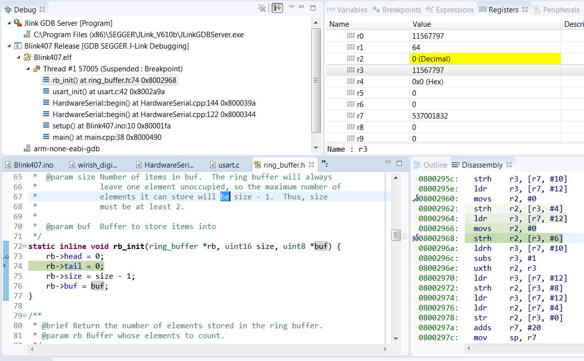
While debugging it crashes into reservedexception9 at:
*  @param buf  Buffer to store items into

*/

static inline void rb_init(ring_buffer *rb, uint16 size, uint8 *buf) {

rb->head = 0;

rb->tail = 0;

rb->size = size - 1;

rb->buf = buf;

}
-Os, -g, eabi-4.8.3-2014q1, HardFPU w/ hard, Generic STM32F4V Series, 168MHz clock
Beginning Whetstone benchmark at 168 MHz ...
Loops:1000, Iterations:10, Duration:8592.81 millisec

C Converted Single Precision Whetstones:116.38 mflops
It is ok, as the new Generic 407V does not posses such pins. We need the Z variant for that then..
#define CYCLES_PER_MICROSECOND  240    // F_CPU in MHz

// Note: Xtal frequency 8MHz

#ifndef BOARD_PLL_M

#define BOARD_PLL_M 4      // Xtal divider

#endif

#ifndef BOARD_PLL_N

#define BOARD_PLL_N 240    // PLL_Freq multiplier, PLL_Freq = Xtal / PLL_M * PLL_N

#endif

#ifndef BOARD_PLL_P

#define BOARD_PLL_P 2      // PLL_Freq post divider, F_CPU = PLL_Freq / PLL_P

#endif

#ifndef BOARD_PLL_Q

#define BOARD_PLL_Q 10     // USB divider = PLL_Freq / 48

#endif

..overclock did give a nice boost of some 50% it seemed, but the mflops seem a little lower than is possible
http://www.stm32duino.com/viewtopic.php … 150#p26867
perhaps it is due to the SerialUSB interrupts
With Serial it could be higher, but Serial does not work here yet..
– I will test USB serial with Victor’s new core.
– I will test Hardware serial (Serialx, x>=1) with speeds 115kbps and above – as Pito reported that it did not work.
– I am currently evaluating the GPIOs by driving a 16 bit parallel display – already detected some bugs.
– Next step will be the FSMC as it is the next logical step for driving parallel data bus displays – will do it instead of Pito, if it is OK.
EDIT
A question:
– what is the reason behind naming some core/system files to *_f4.*? The whole directory is anyway relevant only for F4, so it seems superfluous.
#define CYCLES_PER_MICROSECOND  240    // F_CPU in MHz

// Note: Xtal frequency 8MHz

#ifndef BOARD_PLL_M

#define BOARD_PLL_M 4      // Xtal divider

#endif

#ifndef BOARD_PLL_N

#define BOARD_PLL_N 240    // PLL_Freq multiplier, PLL_Freq = Xtal / PLL_M * PLL_N

#endif

#ifndef BOARD_PLL_P

#define BOARD_PLL_P 2      // PLL_Freq post divider, F_CPU = PLL_Freq / PLL_P

#endif

#ifndef BOARD_PLL_Q

#define BOARD_PLL_Q 10     // USB divider = PLL_Freq / 48

#endif

..i think Serial is literally mapped to SerialUSB on the F1 core, i’m thinking if we should keep it the same.
i think Serial is literally mapped to SerialUSB on the F1 core, i’m thinking if we should keep it the same.
#ifdef SERIAL_USB

#include <usb_serial.h>

#define Serial SerialUSB

#else

#define Serial Serial1

#endif
warning: undefined reference to `Serial1'#ifdef SERIAL_USB
#include <usb_serial.h>
#define Serial SerialUSB
#else
#define Serial Serial1
#endif
however, if the user choose to undef SERIAL_USB (say in platforms.txt), no usb initialization/enumeration would take place.
the sketch can then fill in the usb initialization / enumeration and work as a different usb device class e.g. usb mass storage, usb audio, usb cdc, usb cdc ethernet etc etc. i’d think this may be considered ‘advanced’ usage but i think those would really make these boards useful as a multi-purpose usb device.
then for the ‘basic’ usage e.g. SERIAL_USB is defined, we could make it ‘work like arduino uno’ hence sketches that are looking for Serial being pre-defined would find it. this may help in many cases as i’d think a lot of sketches which uses a serial console expect Serial to be simply there.
while normally it is simply a find and replace, in sketches that reference/use Serial, the references may literally be littered in ‘all over the sketch’
e.g. the sketch literally play the role of a shell and interprets commands, or for that matter Serial is used as basically the default serial interface interpreting commands from the host and sending data back
i’d guess these Serial usage could be pretty common in sketches
just 2 cents
I need to keep them in the same folders to track some more changes, then we can reorganize in a way that makes more sense. To me would be something like:
Leave common files in core and libmaple.
Take MCU specific files together to a single folder, named the cpu series.
Since they are in their own folder, take _f4 _f1 etc out of their names.
Simplify the structure in libmaple folder, too many subfolders.
There is the -archive flag issue with combiner recipe on Sloeber, however.
1. while building I get warning: undefined reference to `Serial’
2. while debugging it crashes at addr 8002968 (or 2962)
3. it seems to me the ring_buffer or buf structures are not set properly, or something like that.
- Serial 407 VP issue.JPG (177.18 KiB) Viewed 453 times
1. while building I get warning: undefined reference to `Serial’
2. while debugging it crashes at addr 8002968 (or 2962)
3. it seems to me the ringbuffer or buf is not set properly, or something like that.
Serial 407 VP issue.JPG
for openocd i used the binaries from gnu-arm-eclipse
http://gnuarmeclipse.github.io/openocd/install/
note that i’m using linux though
i think it is possible to connect via the j-link dongle via openocd as well
Do you follow my guide?
0. Prerequisites: Jlink debugger (any black or gray box
https://www.segger.com/downloads/jlink
J-Flash works identically as the ST-Link utility, so you may verify..
This is the front view at the Jlink box.
Jlink header.JPG
Jlink header.JPG (22.89 KiB) Viewed 97 times
Except the SWDIO and SWDCLK and GND you must connect VCC(1) to 3.3V (it does not power the chip but detects the chip’s voltage only)!
Your board must be powered.
I connected the RESET(15) too..
1. Install the latest nightly build of Sloeber IDE from:
https://oss.sonatype.org/content/reposi … -SNAPSHOT/
2. Update Sloeber and install Segger’s Jlink plugin, GNU GDB and Packs support plugin (and others..) via “Install new software” into the Sloeber from:
http://eclipse.baeyens.it/update/V4/nightly
3. Install Packs Manger for STM32F103 (or others when needed):
http://gnuarmeclipse.github.io/plugins/packs-manager/
EDIT: I have to install the Packs manager from http://gnuarmeclipse.sourceforge.net/updates-test in order to get STM32F407 added
EDIT: While installing latest MCU packages install the latest (ie 2.11.0 for F407).
4. Configure the project and debug environment (select STM32F103 in Setting>Devices):
http://gnuarmeclipse.github.io/debug/jlink/
Note: the guide tells you you have to start JLinkGDBServerCL.exe, here it works with JLinkGDBServer.exe
5. Here I have to start the jlink gdb server manually as External tool first (add the “Jlink GDB Server” into “External tools configuration”). When the Jlink GDB Server apps starts, just click ok. Only after that I click on my debug_project under the Bug Icon.. (what is the trick to get it running according to the books??).
The “Start Jlink GDB server locally” is disabled here (Debug configuration).
6. When the package for stm32f103 is installed in Sloeber you may mess with peripherals as the package includes the F103 .SVD file with registers’ and peripheral’s defs for you:
http://gnuarmeclipse.github.io/debug/pe … registers/
Do you follow my guide?
..
1. Install the latest nightly build of Sloeber IDE from:
https://oss.sonatype.org/content/reposi … -SNAPSHOT/
2. Update Sloeber and install Segger’s Jlink plugin, GNU GDB and Packs support plugin (and others..) via “Install new software” into the Sloeber from:
http://eclipse.baeyens.it/update/V4/nightly
3. Install Packs Manger for STM32F103 (or others when needed):
http://gnuarmeclipse.github.io/plugins/packs-manager/
EDIT: I have to install the Packs manager from http://gnuarmeclipse.sourceforge.net/updates-test in order to get STM32F407 added
EDIT: While installing latest MCU packages install the latest (ie 2.11.0 for F407).
4. Configure the project and debug environment (select STM32F103 in Setting>Devices):
http://gnuarmeclipse.github.io/debug/jlink/
Note: the guide tells you you have to start JLinkGDBServerCL.exe, here it works with JLinkGDBServer.exe
5. Here I have to start the jlink gdb server manually as External tool first (add the “Jlink GDB Server” into “External tools configuration”). When the Jlink GDB Server apps starts, just click ok. Only after that I click on my debug_project under the Bug Icon.. (what is the trick to get it running according to the books??).
The “Start Jlink GDB server locally” is disabled here (Debug configuration).
6. When the package for stm32f103 is installed in Sloeber you may mess with peripherals as the package includes the F103 .SVD file with registers’ and peripheral’s defs for you:
http://gnuarmeclipse.github.io/debug/pe … registers/
And yes it took me a week to master the stuff, but now it works as advertised (except the starting the Jlink Server has to be done manually here via External Tools.).
Now let’s see if I can complete the rest of the steps without messing it up again, unlikely
but working on danieleff and stm cores could really save resources and efforts as my guess is that as we progress on building the cores, we’d do similar things like trying to make the same code base work across the different series (e.g. f1, f2, f3, f4, f7 etc)
developing it this way targetting the f4 may however let us target certain soc (e.g. f4) features and the combined board features or perhaps implement some features differently. e.g. how we are working with ccm now may not be quite the same as how a hal based core does it. e.g. hal based core may use ccm differently to maintain compatibility across series. e.g. we may prioritise ccm usage vs the shared 128k while a default configuration in perhaps hal core may first use the shared 128k and subsequently use ccm after the shared 128k runs out
just 2 cents
e.g. on the f4 with the somewhat larger ram, it is pretty feasible to run a micro (windows) gui while doing all other things adc, dac, spi etc that’s done on f1. while in the f1 20k would easily run out for ‘ram intensive’ usage like a windows style gui
actually for f4 192k isn’t truly a very generous amount of ram, but it would many allow more apps to work where it otherwise couldn’t
e.g. apps like micropython and elua mainly targets platforms like f4 due to the combined features of more ram, flash and a faster cpu (intepreted languages do have overheads)
Me, I have to first try it, too.
A very first look into those sources on github shows an apparently logical structure.
And I have to agree that for F4 that approach would give more value and faster development times than the libmaple based one.
Also providing marginal compatibility with mbed.
Meaning, I think we all can conclude at the moment:
the “libmaple based” implementation will not be continued.
Let’s switch to Daniel’s track and concentrate all our forces in one direction (hopefully Daniel will welcome this decision ![]() )
)
Me, however, I will still continue to use Arduino_STM32 (Roger’s repo) for F1.
And I think we can use it as basis to improve performance of some peripherals (USB serial, SPI, hardware serial,…) for F4.
Is there something specific what libmaple can do and STM HAL can’t??
oh & for f4, 1’d need to get an f4 with the ART accelerator (500 mflops psuedo whetstone benchmark @240mhz) at least, that’d cope with all the codes however fat it may be, if u get an stm32f405rgt6 it is 1 m flash, for once we see the m suffix for flash ![]()
I will update the first post on this thread to declare that until we find an advantage in the libmaple F4 core over the HAL, we consider this thread dead and the focus will be on Daniel’s and perhaps the STM cores, as they also use the HAL so drivers should be compatible between the two to a high degree.
#include <usb_serial.h>
void checkcmd(void);
//note this is for the black f407vet6 board

int ledPin = BOARD_LED_PIN; //PA6

int led1 = BOARD_LED2_PIN; //PA7
int print = false;
// the setup() method runs once when the sketch starts

void setup() {
SerialUSB.begin(0);
//initialize the digital pin as an output:

pinMode(ledPin, OUTPUT);

pinMode(led1, OUTPUT);

digitalWrite(ledPin, HIGH);

}
//the loop() method runs over and over again,

//as long as maple has power

void loop() {

int i;

for (i = 0; i < 10; i++) {

digitalWrite(ledPin, HIGH);

delay(100);

digitalWrite(ledPin, LOW);

delay(100);

}

checkcmd();

if (print) SerialUSB.println("Hello world F407");

for (i = 0; i < 5; i++) {

digitalWrite(ledPin, HIGH);

delay(500);

digitalWrite(ledPin, LOW);

delay(500);

if (print) SerialUSB.println("Hello world F407");

checkcmd();

}

}
// listen for the keys 'p' print or 's' stop from the usb serial console

void checkcmd() {

char r;

if(SerialUSB.available()) {

r = SerialUSB.read();

} else

return;
if(r=='p') { //print

print = true;

} else if (r=='s') { //stop

print = false;

}

}
If you want to use libmaple core with F4 generic board, please follow this thread:
http://www.stm32duino.com/viewtopic.php?f=39&t=1976
Btw, instead of SerialUSB simply use Serial.

