if anyone spots a schematic or any other info, please let me know?
pics are on the wiki
the vet6’s arrived this morning from
https://www.aliexpress.com/item/Free-sh … 22721.html
@ £9.15
awaiting the zet6’s from
https://www.aliexpress.com/item/Free-sh … .64.4hrwhV
@ £11.43
sadly an addicted
stephen
The price of the F7 boards is now not much higher then the F4
I know we dont have a core for the F7 at the moment, but as various people are looking at cores to support a wider range of devices, I think sooner or later F7 will get some support.
( at the moment you could probably build a HAL MX F7 core )
i spot a 103vg, the following caught my attention
2-way FSMC bus leads, you can access TFT / DM9000 network module, the restaurant has a compatible module
seems it has the fsmc broken out twice, they quote having a display whilst debugging a network interface
bar that no f7’s at all. doing a search yields 10 off for £530 and a single at $56, about 6%??
and of course discovery with STM32F746G or STM32F746NG, farnell have the same pdf for each.
so what the differences are ??
waveshare.com only their STM32F746IGT6, all 3 levels $60/$130/$150, the last 2 having 4.2″/7″/10″ lcd available
the discovery disco with STM32F746NGH6 is $71 with a 4.2 display
stephen
stop making me drool
i’d rather plug into the motherboard, seems neater and probably less prone to errors in counting pins or reading pin label through a maze of wires.
back to original board, there is a schematic of their stm32f103/f107 with nrf24 around, tf card is probably sdio, tft needs to be measured just to find supplies and look for possible matching interface displays.
spi flash? on which?
rtc battery is supplied, 32khz crystal is there, where’s/what”s standard for an rtc?
my boards don’t usually end up in a box ( of their own with psu etc ) ![]()
the waveshare wiki is quite a good source of info, not sure if the code is SPL or HAL.
by now most likely a mixture.
the last cdrom in a package from them had a cube hal file. wrong one though.
sent an email suggesting they could include the full set, reply suggested copyright worries.
all of them probably exceeds a reasonable portion as with book excerpts.
still a best subset of f1, f4 & f7 would provide for most boards?
adding SPL to those being even better.
stephen
a bit of browsing later
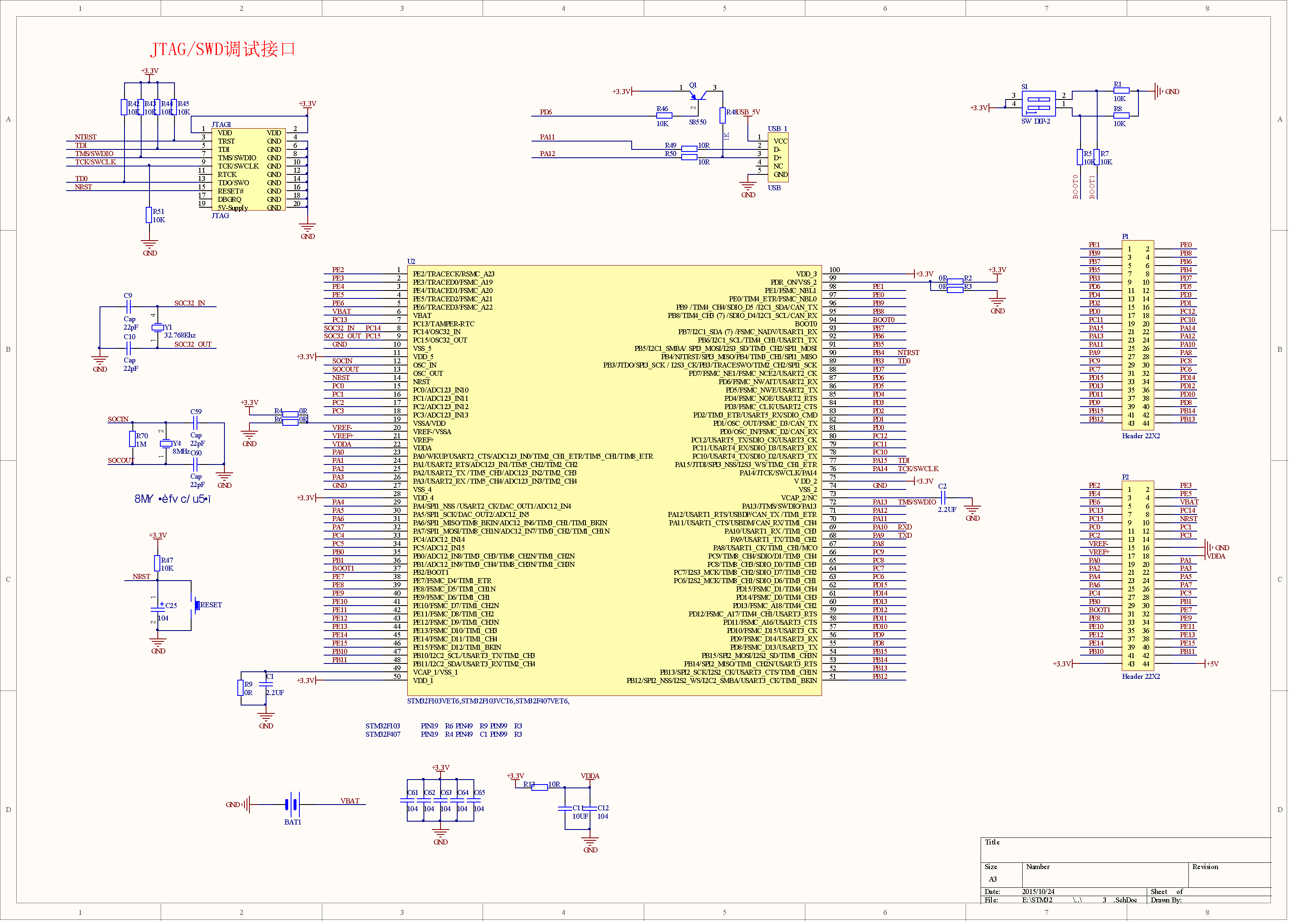
http://www.dragonwake.com/download/down … T6_sch.pdf
no vet6 schematic though ![]()
stephen
Unfortunately I cannot find any tutorial, or guide to fire it up. If I connect the board via USB Windows 7 says Unknown USB device, and nothing happens.
Does somebody have a quickstart guide on these boards? I would appreciate it.


http://www.csun.co.jp/SHOP/2015120201.html
actually it was the site one. a search on f407 returns this board, click etc
then about a third down is a set of 4 links, sch, datasheet, ???? and an examples manual
if you go roaming with stm32f1on search or f42 or cortex m3 or arm from the side links, there’s a fair bit of info.
pretty sure i’ve seen the pcb ‘blotch’ last night/v early am – j4 is top edge & 2/3 across, also the sch
stephen

Sep 14 19:36:00 i70 kernel: [32545.249005] usb 1-1.1.3: new full-speed USB device number 17 using ehci-pci

Sep 14 19:36:00 i70 kernel: [32545.321028] usb 1-1.1.3: device descriptor read/64, error -32

Sep 14 19:36:01 i70 kernel: [32545.497111] usb 1-1.1.3: device descriptor read/64, error -32

Sep 14 19:36:01 i70 kernel: [32545.673202] usb 1-1.1.3: new full-speed USB device number 18 using ehci-pci

Sep 14 19:36:01 i70 kernel: [32545.745228] usb 1-1.1.3: device descriptor read/64, error -32

Sep 14 19:36:01 i70 kernel: [32545.921300] usb 1-1.1.3: device descriptor read/64, error -32

Sep 14 19:36:01 i70 kernel: [32546.097396] usb 1-1.1.3: new full-speed USB device number 19 using ehci-pci

Sep 14 19:36:02 i70 kernel: [32546.505578] usb 1-1.1.3: device not accepting address 19, error -32

Sep 14 19:36:02 i70 kernel: [32546.577628] usb 1-1.1.3: new full-speed USB device number 20 using ehci-pci

Sep 14 19:36:02 i70 kernel: [32546.985811] usb 1-1.1.3: device not accepting address 20, error -32

Sep 14 19:36:02 i70 kernel: [32546.985950] usb 1-1.1-port3: unable to enumerate USB device
In other words… remember the golden rule… always check your voltages.
notice of another 2 parcel behind door on return 2:20pm.
oh, apparently the colour of motherboard sata sockets means something? ![]()
stephen
oh, apparently the colour of motherboard sata sockets means something?
stephen
is the process detailed anywhere? might be useful if someone could do that?
most of mine v & z, mainly e’s, maybe a g as well.
stephen
<edit>
in the meantime and in the context of boards.txt and platform.txt. please tell me ## or # are comment lines and backslash continues on the next
<\edit>
I cant DFU to it via USB and it takes 3 reset attempts before it appears on USB at all as a DFU device.
I will try uploading via STLink and then see whether USB works for USB serial
i started by copying the discovery entry, along with bits from f1 files for variants and menu hints.
i’ll probably switch and start again, but do the same with the bits of f1 files.
##########################
i may have asked this else where, are # & ## comments and continuation line follows is a backslash (\) ?
me being lazy for print, on second thoughts, that’s landscape. still interested in confirmation though.
i had 4 instances of cutecom and 3 usb/uart blocks attached to rx3/tx1 / rx3/tx2 / rx3/tx3 running the other night, had output on 3 out of 4, braincell has failed to retain particulars of which was what ![]() two were the same so i suspect the 232 usb was off a9/a10
two were the same so i suspect the 232 usb was off a9/a10
it was a different board.
not sure if that helps
stephen
I think one is a 24c02 eeprom and the other is a W25X16 (not sure what that is)
I think one is a 24c02 eeprom and the other is a W25X16 (not sure what that is)
Shame neither device is actually fitted ![]()
https://www.aliexpress.com/item/STM32F4 … 12486.html
The connectors are black in my case, even when the image shows yellow connectors.
Thats exactly the same as mine, I bought it from the same people and my connectors are black as well
The pin headers were not soldered on, though they were fitted. I have now soldered them on, as it will make testing easier, but I can see for real projects its better to solder wires directly to the holes
I compiled using the STM32 Discovery F407 board and then flashed using STLink
I’ve updated the repo yesterday as I had issue with STLink not working
Serial USB seems to be defined for that board, but Serial.begin() is not called in the init functions, so you have to call it yourself in setup() etc if you want enable serial usb.
I also added another windows driver bat file to install the driver for the VID/PID pair that seems to be used by the F4 core (not sure why it doesnt use the Leaflabs ID’s)
I still have not got DFU uploading to work
I think there may be an issue with the USB enumeration PNP transistor miss firing when its not supposed to. I think they should have include a pull up resistor (albeit a weak on) on its base to prevent it conducting, but I can’t be sure thats the problem
- STM32F103VET6,STM32F103VCT6,STM32F407VET6VGT6_Page_1.png (162.54 KiB) Viewed 632 times
where did you find those?
i think i had bad blurry sheet1 from my source, requested if there was indeed a 2nd sheet could he send it – nada, zip, zilch
any ideas on translating a japanese pdf ? suspect same as here
stephen
There should not be any resistors on USB lines because the OTG USB Phy does this according to the manual. The board has a Pull up on DM (PA12) and 22R on PA11 and PA12. I don’t think 22R should matter but, pull up on DM will.
Any suggestions? (I’m thinking of removing the resistor see if this makes it work)
EDIT:
-Found the issue, If VUSB is not connected DM needs a pull up
– STM32 code needs to be edited to disable VUSB sense.
STM32Cube_FW_F4_V1.14.0/Drivers/STM32F4xx_HAL_Driver/Src/stm32f4xx_ll_usb.c
HAL_StatusTypeDef USB_DevInit (USB_OTG_GlobalTypeDef *USBx, USB_OTG_CfgTypeDef cfg)
{
….
// FIX USBx->GCCFG |= USB_OTG_GCCFG_VBUSBSEN;
stephen
Even if you manage to get it to enumerate as a DFU device, its a pain to uploads as the version of DFU in the F407 doesnt seem to work well with the normal dfu-util implementation on Windows.
I found only STM’s own DFU driver and DSUSe program would communicate with the DFU bootloader in the MCU
So I gave up using DFU and connected a STLink for uploads
Once I did that, I can get the board to appear as USB Serial, so I don’t think it was a hardware issue, but just the DFU implementation inside the F407
If I get time I was intending to write a USB Bootloader for the F407, but at the moment it looks like I won’t have any free time for many months to come, so I’m not likely to have time to write it ;-(
I bougth this STM32F407VET6 board off AliExpress.
I’m trying to upload sketches to it using a Baite ST-link v2.
First step is just a blink program. How ever, even though I use PB9 as output, I’m not seeing anything happening on the board itself.
This is the verbose output from the compilation and upload:
Sketch uses 15900 bytes (1%) of program storage space. Maximum is 1048576 bytes.

Global variables use 13504 bytes of dynamic memory.

STM32 ST-LINK CLI v2.1.0

STM32 ST-LINK Command Line Interface
ST-LINK SN : 53FF6D065178535442162387
ST-LINK Firmware version : V2J27S6
Connected via SWD.
SWD Frequency = 1800K.
Connection mode : Normal.
Device ID:0x413
Device flash Size : 512 Kbytes
Device family :STM32F40xx/F41xx
Loading file...
Flash Programming:
File : C:\Users\Martin\AppData\Local\Temp\arduino_build_791695\F4Blink.ino.bin
Address : 0x08000000
Flash memory programming...
±±±±±±±±±±±±±±±±±±±±±±±±±±±±±±±±±±±±±±±±±±±±±±±±±± 0%
0%ÛÛÛÛÛÛÛÛÛÛÛÛÛÛÛÛÛÛÛÛÛÛÛÛÛÛÛÛÛÛÛÛÛÛÛÛÛÛÛÛÛÛÛÛÛÛÛÛÛÛ 100%
Flash memory programmed in 0s and 922ms.
Programming Complete.
MCU Reset.
Application started.
Invalid version found: 1.04
Invalid version found: 1.04
Not sure if it’s the stm32duino version or not.
After connecting the USB it installed the driver e:automatically, and it is showing 2 new removable storages E: and K:, device description SD flash disk, manufacturer ALIENTEC
Schematics and pcb: my revision is v3.0, and the schematics and pcb layout seems to be the third one
The schematics could be the one from the .pdf in this thread, the pcb layout differs.

- 407ZET6_v30.jpg (40.46 KiB) Viewed 817 times
After connecting the USB it installed the driver, and it is showing 2 new removable storages E: and K:, device description SD flash disk, manufacturer ALIENTEC
PS: the schematics and pcb layout on the wiki is from board rev v1.0 or 2.0. So we need to dig for the 3.0 then.
USB\VID_0483&PID_5720&REV_0200
http://www.ebay.com/itm/Core407V-STM32F … 2124645773
havn’t really tried it out, but if everything works, it is really good value
it’d looks like this group here almost ‘monopolise’ those boards ![]()
Not ready to pull yet, but I’m happy to upload what i have to github, so that we can all come to a common pinmap, etc.
their name is rather similar to a Waveshare product
as to a monopoly on it and its big brother within this group, buy a couple and make the most of it; i think the price is only likely to rise.
stephen
@palmerr, a github link would be nice, so that parallel work would be possible.
their name is rather similar to a Waveshare product
as to a monopoly on it and its big brother within this group, buy a couple and make the most of it; i think the price is only likely to rise.
stephen
so has anyone seen linux or similar on one of these or is not enough ommf for that?
srp
srp
These boards are still far from rpi/bb stuff (most notable in performance, MMU, access to external RAM).
These F407 mcus lack mmu, so you cannot run linux on it. There is a uClinux which runs on mmu-less cpus, with some limitations. You need at least 16MB of RAM, afik.
The closest fit could be the F429 (as it possess SDRAM controller) running the uClinux:
Though ,quite a few decades ago, I did port MINIX onto a 96KB machine ( baby IBM 360) running at 16 MHz. Command line only, of course. We are a little spoilt these days with GHz, muliti-CPU chips available for tens of $.
http://www.emcraft.com/products/343
that’s my usual expectation of Linux whenever i get something that does not seem to work with Linux.
i think i already knew about the mmu aspect though, just an odd thought.
back to the black V, anyone traced/avo’ed the FLASH_CS line ? schematic has one place and PA4 is not labelled, but PB0 is as F_CS
SPI1 seems to be on PB3, PB4 and PB5, afio strikes.
ok, where in the arduino_stm32 land is the low level initial setup of the various peripherals – clks, i2c, spi etc performed?
stephen
so has anyone seen linux or similar on one of these or is not enough ommf for that?
srp
There is for example LiteBSD unix running on the pic32MZ (512kB ram on chip). Or RetroBSD unix running on pic32MX (128kB ram on chip).
There is for example LiteBSD unix running on the pic32MZ (512kB ram on chip). Or RetroBSD unix running on pic32MX (128kB ram on chip).
https://www.youtube.com/watch?v=TJWeVvicvZk
i think they are available on the stm32f407 socs
i’d think these could leave for ‘future’ enhancements in the developments, i’m not sure just how much that’s going to help spi based lcds as i’d imagine that spi or even the lcd (controller) itself may be a bottleneck
<edit>oh i so hoped it did
I hope this is the appropriate topic for the following question:
How can I compile for these processors using the full RAM size?
I have boards with both of these processors.
I use “STM32 Discovery F407” of the STM32duino.com package to compile and download using ST-Link.
Now I need more than the 128k RAM for e-paper buffer size (800×480 x 4 gray level).
Where can I specify the 192k RAM size to the linker? I assume I can clone the “STM32 Discovery F407” in boards.txt
The boards I use are:
http://www.buy-lcd.com/index.php?route= … t_id=22833
https://www.aliexpress.com/store/produc … 62341.html
https://www.aliexpress.com/store/produc … 22721.html
Thank you for your help
Jean-Marc Zingg
But actually you only need 800x480x2 (2bits for up to 4 gray levels) = 96kB memory, which would fit into the “normal” 128kB area.
The linker shall care on the memory segments distribution such they fit accordingly.
Of course 96kB buffer cannot be placed into the CCM (64kB), even a part of it, but the linker can place that 96kB buffer into RAM and the other stuff to the CCM, mind there are several limitations when using the CCM.
In addition to the 96k display buffer there are the 14k taken for an empty (new) Arduino program,
plus two “wave tables” of ~10k, plus some more overhead, unfortunately.
And the final goal would be 1024×786.
So I have to start with b/w only buffer.
Do you have a link to some easy explanation of the two RAM regions, and maybe even how to use them with the Arduino IDE?
Thank you very much!
#define GxGDE035A3_WIDTH 800

#define GxGDE035A3_HEIGHT (480 - 51)

#define GxGDE035A3_BUFFER_SIZE GxGDE035A3_WIDTH * GxGDE035A3_HEIGHT / 4 // 2bits per pixel
Arduino: 1.8.2 (Windows 10), Board: "STM32 Discovery F407"
c:/users/zinggj/appdata/local/arduino15/packages/stm32/tools/arm-none-eabi-gcc/4.8.3-2014q1/bin/../lib/gcc/arm-none-eabi/4.8.3/../../../../arm-none-eabi/bin/ld.exe: C:\Users\ZinggJ\AppData\Local\Temp\arduino_build_825677/DESTM32-L_V4.ino.elf section `.bss' will not fit in region `ram'
c:/users/zinggj/appdata/local/arduino15/packages/stm32/tools/arm-none-eabi-gcc/4.8.3-2014q1/bin/../lib/gcc/arm-none-eabi/4.8.3/../../../../arm-none-eabi/bin/ld.exe: region `ram' overflowed by 248 bytes
collect2.exe: error: ld returned 1 exit status
exit status 1
Error compiling for board STM32 Discovery F407.
This report would have more information with
"Show verbose output during compilation"
option enabled in File -> Preferences.
#define GxGDE035A3_WIDTH 800
#define GxGDE035A3_HEIGHT (480 - 52)
#define GxGDE035A3_BUFFER_SIZE GxGDE035A3_WIDTH * GxGDE035A3_HEIGHT / 4 // 2bits per pixel
Arduino: 1.8.2 (Windows 10), Board: "STM32 Discovery F407"
c:/users/zinggj/appdata/local/arduino15/packages/stm32/tools/arm-none-eabi-gcc/4.8.3-2014q1/bin/../lib/gcc/arm-none-eabi/4.8.3/../../../../arm-none-eabi/bin/ld.exe: C:\Users\ZinggJ\AppData\Local\Temp\arduino_build_825677/DESTM32-L_V4.ino.elf section `.bss' will not fit in region `ram'
c:/users/zinggj/appdata/local/arduino15/packages/stm32/tools/arm-none-eabi-gcc/4.8.3-2014q1/bin/../lib/gcc/arm-none-eabi/4.8.3/../../../../arm-none-eabi/bin/ld.exe: region `ram' overflowed by 48 bytes
collect2.exe: error: ld returned 1 exit status
exit status 1
Error compiling for board STM32 Discovery F407.
This report would have more information with
"Show verbose output during compilation"
option enabled in File -> Preferences.
#define GxGDE035A3_WIDTH 800
#define GxGDE035A3_HEIGHT (480 - 53)
#define GxGDE035A3_BUFFER_SIZE GxGDE035A3_WIDTH * GxGDE035A3_HEIGHT / 4 // 2bits per pixel
Sketch uses 846208 bytes (80%) of program storage space. Maximum is 1048576 bytes.
Global variables use 114536 bytes of dynamic memory.
STM32 ST-LINK CLI v2.1.0
STM32 ST-LINK Command Line Interface
ST-LINK SN : 52FF6E065077575227540187
ST-LINK Firmware version : V2J27S6
Connected via SWD.
SWD Frequency = 1800K.
Connection mode : Normal.
Device ID:0x413
Device flash Size : 512 Kbytes
Device family :STM32F40xx/F41xx
Loading file...
Flash Programming:
File : C:\Users\ZinggJ\AppData\Local\Temp\arduino_build_825677\DESTM32-L_V4.ino.bin
Address : 0x08000000
Flash memory programming...
±±±±±±±±±±±±±±±±±±±±±±±±±±±±±±±±±±±±±±±±±±±±±±±±±± 0%
0%ÛÛÛÛÛÛÛ 15%ÛÛÛÛÛÛÛÛ 30%ÛÛÛÛÛÛÛ 45%ÛÛÛÛÛÛÛÛ 60%ÛÛÛÛÛÛÛ 75%ÛÛÛÛÛÛÛÛ 90%ÛÛÛÛÛ 100%
Flash memory programmed in 22s and 641ms.
Programming Complete.
MCU Reset.
Application started.
You may use an 8pin SPI external sram/fram/mram (up to 512kB/chip)..
Or you may add a 256kx16 sram provided you use a zet6 board.. Browse this forum..
You may use an 8pin SPI external sram/fram/mram (up to 512kB/chip)..
Or you may add a 256kx16 sram provided you use a zet6 board.. Browse this forum..
http://www.mouser.com/Semiconductors/Me … w8Z1z0vhtu
but of course this is just mbits, but i’d guess if 1 is determined, you may well find it and 1024×768 ‘full color’ screen buffer may not longer be simply a pipe dream
to go with lower costs SDRAM may be a good alternative with FSMC
http://www.ebay.com/sch/i.html?_from=R4 … m&_sacat=0
the biggest pipe dream is actually to do 1920×1680 HDMI full HD video and interface directly with HDMI, this my guess would remain a pipe dream for some time
![]()
How can the internal 64k RAM in addition to the internal 128k RAM of these processors be used by an Arduino program?
Why are 28k of the internal 128k RAM not available for an Arduino program (on these processors) ?
Jean-Marc Zingg
Arduino_Stm32duino
or
Arduino_core_Stm32
?
As you only posted parts of your variables, we cannot know anything about the rest of them.
Meaning a part of the the 28k is used by system variables (USB serial massively uses Ram), the rest is used by other variables of your program.
Arduino_Stm32duino
or
Arduino_core_Stm32
?
As you only posted parts of your variables, we cannot know anything about the rest of them.
Meaning a part of the the 28k is used by system variables (USB serial massively uses Ram), the rest is used by other variables of your program.
I think it should be 128K. (There is a 112K region directly followed by a 16K region)
To use the extra 64K:
1. jtag.ld: below the ram line, put `ccmram (rw): ORIGIN = 0x10000000, LENGTH = 64K`
2. common.inc: below .bss section, put
.ccmram (NOLOAD):

{

. = ALIGN(8);

*(.ccmram .ccmram.*)

} > ccmram
The demo code I converted from Keil5 to Arduino IDE STM32 even had a function Init_RAM, but this was empty.
So I will need to learn how to initialize FSMC to use that SRAM, as long as I use the demo board.
Is there a library example for FSMC RAM? or a post describing FSMC initialization?
(please post a link to the most relevant post, not the whole lengthy topic, thanks).
I still would like to know why not the full 128k can be used; can I avoid USB code?
Jean-Marc Zingg
I think it should be 128K. (There is a 112K region directly followed by a 16K region)
To use the extra 64K:
1. jtag.ld: below the ram line, put `ccmram (rw): ORIGIN = 0x10000000, LENGTH = 64K`
2. common.inc: below .bss section, put
.ccmram (NOLOAD):

{

. = ALIGN(8);

*(.ccmram .ccmram.*)

} > ccmram
Btw, you could eventually try the generic F4 branch of my repo, there is already the generic F407 board defined as variant, and also some optimizations done. A minimal sketch uses ~12kB RAM, wherein USB alone more than 4kB.
http://www.stm32duino.com/viewtopic.php?f=39&t=1976
Btw, you could eventually try the generic F4 branch of my repo, there is already the generic F407 board defined as variant, and also some optimizations done. A minimal sketch uses ~12kB RAM, wherein USB alone more than 4kB.
http://www.stm32duino.com/viewtopic.php?f=39&t=1976
Simply download from github and extract the files to the appropriate folders (delete any previous version before).
Simply download from github and extract the files to the appropriate folders (delete any previous version before).
This board starts up with 16 times slower speed, intermittently to almost every time.
I download code trough ST-Link. The board has no reset button, but I added a push button. Reset by push button seemed not to work, e.g. no serial output, and reset by ST-Link (MCU reset, Application started) intermittently started, but drawing on e-paper was very slow.
Most of the time startup was ok after the second or third download of the same code, but failed again sometimes after code change.
With bitmap buffer added, startup starts slow every time, even with reduced buffer size.
The measured clock output to the display seems to be exactly 16 times slower then.
The same code runs fine on a STM32F407VET6 board, but I can’t check with the e-paper display (no FCP connector, no e-paper specific supply voltages).
BOOT0 has 10k to GND, and I connected it directly to GND for test, BOOT1 has no connector, but seems to have 10k to GND.
Has anyone seen such a strange behavior?
Has anyone an explanation for this behavior? fall-back to the slow clock option of the processor?
Can I kick the processor clock in the setup function?
it works for:
Global variables use 36336 bytes of dynamic memory.
Check the MAP file for RAM limitations.
Btw, you could eventually try the generic F4 branch of my repo, there is already the generic F407 board defined as variant, and also some optimizations done. A minimal sketch uses ~12kB RAM, wherein USB alone more than 4kB.
http://www.stm32duino.com/viewtopic.php?f=39&t=1976
Check the MAP file for RAM limitations.
I tried with this version, but it seems the processors lost some ports and pins.
Can I disable USB support easily in the startup code?
http://www.ebay.com/itm/STM32F407VET6-S … 1950756099
http://www.ebay.com/itm/Cortex-M4-STM32 … 2713751397
zgt not seen
srp
[zmemw16 – Sun Aug 13, 2017 12:25 pm] –
the zet is remaining rather high at about $15
zgt not seen
srp
At that price, you might be tempted to go for a Pi Zero W instead of the ZET
it’s horses for courses, the zgt Devils Cross is rather nice for IO and pretty much sorted connectors wise, micro usb, micro sd and dupont leads, sadly no built in ethernet ![]()
stephen
[ahull – Mon Aug 14, 2017 9:42 am] –[zmemw16 – Sun Aug 13, 2017 12:25 pm] –
the zet is remaining rather high at about $15
zgt not seen
srpAt that price, you might be tempted to go for a Pi Zero W instead of the ZET
yup & if you don’t mind a ‘clone’ there’s orange pi for even less
https://www.ebay.com/sch/i.html?_sop=15 … =450&rt=nc
http://www.orangepi.org/orangepizero/
but without all that fancy adc, dac, fancy multiple spi, i2c and more gpio pins than do one can count with fingers + toes etc
![]()
srp
perhaps one day we may be able to pack an octoprint http://octoprint.org/ clone and do away with the host, send your g-code file, stm32f4* controller does all the rest (level bed, control temperature, control all the acceleration / deceleration (i.e. do *physics calc* f = ma, accelerate & extrude faster in a long stretch then slow down towards the end etc) and run the lcd show a fancy lcd with print progress, temperature etc with a fancy gui to to control pretty much all aspects of the print and on top of all that stream a video showing the print in progress sending it over wifi to your web browser
my guess is, the main limit as always is *memory*
one of those things that comes fairly close to that for now is beaglebone black + replicape
https://www.thing-printer.com/product/replicape/
as after all beaglebone black has the dram & storage to run a full linux distribution
![]()
Why can not I use AnalogRead ?
void setup() {
pinMode(PA0, INPUT);
Serial.begin(115200);
while (!Serial) {
delay(1);
}
}
void loop() {
delay(1000);
Serial.println(analogRead(PA0));
}
void setup() {
pinMode(PA0, INPUT);
Serial.begin(115200);
}
void loop() {
delay(1000);
Serial.println(analogRead(PA0));
}
As You wrote – also not working.
When reading the readings are always 0.
although the level is changed to PA0
If I put the library https://github.com/danieleff/STM32GENERIC – the same code is working fine.
What could be the problem ?
because PA0 is connected to user button on some boards… so default pull down I guess…
Or PA0 on f407 could be used for Uart4
Edit: Button could not explain why it works with Daniel Core….
I know a few people e.g. Martin and Steve continue to work with Libmaple F4, but IMHO it should be retired in favour of STMs core or STM32GENERIC
I hear You.
[lightcalamar – Mon Sep 25, 2017 8:14 am] –
Be error making libmaple work on F4xxx boards
What is that supposed to mean?
Libmaple works on generic black F4 board: http://stm32duino.com/viewtopic.php?f=39&t=1976
[stevestrong – Mon Sep 25, 2017 8:26 am] –
What is that supposed to mean?
Libmaple works on generic black F4 board: http://stm32duino.com/viewtopic.php?f=39&t=1976
I write again that it is a mistake to make that library work in F4xxx, slows down the CPU, then you choose whether or not to do that each one will use it. Also you do not need to use it, any device you make your library and it works without going through the maple
stm32generic and st’s core would likely be compatible across more mcus even including stm32f3 series due to its design and use of ST’s cube mx hal


