I am starting this topic because I think this board — which I will call the “STM32F407VGT6 development board” (see picture) — deserves a specific area on the forum. Clones are sold under several brand names from China — currently at £7.27 on eBay.
Although the STM32F4xxx MCUs are mentioned in plenty of snippets around this forum and other sites, I found it hard as a newcomer to get the overview and put the details in sequence to get started, especially for the Mac OSX environment. I will share here my tested outcomes to help others get started quicker and hope to have further discussions about projects using this board.
Why this processor?
• 168MHz clock (plus an additional 32MHz oscillator for the real-time clock)
• 1 Mbyte of Flash memory
• LCD parallel interface, 8080/6800 modes
• Low-power operation
• 3×12-bit, 2.4 MSPS A/D converters
• 2×12-bit D/A converters
• Up to 17 timers: up to twelve 16-bit and two 32- bit timers up to 168 MHz
• Serial wire debug (SWD) & JTAG interfaces
• Up to 77 I/O ports, all with interrupt capability (on this board)
• Up to 3 × I2C interfaces
• Up to 4 USARTs/2 UARTs (10.5 Mbit/s)
• Up to 3 SPIs (42 Mbits/s)
• 2 × CAN interfaces (2.0B Active)
• SDIO interface
• USB 2.0 full-speed device/host/OTG controller with on-chip PHY
• USB 2.0 high-speed/full-speed device/host/OTG controller
• 10/100 Ethernet MAC with dedicated DMA: supports IEEE 1588v2 hardware, MII/RMII
• True random number generator
In short, it knocks the spec for the Arduino Mega into a cocked hat!
The term “up to” means that these features cannot all be used at the same time due to the sharing of pins, but with a bit of planning most of them can. See the datasheet for details: https://www.st.com/resource/en/datasheet/dm00037051.pdf
Why this board?
I call it a “development board” because it has less on it that other “Discovery” boards, or STM’s own NUCLEO series; so instructions related to those boards are not usually applicable. It has the basics needed to make the processor work, and is in that sense comparable to Arduino boards or the Maple Mini for the STM32F1. It measures just 58mm x 45 mm — so bigger than the maple Mini or Arduino Micro, but still a little smaller than the Arduino Uno or Mega. It is therefore a good candidate for building into projects.
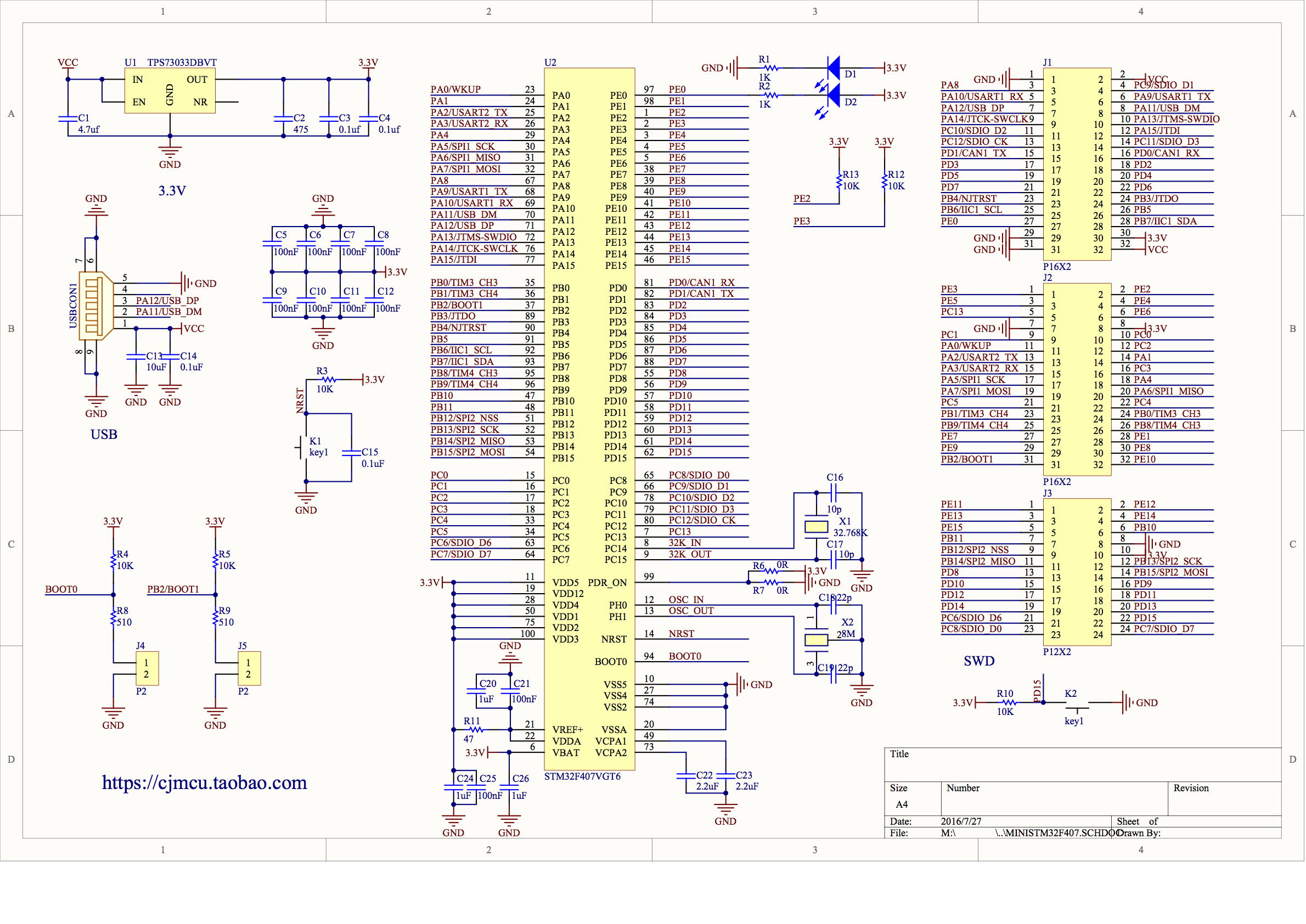
The processor on this board is the STM32F407VGT6 — i.e. the version with camera interface, Ethernet, 1Mb flash memory and LQFP-100 package. Besides the MCU chip, the board provides a micro USB port fully-connected to the on-chip USB interface (PA11, PA12) and can provide the power supply; a 5V to 3.3V regulator; two oscillators; two push-buttons (one ‘reset’, one for the user program); two LEDs (one for ‘power on’, one for the user program), and jumpers for Boot0 and Boot1. The schematic can be downloaded from http://dubstylee.net/v/wp-content/uploa … 07VGT6.png [Thanks to forum user ‘flodejr’ for this link].
In further posts, I will give validated instructions on how to upload a ‘blink’ program to this board from Arduino IDE on Mac OSX.
Watch this space… ![]()
The STM32F407VGT6 is supported should be supported in most of the cores (Rogers F4, genericCore, even with the official core it shouldn’t be a problem writing a new variant since the – quiet familiar – STM32F407VET6 is support (this “black board”)).
Compared to the “Black” VET board (without judgment) https://www.aliexpress.com/item/1PCS-ST … 4c4dDlaHFB
- Price is more or less equal
- RAM: 192 VET, 512VGT
- Flash: 512MB VET, 1024MB VGT
- 96 (24×4) (main) pinouts VET, 88(24×4 + 12×2) (main) pinouts VGT) – so are all periphery pins broke out on VGT? (has to be checked) + on VET: 5V output AND 3.3V
- 4 Buttons VET, 2 Buttons VGT
- VET with additional features: TF SD(IO!) card holder, SPI flash, backup battery…
- Form factor: The VGT board seems to be very slim
- smaller LDO on the VGT? (I can’t really see it on the pics, but it looked smaller to me)
BTW: STlink works excellent with OSX (you also ask this question: I’d problems with F1 bootloaders on my MacBook Pro2009 (up to Sierra))
About Bootloader: The ST build in bootloader should work out of the box – no need for flashing a bootloader (they are only for F1 series! – maybe there is a HID bootloader available – have to research) Again: I would start with the first “approach” with the ST-link, because this is tested and bullet proof (unless your ST-Link clone is faulty).
btw: I always connect only three lines to ST-link: SWDIO,SWCLK and GND (not VCC, because the LDO in the ST-link clone is suboptimal and RST has no effect (maybe it’s not connected in my clone))
[AndySymons – Fri Sep 28, 2018 6:03 pm] –
…
In short, it knocks the spec for the Arduino Mega into a cocked hat!
…
Andy,
Seriously?
A better comparison would be a pellet gun to an AR-15. Great bang-for-the-buck. But…
For the vast majority of our community, this is a top-heavy device… offering too much capability for our general user. And, yes, too much is not a good thing. I could see using something like this in a realtime quadcopter flight system, but only 1% of the forum would likely be interested.
Now, to be honest, many of our members are here because the 8-bit Arduinos cramped us too much and the Arduino Due was an expensive jump 4 years ago. At that time, the Maple Mini clone was under $5 U.S.D. We made the jump.
Maybe you need this power, but the Blue Pill boards are under $2 and we have vast amount of experience with it. I want new members who read your intro to know that I would suggest they have three (3) Blue Pills or two (2) Maple Minis rather than one (1) STM32F407VGT6… UNLESS they really need the heavy lifting power.
In the $5 category, I would normally suggest the ESP32 when your project budget can afford the power load during WiFi transmit. On that chip, you get 3 processors, 2 of which are managed by a pre-configured FreeRTOS implementation.
Everyone here loves the STM32 uC’s … but I am an architect, choosing the right part for the right job is not about the biggest, meanest, and fastest chip on the block.
Ray
[AndySymons – Fri Sep 28, 2018 6:03 pm] –
In further posts, I will give validated instructions on how to upload a ‘blink’ program to this board from Arduino IDE on Mac OSX.Watch this space…

I have an application which needs the sort of grunt this board provides, so will be watching with interest. I develop on Windows and Linux though.
Madias, indeed the board is not unknown; as I said, there are plenty of snippets (OK, bigger chunks too) around this forum and I credited ‘flodejr’ specifically. If anything, I found too much information about this MCU on the internet! The problem was sorting out what I actually needed, ignoring red herrings (like flashing a bootloader) and putting it in a sensible order. For the record, this forum is the most helpful and that’s why I am here! I’d like to share what I learn so others in my position can get a program working much quicker than I did – a couple of days for my first F4 blink program. I am also not saying this board is better than other options; depends what you want to do (see Ray’s comments). I got it for a specific project and am pleased with the choice.
I did indeed go for the STLink method (to start with anyway; largely due to postings on this site) and plan to post a step-by-step guide here (if that is appropriate?) of how I did it. I just need to fix a clock speed issue in my blink program. The delay() function seems to make delays about 10 times longer than the number of milliseconds given. More reading called for! I may come back to the USB upload option as there is an interesting challenge there, but it is not my highest priority.
Ray, yes seriously! But not flippantly. I gained experience with Arduino projects using ATMega328 and ~32U4 processors first and then went on to the STM32F103 – in both cases first as pre-assembled boards and then ‘bare board’. I support your statement that new users should do the same before ‘graduating’ to the STM32F4. We can call this the “advanced users’ corner” if you like. ![]()
Yes, this, or any more powerful board is only needed if (a) you really need a new toy to play with, or (b) you do have a demanding project. In my case it’s a bit of both. I got it for my Light Cube project, mentioned briefly in my introduction. An STM32F407VGT6 will be a master processor for eight STM32F103C8T6 slave processors, controlled by SPI; it will control several peripherals such as Bluetooth data + audio (USB), WiFi (SPI, yes, with its own ESP8266 processor); an SD card (SPI); USB comms with a host; and an RS485/ DMX512 port (serial); it will sample audio and perform Fast Fourier transforms using floating point arithmetic; all in a multi-tasking setup. Yep, not a beginners’ project. ![]()
FYI, The STM32F103 slave processors use a 24-bit shift-register / constant current LED sink over SPI and a multiplexer plus discrete power electronics to control the LED matrices. I switched to the STM32F103 for the exact reasons you mentioned – in my case specifically because the ATMega328 cannot go fast enough to service eight rows of LEDs and achieve 8-bit intensity resolution with bit angle modulation. I only got it to 4-bit resolution even with direct register manipulation in assembler (an interrupt routine of under 20uS). According to my calculations, I should get to 6- or 7-bit resolution with the STM32F103 and I reckon I don’t want to pay for more than that. It’s also useful that it has two hardware SPI ports, so I will not need to resort to software SPI to communicate with the master. I didn’t say much about the F1 on this forum because it is well-covered, and I had no trouble getting it working! I’d be happy to share drawings and calculations if you are interested, but that may be a bit off-topic for this forum. I am also working on my own blog but have not made it public yet.
Thus, “knocks the spec for the Arduino Mega into a cocked hat” was not a testosterone-driven craving for the “biggest, meanest, and fastest chip” (there will always be bigger and better – I could have got the 208-pin version, or an H7!), but my shorthand for saying “having done the calculations for the design for my project and carefully studied the specifications for candidate processors, including the Arduino Mega, I concluded that the STM32F407VGT provides the best value for money in terms of processing speed, ADC resolution, the number of peripherals supported and number timers and interrupts available. It also makes sense, since I am now using STM32F103 slave processors, to use an STM master processor, so the whole project is STM based. This board is the most suitable for my prototype project because it is small, without superfluous peripherals I don’t need, has four mounting holes and allows me to solder my own headers. And it’s still pretty cheap at under US$10.” Maybe I should have said that in the first place ![]()
I am a retired engineer, not an architect, but similar rules apply. The optimist says the glass is half full; the pessimist says the glass is half empty; the engineer says the glass is twice as big as it needs to be ![]()
In short: I agree with you both. Hoorah!!
I’d love to hear more about your project, and your experiences with the STM32F407VGT6, even if under Windows or Linux (there are no bad choices just personal preferences
Good luck with your project,
Andy
Thanks for articulating your choice for host uC. Newbies read this stuff, they may not understand everything, but the “advanced” terminology is a warning sign… like slippery when wet.
You can continue here in this format, link to your blog, or PM Roger for an ID and build a WiKi out of your efforts. Your choices.
Ray
A bit more on your comparison of specifications…
For the chip itself, there is little difference between VET6 and VGT6. E means 512K flash memory and G means 1Mb (datasheet p. 185). Both have 192k SRAM (datasheet p. 14; confirmed by the Arduino environment when it loads the program). The V means 100 pins, which limits I/O compared with 144-pin (Z) or 176-pin (I) versions. The T means it is in an LQFP package, which for a bare chip is easier to solder at home than the UFBGA (H) or WLCSP (Y) variants, which have “balls” under the chip. Of course, this does not matter on a pre-assembled board. The 6 at the end simply refers to the temperature range (up to 85C). Get one with 7 at the end if you need to boil it!
Regarding the anonymous board … yes this one does break out to external headers all the GPIO pins available on the 100-pin (Vxx) chip, which is the same as for the VET6 (or any -Vxx variant — datasheet pp. 47-59). I didn’t find it stated anywhere, but I count 79 GPIO channels. The board has two 16×2 = 32 pin and one 12×2 = 24 pin headers, plus two jumpers for selecting the Boot mode with Boot0 and Boot1. Of the 88 header pins, 9 are used for instances of Vcc, +3.3V and GND, leaving 79 for GPIO. The only pins you don’t get on the headers are those reserved for use by the two oscillators. To get even more GPIO you would need a board with a Zxxx (144 pins) or Ixxx suffix (176 pins); there are some around, e.g. the NucleoF4xxZ from STM. In my case, I was more interested in the number of built-in SPI, I2C, UART and USB channels than GPIO, and most of these are available with any variant.
It does not have a specific JTAG socket like some boards, but all the necessary pins are available on the headers, so you can still wire up SWD, JTAG or TRACE as required.
This board has two buttons: one for reset and the other user-programmable. It also has two LEDs, one to show the power is on and one user programmable (pin PE0, LOW for on). That’s enough for a blink test! These pins, and the USB pins are also available on the headers.
An SD card holder would have been handy for me (I bought one separately) but I didn’t need SPI flash or a real-time clock battery holder, and it makes the board bigger … but if you do need these features, go with a board that has them! I’m not on a commission ![]()
Power: the board ‘expects’ 5V (Vcc) and has an on-board regulator for 3.3V, which is also broken out to headers. You can power it directly from the USB port or by injecting 5V on a header (e.g. from an STLink adapter). I don’t know if it would be safe to inject 3.3V; the header pins are there, but I assume they are for output; there is no jumper to disconnect the internal 3.3V.
Form factor: it is just 45 x 58 mm, so a little smaller than an Arduino Mega or Uno. A big plus for me, as it is small enough to build into a project. It also has 3mm mounting holes, which not all boards have! The highest component on the board itself it the 32Mhz crystal, which is 5mm. By LDO you mean the power regulator? That is indeed tiny. So the overall clearance is determined by the headers. I use right-angled headers except for the jumpers, to keep height low; the jumpers are now the highest point at about 10mm above the board. So, including the board thickness (1.6mm) and some clearance underneath for solder joints (I allow 3mm), it all fits comfortably within a 15mm clearance. Of course, you could opt for the straight male headers provided, or use female headers like an Arduino; that would narrow the width but increase the height. I like having the choice!
FYI, I just drew an Arduino-style pinout map for the board, which I would be happy to share but I could not make a legible resolution that meets this forum’s file size limit for attachments. ![]() Let me know if there is another way.
Let me know if there is another way.
Hope that helps!
Cheers,
Andy
I think a Wiki for this specific STM32F4VGT6 board would indeed be a better way of sharing process rather than discussion, taking on board all the caveats already mentioned, and I would be happy to have someone else edit any text I provide to preserve the house style and ensure it is correctly targeted to the audience. My blog is intended to be more project-specific but there may be some overlap. I am a hobbyist, so cannot commit to specific deadlines, but am happy to share snippets as and when available and verified. How do I PM Roger?
Regards,
Andy.
[AndySymons – Sat Sep 29, 2018 2:44 pm] –
… How do I PM Roger?
Regards,
Andy.
PM is Private Message, a forum feature.
Lower-left… https://www.stm32duino.com/memberlist.p … ofile&u=49
Roger
I am using Roger Clark’s Arduino_STM core, with board ‘Generic STM32F4047V series’ selected.
Uploading with STLink and USB inactive.
The board is plugged in and powered by STLink V2 adapter.
Connected: GND, VCC (5v), SWCLK, SWDIO and RST (to NJTRST, though I do not know if this is used).
Problem 1 Upload does not always work
Sometimes it works OK; sometimes it gives this error:
2018-10-02T17:47:41 INFO /Users/kuwatay/src/stlink-master/src/common.c: Loading device parameters….
2018-10-02T17:47:41 INFO /Users/kuwatay/src/stlink-master/src/common.c: Device connected is: F4 device, id 0x100f6413
2018-10-02T17:47:41 INFO /Users/kuwatay/src/stlink-master/src/common.c: SRAM size: 0x30000 bytes (192 KiB), Flash: 0x100000 bytes (1024 KiB) in pages of 16384 bytes
2018-10-02T17:47:41 INFO /Users/kuwatay/src/stlink-master/src/common.c: Attempting to write 24388 (0x5f44) bytes to stm32 address: 134217728 (0x8000000)
EraseFlash – Sector:0x0 Size:0x4000
Flash page at addr: 0x08000000 erased
Flash page at addr: 0x08004000 erasedEraseFlash – Sector:0x1 Size:0x4000 2018-10-02T17:47:41 INFO /Users/kuwatay/src/stlink-master/src/common.c: Finished erasing 2 pages of 16384 (0x4000) bytes
2018-10-02T17:47:41 INFO /Users/kuwatay/src/stlink-master/src/common.c: Starting Flash write for F2/F4/L4
2018-10-02T17:47:41 INFO /Users/kuwatay/src/stlink-master/src/flash_loader.c: Successfully loaded flash loader in sram
2018-10-02T17:47:43 ERROR /Users/kuwatay/src/stlink-master/src/flash_loader.c: flash loader run error
2018-10-02T17:47:43 ERROR /Users/kuwatay/src/stlink-master/src/common.c: stlink_flash_loader_run(0x8000000) failed! == -1
enabling 32-bit flash writes
size: 24388
stlink_fwrite_flash() == -1
the selected serial port stlink_fwrite_flash() == -1
does not exist or your board is not connected
Clearly the message ‘… or your board is not connected’ is a red herring; if it is really not connected then it is not possible to erase flash and one gets a much shorter message (I checked).
I cannot find the meaning of the message “stlink_fwrite_flash() == -1” on the internet anywhere. Looks like a rather generic code?
I have connected the STLink RST pin to NJTRST on the board, just in case; and I tried various manual reset sequences but could not experimentally find a robust procedure (as the problem is intermittent anyway).
A note on the schematic
Along the way I discovered an error in the schematic: the button marked “K2” on the board is the RESET button, marked K1 on the schematic. The other button, not labelled at all on the board, is the user button. Neither the reset pin NRST, nor the user button pin (K1, PD15) is taken to the headers.
Problem 2: Timer mostly not correct
I am doing a blink using delay(ms). I tried various settings. Mostly the actual time is about 5 times the time set; though on one occasion it did work correctly for no apparent reason!
I tried changing board to ‘STM32 Discovery F407’, but this did not seem to make any difference. It worked the first time, but when I re-tried it, it went wrong again, both for uploading the program and for the timer.
![]()
I fond nothing on the internet that helps, so if anyone can shed light on ether of these issues, I would most grateful! ![]()
Regards,
Andy
I selected the board “Discovery” with the variant “STM32F4G – DISC 1”, which is not correct but might be close enough.
Initially I had a mysterious bash syntax error while compiling, about an unexpected token “(“. It turns out that STM (being usually Windows based) has not adapted their Mac version to cope with Mac file names. If a special character like “(” appears in the path (which is fine by the Mac), then this “syntax” error is thrown up. I worked around this ‘feature’ by changing the relevant file and folder names to be Windows compliant.
After that, I got several warning that I am not happy with. These may be due to the approximation of board settings (?) — I’ll have to look into this. But it did compile and load. At least, the first time.
I found it had a different definition for LED_BUILTIN than my board; but that will be due to my using the wrong board definition and I fixed it by using my own name and setting it to PE0 (as my board is wired).
Like the previous test, subsequent loads did not always work and sometimes did. Therefore this problem seems to be independent of the core used. The timer, on the other had, did always work correctly with this core. That one looks like a bug in the Arduino_STM32 core?
It’s looking increasingly like I am going to have to make my own board definition ![]()
Cheers,
Andy
I was at first confused that with this core the Arduino UI gives no sign of supporting STLink, and it has an odd windows-style “COM port” option for USB that means nothing in Mac OSX. When I tried connecting with USB (a man can dream!) it complained the STLink was missing, so I went back to STLink. Though invisible as an upload option, it worked, at first.
Once again I got a lot of compiler warnings, but it did compile, build, load and run correctly. As before, it uploaded first time, but with repeated tests it did not always upload. The error message is the same as in my first posting today: flash erased but not written. It seemed to upload correctly more frequently with this core than the previous two, especially if a manual reset was given just before loading, but that may be just luck. It was never 100% reliable.
When it did load, the program ran correctly and the timer was correct.
So that’s the current state of testing. I found a minor schematic error and there seems to be a timer bug in Arduino_STM32 (can I raise a PR somewhere?). I will be looking at making a fully correct board definition for my board based on the best of the above (mostly the STM core, probably). i never did this before, so if someone wants to help … ?
In the meantime, if anyone can shed light on why my STLink upload is not reliable, please let me know. It can always erase flash (so don’t ask me to check my connections) but not always write it. I suspect something to do with the reset cycle?
I will later be trying an FTMI interface and the on-board USB port; but surely STLink should be the easiest?! ![]()
Regards,
Andy
About a variant it should be easy to add it as edogaldo made the one for STM32F407VET6.
Just use a separate cable from PC (or 5V adapter) to the mini USB socket.
For the generic black F4 board (or mini variant) you may try my repo, it is more evolved and has more features than Roger’s core.
See here: viewtopic.php?f=39&t=1976
[stevestrong – Tue Oct 02, 2018 10:14 pm] –
Do not power the board form STlink, it does not give enough power. Do not connect the power wire from the STlink at all.
Just: +1
As I’ve written: connect only three lines: SWDIO/SWCLK/GND and never think about having a 3.3V/5V pin on ST-Link (clone!) again ![]()
BTW: On the black board via ST-Link I’ve both (Boot0/Boot1) unconnected (floating). (Maybe setting to GND would be a more “save” option, but this works for me without a single error)

