I am having a hard time making the DCMI to work on the mini F4VET6 board, maybe has someone some hints/ideas how to solve the issue.
I read the reference manual and the application note from ST at least 5 times.
I have found this thread which uses HAL, but I could not find any difference between that source and mine.
G**gle did not give any relevant results which would bring me further.
What I did:
– setup the OV7670 camera (I2C works fine)
– configure DCMI IO pins as INPUT_AF and AF_MODE(13)
– configure DCMI to work with OV7670 control signals (adapted sync polarities : triple checked), no IRQ enabled
– setup (+ enable) DMA2 (Stream1, channel1) for DCMI, using a circular buffer of 20 pixel lines, no IRQ enabled
– enable DCMI
– enable DCMI capture.
Result:
– LINE irq flag is set.
– data register DCMI->DR is always 0,
– the DMA does not count at all (NDTR does not change).
I checked that the sync pulses + PCLK + data signals arrive at the F4 pins.
GPIO registers for the involved pins have the values I set.
I checked the values of config registers CR of DCMI and DMA, both are set as expected. All other DMA registers have the values I set/expect.
Does anyone see something I do wrong or have some hints what else should I check/try?
EDIT
– check sync signals with digitalRead() in the main loop: done, it reflects the input signal state.
– check DCMI irq:
done, it will executed for each line (h_sync) falling (activation) edge.
BUT… v_sync will be not detected!!!
it seems that V_SYNC will not be detected by DCMI, no IRQ flag is set.
This can be the reason why DMA does not read any data.
Bit 0 CAPTURE: Capture enable
0: Capture disabled.
1: Capture enabled.
The camera interface waits for the first start of frame, then a DMA request is
generated to transfer the received data into the destination memory.
In snapshot mode, the CAPTURE bit is automatically cleared at the end of the
1st frame received.
In continuous grab mode, if the software clears this bit while a capture is
ongoing, the bit will be effectively cleared after the frame end.
Note: The DMA controller and all DCMI configuration registers should be
programmed correctly before enabling this bit.
DCMI_CR = 0x40A1
If I attach an ISR to PB7, it will be called by each falling edge.
Which means the signal reaches the MCU.
I checked the PB7 mode and AF mode registers, both are configured correctly as DCMI input pin.
Any thoughts why DCMI does not want to collaborate with PB7?
On the F4 mini board PB7 is connected as I2C1 SDA to the EEPROM with 4k7 pull-up. Can this disturb the DCMI?
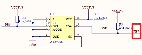
- F4_mini_PB7.jpg (21.22 KiB) Viewed 1448 times
I have reversed HREF polarity in OV7670 settings, so that HREF is logical “1” during V_SYNC (now both are “1”), and it started to run!
I think this is an undocumented “feature” of the DCMI interface.
The main issue was that the DCMI expects PCLK pulses during VSYNC, which was turned off by the live OV7670 project for F1.
A further problem is that high fps (>12) for ILI9341 can only be achieved by using 42MHz SPI clock. This however is supported only by SPI1, so I had to remap the SPI3 pins to use SPI1 because of some conflicting pins between normal SPI1 pins and DCMI.
The next issue is that the SPI with DMA does not work 100% together with DCMI, the system comes to its limits when both DCMI and SPI are activated for DMA2. The SPI part influences sometimes the DCMI sampling so that sometimes some bytes are lost causing ugly artifacts on the screen.
The workaround is to use the “normal” SPI.write(buffer, size) function instead of SPI.dmaSend().
This way ~26fps is reached for 320×240 resolution, which looks really nice ![]()
Resources needed:
Sketch uses 29712 bytes (5%) of program storage space. Maximum is 514288 bytes.

Global variables use 20496 bytes (15%) of dynamic memory, leaving 110576 bytes for local variables. Maximum is 131072 bytes.
Could you tell what is the “megapixel/second” limit of the STM32F4 alone (not including the SPI output to other device like display etc.)? The 320×240@26fps are almost exactly 2 megapixels (1.996) per second of data stream. I guess 640×480 may be possible with your setup at 26/4=6,5fps – is that a correct assumption?
The next issue is that the SPI with DMA does not work 100% together with DCMI, the system comes to its limits when both DCMI and SPI are activated for DMA2. The SPI part influences sometimes the DCMI sampling so that sometimes some bytes are lost causing ugly artifacts on the screen.
By the looks of it your using DMA twice by transfer from DCMI_DR to heap then from heap to SPI_DR. You can simply use DMA to transfer from DCMI_DR to SPI_DR.
Again I am a noob but this what I have found. DMA only does memory to memory transmissions. The docs are a little ambiguous about they way they describe DMA. The docs refer to memory to memory, peripheral to memory and memory to peripheral transfers, all 3 transfer types in fact are memory to memory transfers it is just what the timing of the transfers is triggered by. Memory to memory transfers will move the data from address in DMA_SxPAR to address stored in DMA_SxM0AR as fast as possible. Peripheral to memory transfers will move the data from address in DMA_SxPAR to address stored in DMA_SxM0AR at a speed triggered by the channel set in DMA_SxCR.
You should be able to place the address of DCMI_DR into DMA_SxPAR and the address of SPI_DR into DMA_SxM0AR then set the channel as DCMI then DMA will transfer from DCMI_DR to SPI_DR at a speed triggered by DCMI. You will have to make sure that the camera is set to a speed slow enough that it doesn’t out run the SPI other wise DMA will be transferring the data faster than the SPI can write it and some data will be lost.
With the 4 step process : 1. import from camera to memory, 2. export to SPI, 3. process to JPG, 4. send via USB on a 160×128 x 16bit colour I could still get 30 FPS running in a high level language like MicroPython. Using a low level language like C and just doing a 1 step process of using DMA to move from camera to SPI in monochrome you should be able to get decent frame rates.
see my video https://www.youtube.com/watch?v=onzi71RsGXw
The F4 should be also capable to process that low resolution with similar fps.
One could theoretically send the DCMI data directly to SPI, but i did not try it yet.
The F4 should be also capable to process that low resolution with similar fps.
One could theoretically send the DCMI data directly to SPI, but i did not try it yet.
Yes I was using the M7 with a STM32F7 chip but for DMA transfers what CPU it has doesn’t matter because DMA operates on separate circuits outside CPU. The STM32F7 will make the processing of the image into a JPG format faster as that is processing.
Always your only as fast as your slowest bottle neck and this will be the SPI. I am new to STM32 but if I am reading the docs correctly the STM32F4 has SPI1 max speed of 42MHz. If using 8bit grey scale with res as high as 480 x 320 then doing the math you still should be able to get 30FPS with DMA transfer from DCMI to SPI, would be interesting to see if someone can do this.
If they really wanted a higher frame rate then to look at using 1 of the STM32 chips that support QSPI.
Could you tell what is the “megapixel/second” limit of the STM32F4 alone (not including the SPI output to other device like display etc.)? The 320×240@26fps are almost exactly 2 megapixels (1.996) per second of data stream. I guess 640×480 may be possible with your setup at 26/4=6,5fps – is that a correct assumption?
The question was asked about streaming 320×240 monochromatic image to an Allwinner H2/H3 board over SPI.
It could be possible at this 320×240 res in 8 bit greyscale to get as high as 60FPS
[flyboy74 – Fri Aug 10, 2018 11:05 am] –
The question was asked about streaming 320×240 monochromatic image to an Allwinner H2/H3 board over SPI.It could be possible at this 320×240 res in 8 bit greyscale to get as high as 60FPS
Nice. This gives theoretical SPI clock around 36 MHz which is under the 42 MHz limit. I would like to use OV7670 because it is cheap but the problem is it does not support plain 8 bit greyscale. There would either have to be a conversion from RGB565/555 on STM32 or I would have to use either YUV422 or GRB422 directly to SPI. I am afraid the latter two carry worse monochromatic information than plain 8 bit mono after conversion to greyscale though.
Actually I would be happy with any monochromatic data over the 4 bits of luma in YUV. Currently researching on the various color formats and their conversions to greyscale. I am not sure whether using 8 bit over 16 bits of data from camera to STM would bring more FPS from camera – could you tell?
As flyboy74 said, the bottleneck is the getting the data out from the cam chip.
If you make onboard processing then keep in mind that no other DMA2 process may run in parallel with DCMI.
I do also need to frame synchronize two units (unit=OV7670+STM32F4) to create a stereo camera system. I got a hint from indrekluuk that I could probably simply start first camera and wait to its VSYNC, then stop the XCLK to this camera (=pause it?), then wait for VSYNC on the second camera and then release the first camera again (=start its XCLK again). Do you think this will work?
I see the camera.waitForVsync and camera.waitForVsyncEnd functions in the code an this would be the place in code to implement my code for synchronization I guess. If the camera can not run at fixed FPS (I guess it lowers FPS in low light by default?) then the synchronization will need to proceed every frame (because of AEC) or I would also have to force both units to use the same exposure time (run one master with AEC and copy its value to slave camera continuously).
OK I think there is a number of options you can explore.
1.
Using a camera that has a 8 bit grey scale will make things easy as you can then just use DMA to move it from DCMI output register to the SPI input register which is a simple process and will give you the speed and data width that you want. The OV7725 that OpenMV use does do grey scale and I didn’t release that the OV7670 didn’t.
search for OV7725 finds lots of options with price close to OV7670 https://www.aliexpress.com/wholesale?ca … ule+OV7725
edit : I am just having a quick look at the datasheet for the OV7725 and can’t see how to set it up as 8bit grey scale.
2.
I did glaze over without reading the DCMI data formats. I sort of though that maybe the DCMI can convert data formats on the fly i.e 565RGB to 8bit monochrome but not sure as didn’t read it close to understand what it does.
3.
Use DMA to move the data from the camera to the heap then process it to get what you want then move it a second time to the SPI. This will take the most amount of programming and probably the slowest.
So this means that you can use the the cheap OV7670 camera but you will need move the data from from DCMI to the heap then process it to extract the Y then send it to SPI. To be able to time all this to be able to get SPI running at max speed is likely to be a bit more difficult.
My mind boggles about thinking about this could be done.
At low res like 320×240 the OV7670 can do very high frame rates (i think 120FPS but not sure) so it will be easy enough to make the camera run at what ever Pixel clock output is needed and the DCMI and DMA will easily be able to cope with what ever speed is needed to get the data to the heap.
Timing the processing of each pixel to output the Y to the SPI at a speed in the MHz might be a little trickier.
Read the manual on Chrom-Art Accelerator™ controller (DMA2D) especially the pixel format converter (PFC)
If I am reading it correctly it allows you to convert from RGB565 to L8 or even L4 on the fly during the DMA transfer. This would allow for very high frame rate from camera DCMI to allwinner via SPI and once you understand just how the PFC works it shouldn’t take very many lines of code at all.
On F407 only the DMA driven solution is supposed to work, and only with restriction, because the 2 or more parallel DMA2 accesses influences each other while DCMI is active, in the meaning that DCMI is disturbed by any other parallel DMA process causing artifacts on a TFT.
June 2018 RM0090 Rev 17 1/1747
1
RM0090
Reference manual
STM32F405/415, STM32F407/417, STM32F427/437 and
STM32F429/439 advanced Arm®-based 32-bit MCUs
How does 1 tell what is available on which chip as this reference manual groups all these chips docs together?
edit: I found a place that shows the difference https://www.st.com/content/st_com/en/pr … tId=SS1577
![[SOLVED] Discovery STM32F100RB — Trouble with timers and library structure](https://sparklogic.ru/wp-content/uploads/2019/11/st-stm32vl-discovery-90x90.jpg)


