http://wiki.stm32duino.com/index.php?ti … 7VET6_Mini
The main difference compared to the generic black F4 board is that the mini board has a 25MHz crystal.
And the LED is on PB9 instead of PA6/7.
Important:
In order to get the board run, value 25 (instead of 8) must be entered here: https://github.com/stevstrong/Arduino_S … cF4.c#L370
In Arduino IDE the Generic F407 series menu has to be selected.
Maybe we should add an additional selection item in Arduino menu the crystal frequency?
I just quickly tested LED blink (PB9), SPI 1 and 3 and all work.
UPDATE 20.11.3017
– added Wire lib to communicate with the on-board 24c08 Eeprom. (see: viewtopic.php?f=39&t=2804&p=37376#p37376)
I think we’d be better off with a new variant for this, or perhaps setup the build to allow this to be switched by a define from boards.txt
I think having to select the crystal freq each time, would be a pain. (though the IDE does remember the last setting)
With the same occasion I have reworked both txt files, moved the common parts from boards to platform.
This changes requested to change some of the F4 files, so I did that and some cleanup, too.
https://github.com/stevstrong/Arduino_S … db35b57fd2
https://github.com/stevstrong/Arduino_S … 888095d986
https://github.com/stevstrong/Arduino_S … 5a94811edf
https://github.com/stevstrong/Arduino_S … f84c4bb5cc
I have built all F4 targets, error-free.
Only the generic F4 series (black and mini) boards were tested, both work as expected.
I tried the software reset (SWRST), it clear the BUSY bit for the moment, but it gets set again after I release the SWRST bit.
I also tried the bus reset, no effect either, BUSY is set no matter what I try.
OTOH, software Wire implementation works, so the slave is definitively not blocking the bus.
Does anyone have a binary for this board with working I2C1 interface build with GENERIC or STM32duino core? i would like to investigate the signals at enable phase after reset.
I read several posts on internet and tried to implement every hint, but none of them helped.
I am trying to get desperate, it may be the interface faulty?
Can you try STM’s official core ? That would rule out a hardware fault in the silicon
I only found the Disco 407G the closest target supported.
EDIT
I checked the I2C part of ST official core , it does exactly the same as I do in the init phase.
Hmm.
It is really strange that the pins go low at once when I set the mode to GPIO_AF_OUTPUT_OD, and BUSY gets set.
Although I enable the I2C clock after the GPIOs are initialized, as recommended here: https://community.st.com/thread/43558-i … ent-168570
Sounds like a question for one of STMs own forums ![]()
I forgot to set the AF mode register correspondingly.
Funny, as soon as I set it right, it started to work…
Such is programming
(Roger, don’t ask me to prepare a PR, because I know now that I am not able to make a clean PR…
Hopefully you can merge the files from the patch.)
The i2c.cpp and header files had to be amended, too.
I introduced a new parameter for Softwire: SOFT_HSPEED, which generates ~1MHz clock.
Additionally, I moved the “digitalPinTo..(pin)” defines from variant header files to gpio.h, because they are common for all variants.
EDIT
All (scanning) examples were tested and they work.
I attach an example file to handle the on-board Eeprom.
[stevestrong – Mon Nov 20, 2017 10:08 pm] –
I finally managed to bring Wire lib on F4 to work, the new files are checked in with this commit: https://github.com/stevstrong/Arduino_S … 8d427d03f2
(Roger, don’t ask me to prepare a PR, because I know now that I am not able to make a clean PR….
Hopefully you can merge the files from the patch.)
The i2c.cpp and header files had to be amended, too.
I introduced a new parameter for Softwire: SOFT_HSPEED, which generates ~1MHz clock.Additionally, I moved the “digitalPinTo..(pin)” defines from variant header files to gpio.h, because they are common for all variants.
Thanks Steve
OK.
I’ll try to manually merge this when I get time.
Actually, if there is anything that needs to be manually merged, can you just raise and issue so I don’t forget
I just raised and issue for this change
I just downloaded Steve’s libmaple master branch and tried simple led blink sketch with F407VE mini board. Didn’t work so tried debugging with the new Atollic IDE and here’s the result:
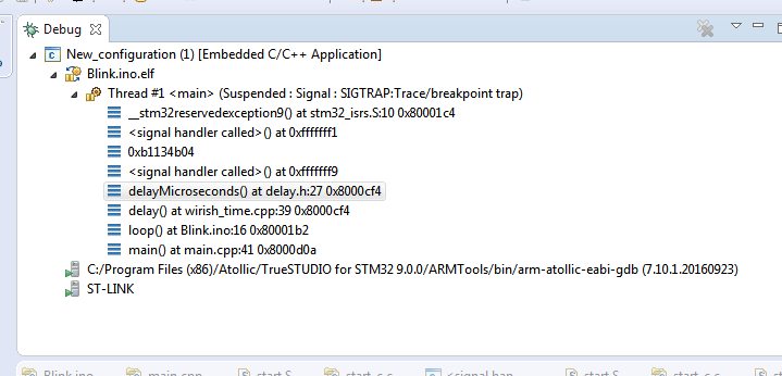
- bug.PNG (22.68 KiB) Viewed 437 times
[michael_l – Sun Jan 21, 2018 4:30 pm] –
Is this the correct place to report errors with Steve’s repo?I just downloaded Steve’s libmaple master branch and tried simple led blink sketch with F407VE mini board. Didn’t work so tried debugging with the new Atollic IDE and here’s the result:
Got blink to work but not serial USB…did you chose the the right board?
[Manny – Sun Jan 21, 2018 7:46 pm] –[michael_l – Sun Jan 21, 2018 4:30 pm] –
Is this the correct place to report errors with Steve’s repo?I just downloaded Steve’s libmaple master branch and tried simple led blink sketch with F407VE mini board. Didn’t work so tried debugging with the new Atollic IDE and here’s the result:
Got blink to work but not serial USB…did you chose the the right board?
Yes, I chose the right board (mini) and serial USB from the Arduino menu. The wiki suggests to check pull-up for the usb pin if it doesn’t enumerate. As we know It should be 1.5k. Have to check that next I guess.
[michael_l – Sun Jan 21, 2018 7:52 pm] –[Manny – Sun Jan 21, 2018 7:46 pm] –[michael_l – Sun Jan 21, 2018 4:30 pm] –
Is this the correct place to report errors with Steve’s repo?I just downloaded Steve’s libmaple master branch and tried simple led blink sketch with F407VE mini board. Didn’t work so tried debugging with the new Atollic IDE and here’s the result:
Got blink to work but not serial USB…did you chose the the right board?
Yes, I chose the right board (mini) and serial USB from the Arduino menu. The wiki suggests to check pull-up for the usb pin if it doesn’t enumerate. As we know It should be 1.5k. Have to check that next I guess.
I used st-link to upload the blink sketch using Steve core.
USB works fine with STM32Generic core, I just want to compare the Dhrystone benchmark between the both.
Could you try this version: https://github.com/stevstrong/Arduino_S … 8d427d03f2
Meanwhile I will check to see what is wrong there.
[stevestrong – Sun Jan 21, 2018 10:34 pm] –
Sorry, it seems that something went wrong by my previous commit, although I have tested it before.
Could you try this version: https://github.com/stevstrong/Arduino_S … 8d427d03f2
Meanwhile I will check to see what is wrong there.
Thanks, no problems. I’ll try that later in the evening.
I don’t know how you could compare the Dhrystone benchmark, because in the libmaple (Roger’s and my) version for F4 the FPU is not yet implemented. I have it on the “todo” list, but did not have yet the required time (also lacking motivation, I have no projects which involves FPU).
[michael_l – Mon Jan 22, 2018 2:39 pm] –[stevestrong – Sun Jan 21, 2018 10:34 pm] –
Sorry, it seems that something went wrong by my previous commit, although I have tested it before.
Could you try this version: https://github.com/stevstrong/Arduino_S … 8d427d03f2
Meanwhile I will check to see what is wrong there.Thanks, no problems. I’ll try that later in the evening.
Thanks, that commit seems to work!
Could I just copy FreeRTOS from F1 folder and change the freertosconfig.h, would that work ?
Also can I get the on-board sd card working ?
Thanks!
[michael_l – Mon Jan 22, 2018 4:33 pm] –
Could I just copy FreeRTOS from F1 folder and change the freertosconfig.h, would that work ?
Honestly, I don’t know, I’ve never tested FreeRTOS, nor any other OS.
Would be a good exercise for someone willing to test. ![]()
[michael_l – Mon Jan 22, 2018 4:33 pm] –
Also can I get the on-board sd card working ?
SDIO should work as it is listed to be supported here: http://stm32duino.com/viewtopic.php?f=39&t=1976
[stevestrong – Mon Jan 22, 2018 3:20 pm] –
@Manny,
I don’t know how you could compare the Dhrystone benchmark, because in the libmaple (Roger’s and my) version for F4 the FPU is not yet implemented. I have it on the “todo” list, but did not have yet the required time (also lacking motivation, I have no projects which involves FPU).
True but this is what I’m getting with STM32Generic …something definitely wrong there, got better numbers with a STMF103. ![]()
Microseconds for one run through Dhrystone: 15.16

Dhrystones per Second: 65958.27

VAX MIPS rating = 37.54
[stevestrong – Sun Jan 21, 2018 10:34 pm] –
Sorry, it seems that something went wrong by my previous commit, although I have tested it before.
Could you try this version: https://github.com/stevstrong/Arduino_S … 8d427d03f2
Meanwhile I will check to see what is wrong there.
I have a com port with that commit but nothing gets printed?
Dhrystone Benchmark, Version 2.1 (Language: C)

Execution starts, 8000000 runs through Dhrystone
Execution ends
Microseconds for one run through Dhrystone: 1.78
Dhrystones per Second: 562824.91
VAX MIPS rating = 320.33
I recently bought this board too. Although I can program it using my ST-Link, I cant getthe USB to work. If I have BOOT0 off, I get unknown device warning. Setting BOOT0 to on and the board is recognised but I get STM Serial (COM17), This device cannot start (code 10)
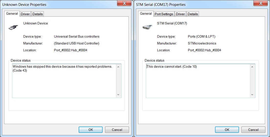
- usb.jpg (117.58 KiB) Viewed 343 times
Also the resistor dividers around boot switches have got values which are not the best choice.. I would replace the 10k pulldowns with something like 47k-100k..
..version for F4 the FPU is not yet implemented.
Quite a long reading on the FPU (407) viewtopic.php?f=39&t=2001&hilit=pito+fpu
######################################################

Demo sketch of STM32F4 SDIO (DMA) implementation.

######################################################

SdFatSdio begin() failed

Can't access SD card. Do not reformat.

No card, wrong chip select pin, or SPI problem?

SD errorCode: 0X20,0X0
[Pito – Mon Jan 22, 2018 8:35 pm] –
Does the SPI interface work with the sdcard?
I haven’t tried yet. But as said the card works okay. I should have one microsd module lying around somewhere… This board is new so I’ll have to check which pins are meant for SPI1
CS (or card select) is pin2 on the socket -> PC11.
[Pito – Mon Jan 22, 2018 9:01 pm] –
Insert your sdcard in the socket on your 407 mini board and try an SdFat SPI demo. Set the sdcard’s chipselect properly.
CS is pin2 on the socket -> PC11.
Thanks for the help! I loaded SdInfo.ino and set the chipselect to PC11 . But still same error:
SdFat version: 1.0.5
Assuming the SD is the only SPI device.
Edit DISABLE_CHIP_SELECT to disable another device.
Assuming the SD chip select pin is: 43
Edit SD_CHIP_SELECT to change the SD chip select pin.
type any character to start
error: cardBegin failed
SD errorCode: 0X20,0X0
Please check my posts regarding the SDIO development, and test that version with the timely corresponding repo version.
I do currently a global check on the F4 software, it it terrible…
It seems that even the NVIC structure is not corresponding to the Cortex-M4 spec.
Then RCC misses a couple of peripherals, ADC registers are not correct, BKP domain is different, and so on, so there is a lot of stuff to double-check again.
I am just wondering why it is working (at least was working before i tried to correct things and messed up) ![]()
Please give me a couple of days to finish my overview.
If someone has 100% working binary for this mini board I’d be happy to try it and verify my board is okay and reads sd cards correctly.
[michael_l – Mon Jan 22, 2018 9:24 pm] –
No problems, and thanks for your work. I can test when you are ready.If someone has 100% working binary for this mini board I’d be happy to try it and verify my board is okay and reads sd cards correctly.
SDIO benchmark using STM32Generic
File size 5 MB

Buffer size 32768 bytes

Starting write test, please wait.
write speed and latency
speed,max,min,avg
KB/Sec,usec,usec,usec
947.63,1367323,14610,34453
1224.07,1383979,14703,26644
Starting read test, please wait.
read speed and latency
speed,max,min,avg
KB/Sec,usec,usec,usec
2344.98,40740,11263,13972
2341.67,40895,13546,13995
Done
Type any character to start
I had no time yet to test SDIO, but the rest of peripherals should work ok.
[stevestrong – Tue Jan 23, 2018 9:59 am] –
My repo should be functional again.
I had no time yet to test SDIO, but the rest of peripherals should work ok.
Thanks for that . I’m still not getting any output using serial USB.
This is my blinky sketch:
#include <Arduino.h>
#define BOARD_LED2_PIN PA7 // on black F4
uint16_t counter;
// the setup function runs once when you press reset or power the board
void setup()
{
Serial.begin(115200);
while (!Serial);
delay(1000);
Serial.println("STM32F4 blinky...");
pinMode(LED_BUILTIN, OUTPUT);
pinMode(BOARD_LED2_PIN, OUTPUT);
counter = 0;
}
// the loop function runs over and over again forever
void loop() {
Serial.println(counter);
digitalWrite(LED_BUILTIN, LOW);
digitalWrite(BOARD_LED2_PIN, HIGH);
delay(250); // wait for a second
digitalWrite(LED_BUILTIN, HIGH);
digitalWrite(BOARD_LED2_PIN, LOW);
delay(250); // wait for a second
counter ++;
}
So it may happen that the hardware SDIO connection is different on this small board, I have to check that.
EDIT
I have checked the schematics, the only difference is that the mini F4 board has and additional line to pin 10 (!) marked as SW1 of the micro SD slot, connected to PA8.
Honestly, I don’t know what exactly this pins is good for. Maybe detect whether a card has been pushed in the slot?
[stevestrong – Wed Jan 24, 2018 2:24 pm] –
I admit, I tested the SDIO only with the black F4 board, but not with the (blue) F4 mini.
So it may happen that the hardware SDIO connection is different on this small board, I have to check that.EDIT
I have checked the schematics, the only difference is that the mini F4 board has and additional line to pin 10 (!) marked as SW1 of the micro SD slot, connected to PA8.
Honestly, I don’t know what exactly this pins is good for. Maybe detect whether a card has been pushed in the slot?
Bought a new card 4GB SDHC, inserted straight from the package with this message:
SdFatSdio begin() failed

Invalid format, reformat SD.
[stevestrong – Wed Jan 24, 2018 12:10 am] –
I just updated again my repo master branch, deleted all local files, cloned everything new from Github, compiled and I had working USB serial.I recommend you to first delete all local files before you download and extract files from the new ZIP of my repo.
Does you PC recognizes the USB as COM port? If not, you maybe need to install the official ST drivers.
Spot on …Installed STM’s virtual comport driver and now getting serial USB ![]() The few libraries with SPI like Adafruit_ILI9341_STM will not compile using the Blue mini board…I’ll leave that for another day.
The few libraries with SPI like Adafruit_ILI9341_STM will not compile using the Blue mini board…I’ll leave that for another day.
######################################################

Demo sketch of STM32F4 SDIO (DMA) implementation.

######################################################
init time: 8 ms
Card type: SD2
Manufacturer ID: 27

OEM ID: PH

Product: SD02G

Version: 3.0

Serial number: 97bdbf7c

Manufacturing date: 8/2011
cardSize: 1969.23 MB (MB = 1,000,000 bytes)

flashEraseSize: 128 blocks

eraseSingleBlock: true

OCR: 80ff8000
Volume is FAT16

blocksPerCluster: 64

clusterCount: 60086

freeClusters: 59559

freeSpace: 1951.63 MB (MB = 1,000,000 bytes)

fatStartBlock: 138

fatCount: 2

blocksPerFat: 235

rootDirStart: 608

dataStartBlock: 640
FreeStack: 61415

######################################################
Type any character to start

Test started - please wait, it may take up to 3 minutes
size, write, read

bytes, KB/sec, KB/sec

512, 190.70, 869.03

1024, 361.40, 1059.98

2048, 660.10, 2102.07

4096, 1133.33, 4088.29

8192, 1559.48, 5832.81

16384, 2007.64, 7714.63

32768, 2215.97, 8030.57
totalMicros  129325797

yieldMicros  96894938

yieldCalls   87623

yieldMaxUsec 152016

kHzSdClk     24000

Done
All the time I had used SdFat repo from greiman and added the correct define. So I suspect something may have gone wrong there. Now I checked out your SdFat repo with latest STM32 code and *boom* it works. I’m smiling ![]()
######################################################

Demo sketch of STM32F4 SDIO (DMA) implementation.

######################################################
init time: 8 ms
Card type: SDHC
Manufacturer ID: 74
OEM ID: J`
Product: USD
Version: 1.0
Serial number: ffed8041
Manufacturing date: 5/2010
cardSize: 4025.48 MB (MB = 1,000,000 bytes)
flashEraseSize: 128 blocks
eraseSingleBlock: true
OCR: c0ff8000
Volume is FAT32
blocksPerCluster: 64
clusterCount: 122592
freeClusters: 122591
freeSpace: 4017.06 MB (MB = 1,000,000 bytes)
fatStartBlock: 14468
fatCount: 2
blocksPerFat: 958
rootDirStart: 2
dataStartBlock: 16384
FreeStack: 61415
######################################################
Type any character to start
Test started - please wait, it may take up to 3 minutes
size, write, read
bytes, KB/sec, KB/sec
512, 186.33, 1288.61
1024, 366.88, 2439.33
2048, 753.58, 3998.89
4096, 1473.68, 6188.57
8192, 2750.75, 8051.64
16384, 4812.20, 9550.56
32768, 5132.90, 10442.53
totalMicros 107262334
yieldMicros 85513135
yieldCalls 114269
yieldMaxUsec 74701
kHzSdClk 24000
Done
Type any character to start
[Pito – Mon Jan 22, 2018 7:40 pm] –
@efftek: does the usb connector power the board actually? (sometimes the microsocket’s pins are not soldered properly).
Also the resistor dividers around boot switches have got values which are not the best choice.. I would replace the 10k pulldowns with something like 47k-100k
Hi Pito, sorry, been busy with builders and legal problems so haven’t done much for last few weeks. In reply, the usb turns on the power light, but the code loaded into the board – blink- doesn’t run. If I power the board from the st-link connections, it does.
Looking at the bottom of the board, not all the resistors etc are labelled. I did read about wrong value of usb pull-up resistor which the schematic lists as R8 and this is one of the unmarked ones. Also the 10k resistors you mention are also unmarked. Can anyone indicate which these are?
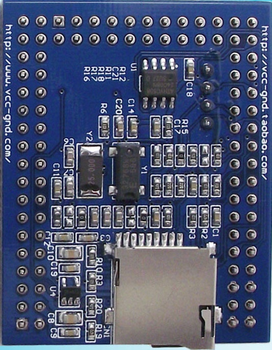
- EE7D118F-0095-477E-B83F-7D6A89B5FDBF.jpeg (185.13 KiB) Viewed 325 times
Once I replaced the hardware files with SteveStrongs github ones and reloaded the sketch via my st-link, everything is suddenly fine!
Yay….
[efftek – Tue Mar 06, 2018 1:43 pm] –
Update on above.Once I replaced the hardware files with SteveStrongs github ones and reloaded the sketch via my st-link, everything is suddenly fine!
Yay….
We are starting to have several “flavors” of cores in github branches. I see a dilemma coming with trying to support all this stuff… having to ask “which core” before answering and then trying to reconcile why one branch works and one branch does not work.
Ray


