Is anybody using this F4 board?
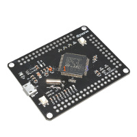
- 4048629366.jpg (27.28 KiB) Viewed 4375 times
Any documentation available?
I ma not sure, but it looks like a generic mini board: http://wiki.stm32duino.com/index.php?ti … 7VET6_Mini
Think this is the schematics i found on the net.
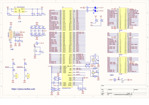
- DIY-More-STM32F407VGT6_smallest.png (137.59 KiB) Viewed 4355 times
Unfortunately the picture is very small size, hardly readable.
Can you post the ebay link?
[stevestrong – Sun Oct 08, 2017 9:02 am] –
It seems to be a very “basic” F4 version, without any additional chips on it.
Unfortunately the picture is very small size, hardly readable.
Can you post the ebay link?
This is the ebay link
http://www.ebay.com/itm/STM32F407VGT6-A … 1702413371
and link for the schematics.
http://dubstylee.net/v/wp-content/uploa … 07VGT6.png
[flodejr – Sat Oct 07, 2017 2:30 pm] –
I can get the usb to connect as DFU but it can’t work as USB device.
You mean is does not work as USB serial?
What/how did you try?
I don’t think the 1.5k is necessary on the F4. Its supposed to be inside the MCU
[stevestrong – Mon Oct 09, 2017 8:26 am] –
I don’t see any resistor on the USB_DP pin to be connected to Vcc. It should be one there with 1.5kOhm.[flodejr – Sat Oct 07, 2017 2:30 pm] –
I can get the usb to connect as DFU but it can’t work as USB device.You mean is does not work as USB serial?
What/how did you try?
I tried by using the cubemx and then specifying CDC Comms for USB_FS but no comm port appear both in linux and windows. I also tried the internal pull up on the DP like, but the comm port doesn’t appear. When I put boot1 to 0 and boot0 to X, the DFU appears on both linux and windows.
[RogerClark – Mon Oct 09, 2017 9:07 am] –
Steve,I don’t think the 1.5k is necessary on the F4. Its supposed to be inside the MCU
I tried the internal pull up on the MCU, but it doesn’t bring up the USB port, I think maybe I need to wire a 1.5K resistor externally. WIll there be a problem since there are no 22ohm terminating resisotrs on the DP and DM lines?
[RogerClark – Mon Oct 09, 2017 9:07 am] –
I don’t think the 1.5k is necessary on the F4. Its supposed to be inside the MCU
Makes sense, otherwise it would not work as DFU either.
I cannot help with Cubemx.
But I think it should work out of the box using the generic F4 board variant of the libmaple core.
Thanks! I got it working now. My error was that I only defined the USB OTG FS CDC device and the internal pull ups previously
To make it work, I will need to define a UART device + CDC Comm port and pull up on the D+ line in CubeMX. Although I don’t have to do anything on the UART side, it kind of automatically links the UART to the CDC device. Now I can see the /dev/ttyACM0 serial device on my linux box.
Also no terminating resistors required based on the specs.
2.2.30 Universal serial bus on-the-go full-speed (OTG_FS)
The STM32F405xx and STM32F407xx embed an USB OTG full-speed device/host/OTG
peripheral with integrated transceivers. The USB OTG FS peripheral is compliant with the
The USB 2.0 specification and with the OTG 1.0 specification. It has software-configurable
endpoint setting and supports suspend/resume. The USB OTG full-speed controller
requires a dedicated 48 MHz clock that is generated by a PLL connected to the HSE
oscillator. The major features are:
• Combined Rx and Tx FIFO size of 320 × 35 bits with dynamic FIFO sizing
• Supports the session request protocol (SRP) and host negotiation protocol (HNP)
• 4 bidirectional endpoints
• 8 host channels with periodic OUT support
• HNP/SNP/IP inside (no need for any external resistor)
• For OTG/Host modes, a power switch is needed in case bus-powered devices are
connected


