The STM32F4 version is taken from an old port of the original LeafLabs libmaple core, to F4 by the Aeroquad team.
Unlike the STM32F1 section, the F4 code has not been reworked to bring it up to the level of the Arduino 1.0 API, which means that a lot of the API calls you take for granted in the API are not present, also complete classes (Stream) are not implemented in the F4 version yet.
What needs to happen, is for the major restructuring that I did to the STM32F1 code to be applied to the F4 code, however I think an easier method to do the update, would probably be to make a copy of the F1 code, and then replace the files that were F1 hardware specific, with the files from the F4 folder.
However, its probably at least a whole day’s work, possibly more. I currently don’t personally have time to update the F4 code, but I’d be happy to answer questions from anyone who wanted to take the task on !
I did some basic tests, on a STM32F407 Discovery board, and GPIO works, however I was not able to get Serial to work (but this doesn’t necessarily mean its not working)
PS.
In the longer term, the goal should be to merge the F1 and F4 folders, but thats a long way off at the moment, and would require even more restructuring and code changes in both the STM32F1 and STM32F4 folders for this to be possible.
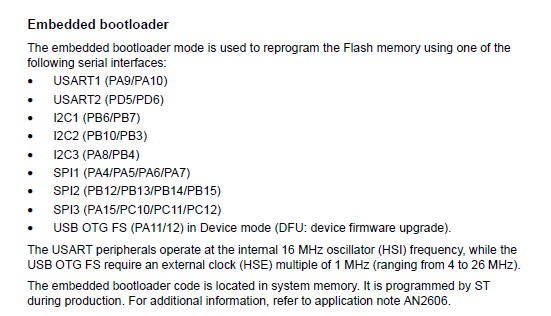
An extract from the reference manual is below.
Many of the STM32F’s have a bootloader in ROM, and the available serial interfaces it uses vary by chip type. Below are for the ‘411 chip.
ST has a free host-side loader, and the protocol is open source if you must DIY. For development, I use ST-Link which is internal to the IDE I use. But some users will prefer using a bootloader.
- 2016-04-02_130546.jpg (172.39 KiB) Viewed 14465 times
The STM32F4 version is taken from an old port of the original LeafLabs libmaple core, to F4 by the Aeroquad team.
Unlike the STM32F1 section, the F4 code has not been reworked to bring it up to the level of the Arduino 1.0 API, which means that a lot of the API calls you take for granted in the API are not present, also complete classes (Stream) are not implemented in the F4 version yet.
What needs to happen, is for the major restructuring that I did to the STM32F1 code to be applied to the F4 code, however I think an easier method to do the update, would probably be to make a copy of the F1 code, and then replace the files that were F1 hardware specific, with the files from the F4 folder.
However, its probably at least a whole day’s work, possibly more. I currently don’t personally have time to update the F4 code, but I’d be happy to answer questions from anyone who wanted to take the task on !
I did some basic tests, on a STM32F407 Discovery board, and GPIO works, however I was not able to get Serial to work (but this doesn’t necessarily mean its not working)
PS.
In the longer term, the goal should be to merge the F1 and F4 folders, but thats a long way off at the moment, and would require even more restructuring and code changes in both the STM32F1 and STM32F4 folders for this to be possible.
Simply start doing some code inspiring yourself with all the Arduino libs available on the Internet.
What kind of libraries are you planning to develop ?
Simply start doing some code inspiring yourself with all the Arduino libs available on the Internet.
What kind of libraries are you planning to develop ?
I have contacted Avik De who runs Koduino and he is very interested in the new STM core, so I would wait and see what STM release, later this week.
I have contacted Avik De who runs Koduino and he is very interested in the new STM core, so I would wait and see what STM release, later this week.
I do not know if this is the right place to post my question. I am new to STM32F407.
I bought several different STM32F407VET6 boards (I already use several different STM32F103 boards).
The one I try to start with using with Arduino IDE is:
https://www.aliexpress.com/item/Core407 … 45575.html
My questions are:
which board should I select to build for ? STM32 Discovery F407, or STM32F4Stamp F405, other ?
which download method should I select ?
There is a STM32 BOOTLOADER available on the USB connection, if started with BT0 high, but I don’t see it as a port.
I also have a SEGGER J-Link, that can be connected to the board, and a ST-Link V2, that I use with STM32F103C8T6 mini boards.
But for both cases I do not know what Programmer to select.
I hope someone can help me get started with the new boards. Thank you very much.
STM32 Discovery F407 supports upload only through ST-Link (boards.txt),
but my ST-Link V2 does not talk to the board when connected to the corresponding pins of the JTAG connector, like I do on some F103C8T6 board.
ST-Link Utility fails to connect.
STM32F4Stamp F405 supports upload only through maple_dfu,
but the dfu-util does not find the device 0483:df11 of the boards USB connection (id verified with Device Manager).
And connecting through a CT2104 USB device to the 4 pin header (tx, rx, GND, 5V) that connects to PA9, PA10 also doesn’t work:
Searching for DFU device [10C4:EA60]…
dfu-util – (C) 2007-2008 by OpenMoko Inc.
Couldn’t find the DFU device: [10C4:EA60]
Maybe I need to learn how to manually upload the code through SEGGER J-Link to the board.
Is this already described somewhere? link?
And then I need to add a Generic STM32F407 to my boards.txt
In the meantime I leave this frustration behind and turn to my Arduino Due to try to connect my 5″ 16bit TFT.
Jean-Marc Zingg
I have Windows and can’t upload via DFU to the built in bootloader in the F4 series. I think this is because the DFU protocol that STM use is non standard, and you can’t use dfu-util, you have to use STM’s own DFU program, and it only accepts a special format of file
So on Windows, the only way to upload to F4xx boards is via STLink or via serial (or Blackmagic probe)
It would be good if the maple / stm32duino bootloader was ported from the F103 to the F4 but I don’t have time to do that at the moment, as I’ve got too many other things I need to do, e.g. update the site to PHPBB 3.2 as well as a whole heap of PR’s on Github which need to be tested and them approved or rejected
std q what platform, os, version, arduino core(s) version/date please, what target board, picture maybe?
can you confirm the segger works with another board i.e. ribbon cable connection ?
i’m debian jessie on i7, one of my seggers works with segger linux software, the other isn’t even seen on the usb
i also have a real st-link egg that doesn’t work either, the others do though, i think i got invisible blue smoke somehow ![]()
you might consider using a ‘generic’ cpu, that should give st-link as an option.
st-link same question
usb stick or a an egg type? the egg uses a 20w idc ribbon
please try swapping the swclk/swdio leads as well
the upload methods are ‘defined’ in the boards.txt config file??
i’d search the forum for adding a new board, istr something on the wiki as well.
with my usb serial boards, i use grey to PA10, RX with white to A9, blk to gnd
with i2c with nano/uno A4 with yellow & A5 green, STM b6 blue & b7 purp
with spi1 y, grn,blue, purp
stephen
Sorry for the misinformation.
I will re-test USB to serial later, most likely I need to switch rx, tx; it is often unclear if the inking is for target or converter view.
So at least I have a working solution.
I work with Arduino 1.8 on Windows 10, the target system in question is the one the link is for.
Thank you for the support!
Jean-Marc
istr putting up links to a ‘manual’ of sorts, schematic and some sample software, although they’re for zet6 they should still be of some help.
i used chrome mainly for its translation, all i did was to browse the site.
also istr their search engine is a bit pedantic in the search string, case, type both upper/lower and stm32f407vet6/stm32f407zet6. ![]()
i’ve got a couple of both, still working on/with them. i’ve had both doing a blinky, but using libopencm3 and unicore-mx examples.
the directory structure for those is painful, but github does have repositories that ‘flatten’ it somewhat.
the peripherals still mapped the same e.g. i2c1 is still pb6 & pb7, spi1, spi2 etc, but hey that’s what symbols are for ![]()
stephen
I’m adding information as I go to the “older” wiki http://wiki.stm32duino.com/index.php?title=STM32F407. If others also working on these boards would like to add to the information, it would save some duplicated work.
I have also edited the F407 platform.txt file as it was missing some quote marks in the USB part of the build section. They don’t cause an issue unless there are spaces in your build path. Since most Windows folks have “/Program Files (x86)/Arduino/” in their path…
I’ll generate a pull request shortly.
RIchard
I’ll generate a pull request shortly.
RIchard
I have Windows and can’t upload via DFU to the built in bootloader in the F4 series. I think this is because the DFU protocol that STM use is non standard, and you can’t use dfu-util, you have to use STM’s own DFU program, and it only accepts a special format of file
So on Windows, the only way to upload to F4xx boards is via STLink or via serial (or Blackmagic probe)
It would be good if the maple / stm32duino bootloader was ported from the F103 to the F4 but I don’t have time to do that at the moment, as I’ve got too many other things I need to do, e.g. update the site to PHPBB 3.2 as well as a whole heap of PR’s on Github which need to be tested and them approved or rejected
I need to remap some timers out of the way to accommodate the hardwired SDIO socket and Winbond SPI flash. Are any (other than systick) needed for core operation? I particularly need to move TIM8, which was remapped in the F405 Disco board that I’ve used as a template.
same shop has this as the corresponding LCD product id on aliexpress 32746532235
this is first time i’ve seen a ‘corresponding display for a board’ in the blurb actually, so the more of us the merrier
to me that ‘corresponding display’ is worth paying the extra, now to get it displaying … …
stephen
I have put working copies of the core doco and the board files up on github. Definitely works in progress!
https://github.com/palmerr23/STM32F407
I’m currently working on the hardware I2C library, so will put WireBase… HWire… I2C…files up when I have them working. I’m stuck with there being no signals on the SDA/SCL pins at the moment in hardware mode, while software I2C works just fine on the same pins (different code, of course!).
As the hardware I2C library works fine on my maple mini, I’m rechecking F4 pins and AF assignments. I have already sorted out the GPIO register differences and they read just fine after HWire.begin().
*** See post below. It is compatible***
“Black” board TFT Port (ZET6 version – note PortF & PortG pins)
Port Function  Row   Function  Port

GND       1     LCD_RESET#

PD10 FSMC_D15  2     FSMC_D14  PD9

PD8  FSMC_D13  3     FSMC_D12  PE15

PE14 FSMC_D11  4     FSMC_D10  PE13

PE12 FSMC_D9   5     FSMC_D8   PE11

PE10 FSMC_D7   6     FSMC_D6   PE9

PE8  FSMC_D5   7     FSMC_D4   PE7

PD1  FSMC_D3   8     FSMC_D2   PD2

PD15 FSMC_D1   9     FSMC_D0   PD14

PD4  FSMC_NOE  10    FSMC_NWE  PD5

PF12 FSMC_A6   11    FSMC_NE4  PG12

PB0  T_SCK     12    T_CS      PC13

PF11 T_MOSI    13    T_MISO    PB2

PB1  T_PEN (irq) 14  LCD_BL    PB15

NC        15    GND

3V3       16    GND
re display pinouts, a) i’m just happy its got 34pins, not 32,36,40 etc, etc
i went through the f407zet ds and looked quite closely at the naming. might be i’ve got tired eyes, pretty sure the pinning was correctly named. it’s possibly not the best criteria, but the pcb is black ![]()
tomorrow, ok later on today after zzzz, i’ll check again … …
srp
visually ( & physically) map/match the SCK pin, the rest match
also the translation of the pin names to schematic to the FSMC maps as i expected.
yes, my first thought was have i made a ‘maybe oops’, then i applied the first line ![]()
stephen
As you say, It’s just a jump to the left. And then a step to the right…. and we all get to do the time warp again!
Your spatial sense is better than mine, I didn’t do the obvious first time round.
Have you seen the new F4 core release? I’ve just downloaded it and will give it a try later.
RIchard
Some new developments on the F4 front (thanks @ag123 for the topic references).
STM32GENERIC
@Danieleff has release a new “generic” STM32 core, which aims to minimise the effort to create variants for specific boards by making the core as flexible as possible (my paraphrase). First release 12 April 2017.
http://www.stm32duino.com/viewtopic.php?f=42&t=1966
ST’s core
Frederic Pillon (@fpiSTM) and several others have been working on delivering this core, and the F4 variant was first released on 1st April 2017.
http://www.stm32duino.com/viewtopic.php?f=48&t=1943
Arduino’s OTTO
The Arduino team have launched the OTTO – providing mainstream F4 support. (STM32F469, ESP8266 wifi, Additional SDRAM, SDIO, familiar MEGA footprint). http://www.arduino.org/products/boards/ … -star-otto
There are github repositories for all.
Several STM32duino contributors have been developing additional board variants for these cores. At least one STM F4 DISCO variant is available for both these cores.
My (in collaboration with @zmemw16) Black_STM407VET6 variant is available for the ST Core code https://github.com/stm32duino from https://github.com/palmerr23/Black-F407VET6-cube.
The board is inexpensive (~$15) and the full feature set is on the STM32duino Wiki http://wiki.stm32duino.com/index.php?title=STM32F407.
All of these excellent F4 cores are rapidly evolving, and adding features every week. They are already fit for purpose for a wide range of projects. Check the Issues pages on the githubs and the threads at the top of this post for which features are already enabled, and which are planned.
I hope this encourages more people to get on board the F4 train. The ride is pretty exciting at the moment for these powerful boards!
Excuse me for developed question of nucleo stm32f411 board. I use arduino IDE to develop firmware on nucleo stm32f411, but found problem.
Environment :
1. Ubuntu 14.04
2. Ardino IDE 1.8.3
3. Board NUCLEO F411RE
Question List:
1. Why does use “lsusb” command to detect NUCLEO F411RE boad to display information is “Bus 001 Device 000: ID 0483:374b STMicroelectronics ST-LINK/V2.1 (Nucleo-F103RB)”? Is it right to show Nucleo-F103R, not F411RE.
2. I had git clone Arduino_Core_STM32 to /arduino/hardware folder and intall STM32F4 Board info on arduino board manage, but I couldn’t select board item of “Arduino STM32F4 (32 bit ARM Cortex M4)” when upload code to Nucleo-F411RE. (Board option have to show “”Arduino STM32F4 (32 bit ARM Cortex M4)”, but can’t select it. ) What’s happen for the issue?
The below list is my operating step:
* Setup Nucleo-F411RE to download mode.
* Usb cable to connect PC and Nucleo-F411RE
* Open arduino and select board option to upload.
Terry
See the title of the thread…. “STM32F4 boards limited support” : My repo only has very limited support for F4 boards.
As you have a STM Nucleo board, you should use STM’s own official core, which supports that board.
2. off to check my setup, need to open the 411 plastic
Bus 003 Device 019: ID 0483:374b STMicroelectronics ST-LINK/V2.1 (Nucleo-F103RB)
mine selects ok, using nucleo-64 then it’s a sub-menu.
STM32GENERIC/STM32/boards.txt:NUCLEO_64.name=Nucleo-64 boards

vpv-STM32GENERIC/STM32/boards.txt:NUCLEO_64.name=Nucleo-64 boards

stephen@i71:~/sketchbook/hardware$ grep -R -i f411re */*/boards.*

STM32GENERIC/STM32/boards.txt:NUCLEO_64.menu.subboard.Nucleo_F411RE=Nucleo-F411RE

STM32GENERIC/STM32/boards.txt:NUCLEO_64.menu.subboard.Nucleo_F411RE.upload.maximum_size=524288

STM32GENERIC/STM32/boards.txt:NUCLEO_64.menu.subboard.Nucleo_F411RE.upload.maximum_data_size=131072

STM32GENERIC/STM32/boards.txt:NUCLEO_64.menu.subboard.Nucleo_F411RE.build.mcu=cortex-m4 -mfpu=fpv4-sp-d16 -mfloat-abi=hard

STM32GENERIC/STM32/boards.txt:NUCLEO_64.menu.subboard.Nucleo_F411RE.build.series=STM32F4

STM32GENERIC/STM32/boards.txt:NUCLEO_64.menu.subboard.Nucleo_F411RE.build.variant=NUCLEO_F411RE

STM32GENERIC/STM32/boards.txt:NUCLEO_64.menu.subboard.Nucleo_F411RE.build.board=NUCLEO_F411RE

STM32GENERIC/STM32/boards.txt:NUCLEO_64.menu.subboard.Nucleo_F411RE.build.extra_flags=-DSTM32F411RE

STM32GENERIC/STM32/boards.txt:NUCLEO_64.menu.subboard.Nucleo_F411RE.massstorage_drive=NODE_F411RE

STM32GENERIC/STM32/boards.txt:NUCLEO_64.menu.subboard.Nucleo_F411RE.build.f_cpu=100000000L

vpv-STM32GENERIC/STM32/boards.txt:NUCLEO_64.menu.subboard.Nucleo_F411RE=Nucleo-F411RE

vpv-STM32GENERIC/STM32/boards.txt:NUCLEO_64.menu.subboard.Nucleo_F411RE.upload.maximum_size=524288

vpv-STM32GENERIC/STM32/boards.txt:NUCLEO_64.menu.subboard.Nucleo_F411RE.upload.maximum_data_size=131072

vpv-STM32GENERIC/STM32/boards.txt:NUCLEO_64.menu.subboard.Nucleo_F411RE.build.mcu=cortex-m4 -mfpu=fpv4-sp-d16 -mfloat-abi=hard

vpv-STM32GENERIC/STM32/boards.txt:NUCLEO_64.menu.subboard.Nucleo_F411RE.build.series=STM32F4

vpv-STM32GENERIC/STM32/boards.txt:NUCLEO_64.menu.subboard.Nucleo_F411RE.build.variant=NUCLEO_F411RE

vpv-STM32GENERIC/STM32/boards.txt:NUCLEO_64.menu.subboard.Nucleo_F411RE.build.board=NUCLEO_F411RE

vpv-STM32GENERIC/STM32/boards.txt:NUCLEO_64.menu.subboard.Nucleo_F411RE.build.extra_flags=-DSTM32F411RE

vpv-STM32GENERIC/STM32/boards.txt:NUCLEO_64.menu.subboard.Nucleo_F411RE.massstorage_drive=NODE_F411RE

vpv-STM32GENERIC/STM32/boards.txt:NUCLEO_64.menu.subboard.Nucleo_F411RE.build.f_cpu=100000000L
It is now 2/25/2018 and STM32F407ZET6 boards are abundant and below $15 USD with standard connectors for LCD/Wireless/JTAG. A board with SRAM, LCD, 1100 meter 2.4Ghz wireless is under $30 and plug & play.
I downloaded the Arduino code but Blink failed, of course.
How about a new sticky thread for the black STM32F407ZET6 boards that everyone is selling?
Thanks
However, that is VE board, not ZE.
[stevestrong – Sun Feb 25, 2018 8:58 pm] –
You may find this useful: viewtopic.php?f=39&t=1976.
However, that is VE board, not ZE.
After spending some time looking for all the items needed to develop I found https://goo.gl/QFvRhd
STM32F407VET6
STM32F407ZET6
STM32F407ZGT6
From $10 ~ $16 from ACELEX
and
with a different layout
STM32F407ZGT6 https://goo.gl/xcPFMV at $14 + shipping
Combined with the 3.2″ LCD with Touch Screen and 2.4Ghz wireless 1000 meter device, these make a nice development platform.
makes me think of solving simultaneous equations ![]()
srp
I have been using F103 boards only until now, and upon reading all I could find about F4 support, I must admit I’m awfully confused, apologies for asking what’s probably a FAQ
Would https://github.com/stevstrong/Arduino_STM32/ be the best starting point, using a Generic board like this “Generic STM32F407V series”?
For discovery boards you may be eventually better served by the official or generic core.
[stevestrong – Sat Mar 03, 2018 7:56 pm] –
For generic boards, yes, depending on what your plans are.
For discovery boards you may be eventually better served by the official or generic core.
Fast answer from “the man” himself, what else can one ask for ![]() thanks!
thanks!
[KevinA – Sun Feb 25, 2018 8:41 pm] –
How about a new sticky thread for the black STM32F407ZET6 boards that everyone is selling?
You are free to do so.
But i will eventually not be able to contribute because i don’t own any zet6 board, i only have the generic and the mini vet6.
[KevinA – Thu Mar 01, 2018 7:25 pm] –
STM32F407ZGT6 https://goo.gl/xcPFMV at $14 + shipping
Combined with the 3.2″ LCD with Touch Screen and 2.4Ghz wireless 1000 meter device, these make a nice development platform.
I was searching for info about ZGT6, and found this thread…. To me the STM32F407ZGT6 board at https://bit.ly/2QeOEKy seems nice, as it would be easy to plug into another board… But the main question is whether the ZGT6 is supported yet.
Some pins have to be eventually re-mapped for LED and some peripherals.
But you are on your own with that, as I don’t have such a board.
However, creating a new variant is pretty straightforward, so it shouldn’t be very hard to do that.
// This must be a literal

#define NUM_DIGITAL_PINS        94

// This must be a literal with a value less than or equal to MAX_ANALOG_INPUTS

#define NUM_ANALOG_INPUTS       14
For the NUM_DIGITAL_PINS, this is because some pins have been duplicated for arduino compatibility.
For the ADC, this is due to the fact 2 pins are not proposed as ADC. That’s all.
And NUM_ANALOG_FIRST would be the num following the last definition in the array “extern const PinName digitalPin[];” ..
Also see: https://github.com/rogerclarkmelbourne/ … issues/335
Oh, btw, if you don’t need so many pins and so much flash, this is a cheaper alternative: https://www.aliexpress.com/item/STM32F4 … 85751.html
[palmerr – Thu Mar 30, 2017 6:57 am] –
https://github.com/palmerr23/STM32F407I’m currently working on the hardware I2C library, so will put WireBase… HWire… I2C…files up when I have them working. I’m stuck with there being no signals on the SDA/SCL pins at the moment in hardware mode, while software I2C works just fine on the same pins (different code, of course!).
As the hardware I2C library works fine on my maple mini, I’m rechecking F4 pins and AF assignments. I have already sorted out the GPIO register differences and they read just fine after HWire.begin().
Hello,
Does I2C work on the Black STM32F407VET6 generic board yet?
If your repo’s I2C indeed works, how does one install it in (or alongside) Arduino_STM32? Copy it to arduino/libraries, or arduino/hardware/?
Thanks in advance.
void loop() {
GPIOB->regs->BRR = 0x0008;

GPIOA->regs->ODR=(i);

GPIOB->regs->BSRR = 0x0008;

}
regs is defined in gpio.h. but there is no brr register, i think.
I’m using Roger Clark’s core Arduino_STM32
GPIOB ->regs – >BRR
GPIOA->regs->ODR
GPIOB->regs->BRR – working fine on F103R applies to
PIN_MAP[pin].gpio_device)->regs->BSRRL = BIT(pin&0x0F)?
But my F4 repo is a bit further developed, you could give it a try if you want to stick to Libmaple core.
See https://stm32duino.com/viewtopic.php?f=39&t=1976
The GPIO regs definitions in my repo are slightly different, see: https://github.com/stevstrong/Arduino_S … _def.h#L56
Also, the pin map as you know it from Roger’s repo doesn’t exist anymore.
https://github.com/stm32duino/Arduino_C … tm32f4xx.h
then you will most probably need at least one more header file, and you have to know the struct type definition.
Furthermore you have to know how the core types should be handled, meaning you actually have to use that core.
Same is valid for libample core.
void loop() {

// put your main code here, to run repeatedly:

//GPIOA->regs->ODR=(j);

GPIOC->regs->BSRRL = 0x2000;

delay(1000);

GPIOC->regs->BSRRH = 0x2000;

delay(1000);

}[stevestrong – Thu Jan 24, 2019 12:17 pm] –
If you mean, this header file
https://github.com/stm32duino/Arduino_C … tm32f4xx.h
then you will most probably need at least one more header file, and you have to know the struct type definition.
Furthermore you have to know how the core types should be handled, meaning you actually have to use that core.
Same is valid for libample core.
OK yes you will need another header file after taking a closer look it seems when I include “stm32f4xx.h” it in fact then just includes “stm32f407xx.h” so all the definitions are in the “stm32f407xx.h” file to write to all the registers on that MCU
Why will you need to know how core types should be handled?? As using the definitions in “stm32f407xx.h” will set a pointer directly to the register and write directly to it regardless what the higher level core is doing.
byte static flash[2]={156,156};

void setup() {

}
void loop() {

}
You posted sketch obviously does not entirely match the real code what you tested.
But you have to know what you are doing, and if you have later problems, a warning can be then relevant.
Please start a new thread about your project if you have more questions, because this here is not adequate to solve each of your small issues.
