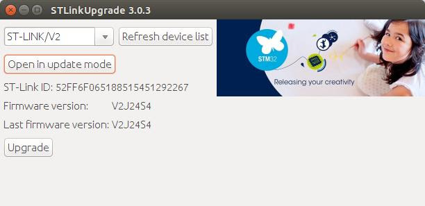
12/3/2016 – You can now contribute to developers of the Black Magic Probe project (which isn’t me) using paypal. Find and click the paypal contribute button here: https://github.com/blacksphere/blackmagic
12/8/2016 – Instead of using this port of Black Magic Probe, it is a lot easier to just compile the PROBE_HOST=stlink and load that onto your bluepill. The bluepill hardware is the same as the stlink v1/v2 hardware. Just follow the steps from the Black Magic Probe software for building and installing the BMP stlink platform. The advantage being, you will get the latest BMP version and you will be able to update future versions just using the USB cable on the bluepill with a program called usb-util. The posts in this thread can be thought of as an interesting read on my journey from bluepill newbie to a somewhat proficient users of it.
The Black Magic Probe is a modern, in-application programmer and debugging software for embedded microprocessors. It allows you to see what is going on ‘inside’ an application running on an embedded microprocessor while it executes. It is able to control and examine the state of the target microprocessor using a JTAG or SWD (Serial Wire debugging) port and on-chip debug logic provided by the microprocessor. The probe connects to a host computer using a standard USB interface. The user is able to control exactly what happens using the GNU source level debugging software, GDB. Read more about it here: https://github.com/blacksphere/blackmagic/wiki
However, the stm32duino crowd here will find the open source Black Magic firmware more appealing than the hardware. The Black Magic Probe firmware can be loaded onto the low cost stm32c8t6 boards you find on eBay. You can then use that clone board with BMP firmware to take the place of an ST-Link programmer. Once the BMP firmware is loaded on a clone board, it provides the ability to upload to the flash of another target board. It does this using a gdb server built into the BMP firmware. This allows for hardware debugging using just arm-none-eabi-gdb without any host server code.
I started with the latest github version of the Black Magic Probe software and added platform support for the stm32f103c8t6 boards you find on ebay. I call it the ‘jc66_coreboard’ platform, as that is the label printed on the silk screen. Any board with the same pin outs should work (See Red Pill Blue Pill post for more info about the hardware). The new platform is based mostly on the already existing stlink platform source with changes to support the different hardware pin outs and features.
The ebay “Red Pill” board loaded with the Black Magic Probe firmware acting like a programmer:

by Rick Kimball, on Flickr
Target board (another “Red Pill” board) connections from the “Red Pill” BMP programmer:

I’ve attached a zip file containing the blackmagic.bin file, the blackmagic elf file, and patch file for the source. ( NOTE: I will fork BMP github code and create a branch with the source changes). For now, just download and unpack the zip and then upload the bin or elf file to your jc66_coreboard.
If you want to build the source yourself, do something like the following:
$ git clone https://github.com/blacksphere/blackmagic

Cloning into 'blackmagic'...

remote: Counting objects: 3463, done.

remote: Compressing objects: 100% (2/2), done.

remote: Total 3463 (delta 0), reused 0 (delta 0), pack-reused 3461

Receiving objects: 100% (3463/3463), 1.70 MiB | 0 bytes/s, done.

Resolving deltas: 100% (2331/2331), done.

Checking connectivity... done.

$ cd blackmagic

$ unzip ../bmp_jc66_coreboard.zip

Archive:  ../bmp_jc66_coreboard.zip

inflating: blackmagic

inflating: blackmagic.bin

inflating: bmp_jc66_coreboard.patch

$ patch -p1 <bmp_jc66_coreboard.patch

patching file src/Makefile

patching file src/command.c

patching file src/platforms/common/cdcacm.c

patching file src/platforms/jc66_coreboard/Makefile.inc

patching file src/platforms/jc66_coreboard/Readme

patching file src/platforms/jc66_coreboard/jc66_coreboard.png

patching file src/platforms/jc66_coreboard/platform.c

patching file src/platforms/jc66_coreboard/platform.h

$ make

$ cd src

$ make install # assuming it go OK, you will have to change the path for the st-write utility to match your system
I’ve tried to install the BMP binary on 2 different C8 boards
This one didnt work, I just get unknown device on USB

However I have a feeling the board either has a defective USB connection or it doesn’t have a pull up resistor etc and will only work on USB with special firmware
The other C8 board, was fine (its the same board you have)
On Windows I had to download and install the drivers from here http://www.blacksphere.co.nz/downloads/ … 130819.zip
What does seem a bit odd, is that the drivers 2 years old http://www.blacksphere.co.nz/downloads/
I guess they have no need to update them, but I suspect that they may not work on Windows 10 without us re-packaging them (but its hard to know quite what Windows 10 will end up doing until its released)
I guess it doesnt really matter, but has BlackSphere given up selling the BMP ? There isnt a link to where you an buy it from, on their website. Well there is some text but no hyperlink
Is there any documentation about what GPIO pins on the flashed board need to be connected to the CLOCK and SDIO pins on the SWD connector ?
Do you know how the UART works, is this just a method to print debug messages
e.g. I found this code,
http://electronics.stackexchange.com/qu … d-using-gd
Is this the sort of UART functionality it provides ?
Thanks
Roger
Since I now have two of these ST-Link V2 clones it should be possible to use one to probe the other. They are also scarily cheap. If I get a chance I’ll try and reverse engineer the board and see if I can A) copy off the existing firmware, and B) figure out if we have enough pins etc to re-purpose it as a Black Magic Probe.
This one didnt work, I just get unknown device on USB
I included support for reading the target boards VCC voltage. I found a patch on blackmagic mailing list
http://sourceforge.net/p/blackmagicdebu … /33693983/. I slightly modified it to fit the hardware on this board. To use this feature you need to do some things:
o Add a voltage divider and diode on pin PA0.
Use 4k7 resistors and connect to your TARGET VCC (On the c8 board it is broken out with the SWD pins)
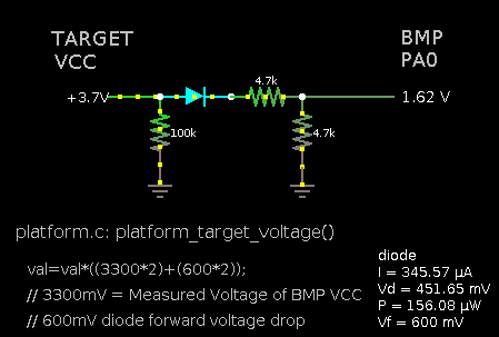
- pa0_diode_circuit.png (5.17 KiB) Viewed 28618 times
Since I now have two of these ST-Link V2 clones it should be possible to use one to probe the other. They are also scarily cheap. If I get a chance I’ll try and reverse engineer the board and see if I can A) copy off the existing firmware, and B) figure out if we have enough pins etc to re-purpose it as a Black Magic Probe.
If you could point me to some directions I can read and try to figure it out.
thanks.
victor_pv wrote:Rick, is there a way to use BMP and GDB on windows with the Arduino IDE? I have never used either, so I am getting a bit lost at what is needed. If you could point me to some directions I can read and try to figure it out. thanks.
Here is what it looks like when you have verbose upload turned on with the Arduino IDE on linux:
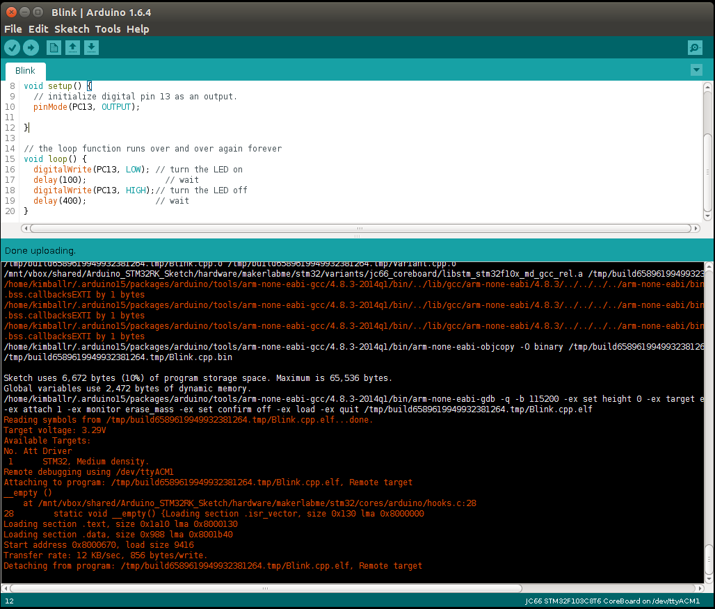
- makerlabme_gdb.png (82.85 KiB) Viewed 28603 times
I think that code should work on Windows, but for greater compatibility for anyone on IDE 1.6.1 or earlier I think the path to GDB needs to be changed to the same path that is defined at the top of platform.txt, and then allow the rewrite-keys to handle changing it if necessary
With my other C8 board.
It could just be the board is defective.
Re: connections
After I posted, I managed to find a schematic of a derivative of the BMP called the Cricket Probe, and I can see that the BMP uses serial port 1 to connect to the target, as well as the SWD connection.
I will have a go at using the same model of F103C8 board that you use, and connect to my ZET board.
@ahull
Re: flashing an STLink.
I noticed in the GitHub code that there is a target of STlink, rather than the target of STM32 which I think rick may be using.
I was debating whether to reflash my STLink as a BMP, as I read the article you linked to and then tracked down the Stlink binary it referenced, on a Russian website.
However my stlink board only has the SWD pins broken out to a connector, so connecting a USB to serial to it, and pulling boot 0 high, in order to flash it, would be difficult.
In the longer term I may however reflash by F4 Discover stlink as its a pain needing a separate USB to serial for comms, I.e the Discovery stlink firmware doesn’t come with the virtual serial like the Nucleo firmware does ![]()
After I posted, I managed to find a schematic of a derivative of the BMP called the Cricket Probe, and I can see that the BMP uses serial port 1 to connect to the target, as well as the SWD connection.
tools.sloadhost.upload.pattern="{path}{cmd}" -b 38400 -ex "set debug remote 0" -ex "set confirm off" -ex "set height 0" -ex "target extended-remote {serial.port}" -ex "mon swd" -ex "shell sleep 2" -ex "echo \nattach...\n" -ex "attach 1" -ex "shell sleep 2" -ex "x/wx 0x8000004" -ex "monitor erase_mass" -ex "x/wx 0x8000004" -ex "load" -ex "x/i *0x8000004" -ex "break main" -ex "run" -ex "echo \n\n\n{build.project_name}.elf uploaded!\n" -ex "quit" "{build.path}/{build.project_name}.elf"
tools.sloadhost.upload.pattern="{path}{cmd}" -b 38400 -ex "set debug remote 0" -ex "set remotetimeout 10" -ex "set confirm off" -ex "set target-async off" -ex "set height 0" -ex "target extended-remote {serial.port}" -ex "mon swd" -ex "attach 1" -ex "x/wx 0x8000004" -ex "monitor erase_mass" -ex "echo address value should be 0xffffffff after erase\n" -ex "x/wx 0x8000004" -ex "file {build.path}/{build.project_name}.elf" -ex "load" -ex "x/i *0x8000004" -ex "break main" -ex "run" -ex "echo \n\n\n{build.project_name}.elf uploaded!\n" -ex "quit"
Thanks.
Work is a bit busy for me at the moment, but I’ll give it a try this evening (my time)
Cheers
Roger
This patch will add a BMP uploader feature to the generic stm32f103c boards. Apply it to the latest stm32duino source code. Someone with windows and OS/X might want to try this and see if it works.
$ # kill any running arduino sessions
$ cd Arduino_STM32
$ unzip bmp_upload.patch.zip
$ patch -p1 <bmp_upload.patch
$ # restart arduino
-rick
Patch seems to be safe, and appears to do what you describe.
IDE still compiles code, but since I have no BMP to play with (yet…. give me time)… it fails with the following message..
COM1: No such file or directory.

"monitor" command not supported by this target.

Don't know how to attach.  Try "help target".

Cannot access memory at address 0x8000004

"monitor" command not supported by this target.

Cannot access memory at address 0x8000004

You can't do that when your target is `exec'

The program is not being run.

Don't know how to run.  Try "help target".

The program is not being run.
Do you have a spare F103C8 board, if so you just flash Ricks binary into it.
I flashed by spare board and it enumerates fine on windows, but I’ve been a bit preoccupied trying to unify the bootloader that victor made for generic boards with the existing bootloader, and I’ve also been trying to get DDD working on windows ( see my post in the general discussion thread)
I’m happy to add upload to BMP as an option on all generic boards, as I see this as a low risk change, as its just adding new features and should not disturb the old ones.
I must admit I’m surprised about how few people are interested in In Circuit debugging, but it could be just a catch 22 situation at the moment, with both the lack of easily available hardware and software, and no windows GUI.
FYI. Just as a matter of interest, I flashed Ricks previous bin to my F103ZET board, and it enumerates fine as a BMP !
I don’t intend to use it as a BMP, but I accidentally flashed a HTML page to it, (I must remember right clicking and saving links to files in github does not save the bin file !!!)
So rather than leaving complete junk code in the board, I immediately flashed what I had to hand which was BMP !
I’ve been flat out with work recently and have had very little free time, so have not had time to wire up my C8 as a BMP yet, but I will hopefully have some time at the weekend
I’m not sure why, but when I tried to apply your patch, I couldn’t get MinGW patch to patch the file
Basically it rejected the patch and didnt modify either file, it just spat our some .rej and also some orig files instead
But as it was a really small patch I’ve applied it my hand and I will push to the repo…
However I’m not sure it works on Windows.
I get these messages when I ran it
GNU gdb (GNU Tools for ARM Embedded Processors) 7.6.0.20140228-cvs
Copyright (C) 2013 Free Software Foundation, Inc.
License GPLv3+: GNU GPL version 3 or later <http://gnu.org/licenses/gpl.html>
This is free software: you are free to change and redistribute it.
There is NO WARRANTY, to the extent permitted by law. Type “show copying”
and “show warranty” for details.
This GDB was configured as “–host=i686-w64-mingw32 –target=arm-none-eabi”.
For bug reporting instructions, please see:
<http://www.gnu.org/software/gdb/bugs/>.
0x8000004: 0x8000004 expect 0xffffffff after erase
COM3: No such file or directory.
“monitor” command not supported by this target.
Don’t know how to attach. Try “help target”.
Cannot access memory at address 0x8000004
“monitor” command not supported by this target.
Cannot access memory at address 0x8000004
C:UsersrclarkAppDataLocalTempbuild7632203454613856955.tmp/usb_test.cpp.elf: No such file or directory.
No executable file specified.
Use the “file” or “exec-file” command.
Cannot access memory at address 0x8000004
The program is not being run.
No symbol table is loaded. Use the “file” command.
Don’t know how to run. Try “help target”.
The program is not being run.
0x8000004: Starting program:
usb_test.cpp.elf uploaded!
I’m going to write a window batch file to handle this on windows, I suspect it would be best to do the same on Linux, as its far easier to do stuff in a script than in one line in platform.txt
o modified command line args in platform.txt (boards.txt did not change)
o removed windows batch file usage
o tested successfully on both windows and linux, (nice if someone could try on OS/X
[/EDIT]
full boards.txt and platform.txt as a zip
- patched_stm32f1_txt_v1.zip
- (4.99 KiB) Downloaded 82 times
No worries
I’m just doing the ancilliary script for Windows, hopefully the Linux stuff will be left untouched.
I’m looking at the windows bat file now, but I don’t know if I will get it finished tonight, as its 9:45 already and I have to make an early start tomorrow ;-(
Edit.
Seems a bit better when I use an external script
This is the final command string that is being called
C:\Users\rclark\Documents\Arduino\hardware\arduino_stm32\tools\win>C:\Users\rclark\AppData\Roaming\Arduino15\packages\arduino\tools\arm-none-eabi-gcc\4.8.3-2014q1/bin/arm-none-eabi-gdb.exe -b 230400 -ex “set debug remote 0” -ex “set target-async off” -ex “set remotetimeout 60” -ex “set confirm off” -ex “set height 0” -ex “target extended-remote COM3” -ex “monitor swdp_scan” -ex “attach 1” -ex “x/wx 0x8000004” -ex “monitor erase_mass” -ex “echo 0x8000004 expect 0xffffffff after erase\n” -ex “x/wx 0x8000004” -ex “file C:\Users\rclark\AppData\Local\Temp\build8034241370519985939.tmp\sketch_may19a.cpp.elf” -ex “load” -ex “x/i *0x8000004” -ex “kill” -ex “tbreak main” -ex “run” -ex “detach” -ex “echo \n\n\n uploaded!\n” -ex “quit”
which strangely doesnt seem to give the same errors, even though the only fix up is the last slash in the elf file
I can’t fully test this, as I’ve not wired up my BMP to another board, I’m just running it on its own.
Anyway, I’ll commit the changes as they currently are, so you can check I’ve manually patched things correctly, and I’ll try to find time to wire up my BMP to another board tomorrow
I’ve pushed the changes
Rick, can you see if my manual patching is OK for you.
Cheers
Roger
Do you know much about the argument quoting in platform.txt?
Here is what it looks like on windows xp:
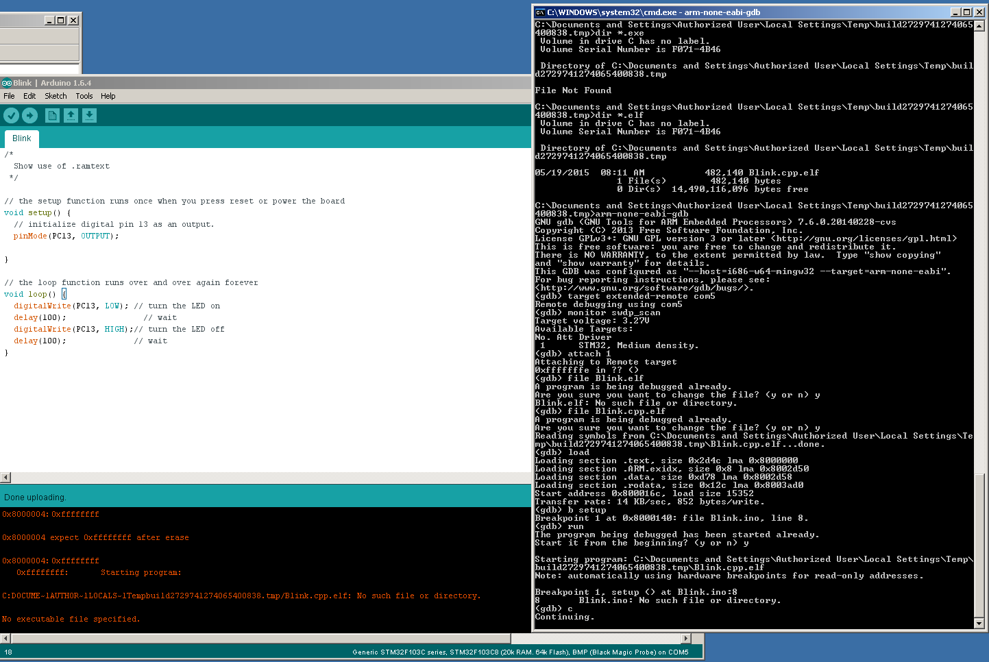
- win32xp.png (69.58 KiB) Viewed 949 times
-rick
Thanks
I will give that a try
Can you confirm the electrical connections.
In one of your previous postings, you said it needs between 10k and 100k pullup and 22 ohms inline. with TCK and TDIO
However I’ve looked at the BMP schematics https://raw.githubusercontent.com/wiki/ … c_mini.pdf and and https://raw.githubusercontent.com/wiki/ … ic-1.0.pdf
and I can’t see anywhere on either schematic that has those resistors
Is this a later addition than the pdf’s that are on GitHub.
Edit.
I tried your new upload pattern and it seems OK on Windows 7
However I have not connected my C8 BMP to another board as I’m not sure about the connections.
BTW. I had something strange go on with the USB Enumeration on Windows. I plugged in my F103ZET board that still has BMP flashed to it, but Windows initially reported unknown USB device (just on device), so I disconnected and connected my by F103C8 board with BMP on it, and I got the same result.
So I connected my STLink to reflash the C8 board and Windows then decided it could see the BMP USB devices
and now when I disconnect and reconnect either board all the BMP usb devices are enumerating OK
It looks like enumeration may be a bit flakey, but I guess thats a small price to pay for using an unmodified board as a BMP
BTW. Looking at the schematics it looks like BlackSphere are using PA8 for USB enumerayion, as its 1.5k to USB D+ so looks suspiciously as USB re-enumeration hardware
http://www.stm32duino.com/viewtopic.php … t=30#p1169
You do not need any resistors, inline or pull-down or pull-up. I’ve left this post here to
let you see how I had previously decided to suggest the use of them.
In one of your previous postings, you said it needs between 10k and 100k pullup and 22 ohms inline. with TCK and TDIO
So I connected my STLink to reflash the C8 board and Windows then decided it could see the BMP USB devices
and now when I disconnect and reconnect either board all the BMP usb devices are enumerating OK
It looks like enumeration may be a bit flakey, but I guess thats a small price to pay for using an unmodified board as a BMP
I had looked at the BMP Native schematic and compared it to the STLink one and wondered why the BMP didn’t have any resistors.
I have been testing with with my jc66_coreboard on a breadboard. I hadn’t removed it from the breadboard before I started testing all this stuff. After a conversation in ##stm32 about the proper resistors for the SWD lines. They suggested that no resistors are needed. I pulled my jc66_coreboard with the BMP firmware off the breadboad and just connected the wires directly to my target board and it worked just fine.
So you probably don’t want your BMP board on a breadboard when you are trying all this out. If you do the capacitance on the breadboard might be causing issues. By the same token, if your target board is on a breadboard it might also cause problems.
The bottom line don’t use any resistors between the BMP and the target.
Thanks go to the ##stm crew!
[Edit]
And here is why we don’t need pull downs and pull ups ( they are internal )
http://www.st.com/web/en/resource/techn … df#page=19
[/Edit]
-rick
-rick
With the pull up or pull down
As the value of the pull-up is between 10 and 100k, is there any reason that the BMP code doesn’t use the internal pull up or pull down as required.
According to the page you liked to, TCK is always pulled pow, and TDIO always is pulled up.
I’m not sure why TCK needs to be pulled down, I didn’t realise it was bidirectional pin.
But I can see why TDIO needs to be either open collector or input pull up etc.
But I can see why TDIO needs to be either open collector or input pull up etc.
No worries
When I get chance I’ll try hooking it all together, but I’ve had some other non-Arduino stuff I’ve needed to do over the last few days
Cheers
Roger
I’m not sure why TCK needs to be pulled down, I didn’t realise it was bidirectional pin.
But I can see why TDIO needs to be either open collector or input pull up etc.
Does anyone have a schematic for these boards I didn’t see a transistor that might be used to control it. Hmm .. bummer.
-rick
It’s probably got either no resistor or a high value.
Would it be possible to turn on the internal pull-up. I know its a high value ( I can’t recall what value), but the internal and external values in parallel may be enough to re enumerate.
Also how about putting the USB pin, (pa12) into push pull and driving it high
I cleaned the board to make sure flux wasn’t any issue and now it works. But it still measures 10k .. so I have no idea what is going on there. On the red board I can identify the 1.5k resistor. On this board there is no 1.5k resistor in sight.
BTW: I’m talking about this specific blue pill board http://www.ebay.com/itm/321569700934
-rick
OK.
Shame the Blue boards are different from the red ones. Well, it actually sounds like there are red boards that exhibit the same traits as the blue boards or a mix of traits.
I would suggest that we post a picture of the boards that work, but… I know a lot of eBay vendors just use stock images, so there is no way to know for sure you will get whats in the picture, unless you pre-confirm with the vendor first.
Dark here now. I’ll do it tomorrow.
-rick
Maybe it would help to post your “good board” sellers here?
We could try the list of good sellers, but its possible they change stock, and don’t get the boards they think they get.
I had an issue I posted about with a “CC Debugger” clone, and the seller had 100% rating and had sold 8 others and no complains, but mine didnt have any firmware ![]()
~Straw
~Straw
 bluepill_top by Rick Kimball, on Flickr
 bluepill_bottom by Rick Kimball, on Flickr
R10 .. is a 10k .. that is connected to VCC and PA12 (USBDP+)
the hole next to C6 is PA12.
Has anyone seen that voltage regulator before (U1) ? It seems puny.
-rick
Dont know who is making U1, but i think its a 150mah one, (also Seen on arduino pro mini?)
~
I also added a picture of the stm32c8t6 “Red Pill” board I’m using as the Black Magic Probe hardware and how you connect it to a target device. Re-reading what I originally wrote, it wasn’t obvious in the first few paragraphs which hardware I was using. Hopefully, you can see that now with pictures.
-rick
I am waiting on one to arrive. Would be great if I can swap the fw to a Black Magic, but I still don’t have it so I don’t even know what pins it uses.
EDIT: I see you are including the source, so hopefully the pins can be changed. I’ll check that pins are connected in the st-link clone once I get it.
I think the main issue with flashing BMP onto an STLink is access to the pins in order to program it.
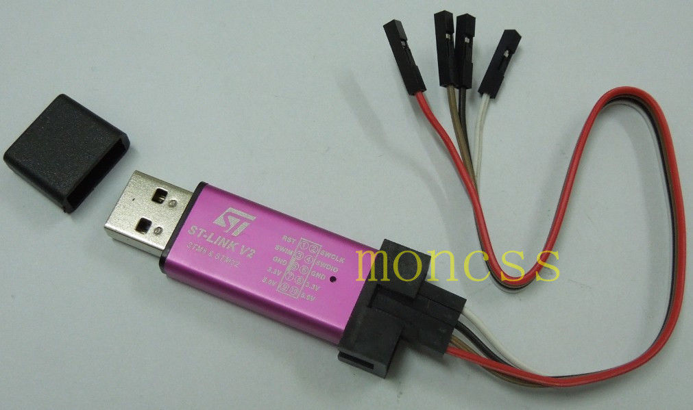
My STLink looks like this
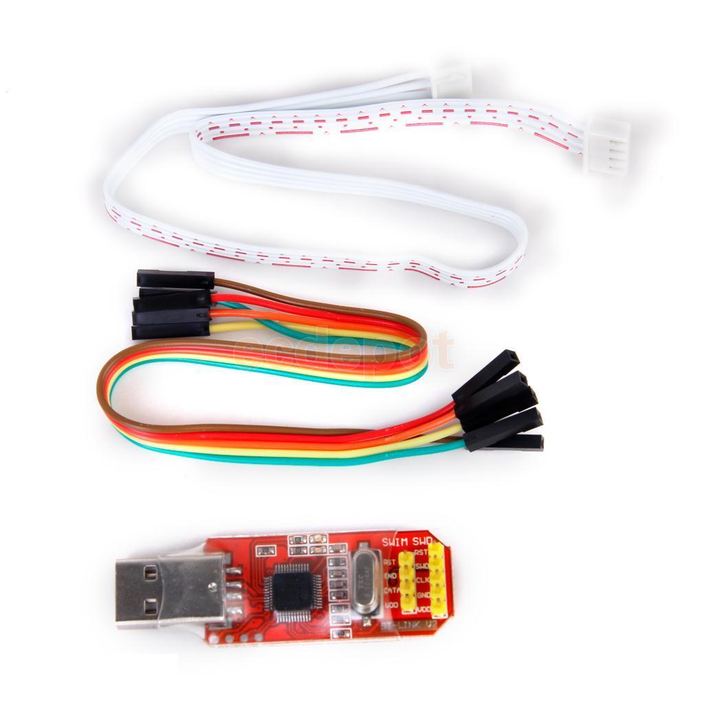
I can see 4 through holes, which may be for reflashing, as one of the wholes seems to have a track to PA14 which is SWD Clock.
As they are more expensive than the BluePill / red pill board and also don’t have access to PA9 and PA10 for USB Serial via the BMP’s own usb to serial driver, I’m not sure its worth buying one.
I know that Andy has a different STLink (in a box), so I wonder if that one is any better.
I think he has this one
Personally I’m going to flash BMP onto the Red Pill and use that.
I am waiting on one to arrive. Would be great if I can swap the fw to a Black Magic, but I still don’t have it so I don’t even know what pins it uses.
EDIT: I see you are including the source, so hopefully the pins can be changed. I’ll check that pins are connected in the st-link clone once I get it.
I think the main issue with flashing BMP onto an STLink is access to the pins in order to program it.
My STLink looks like this
I can see 4 through holes, which may be for reflashing, as one of the wholes seems to have a track to PA14 which is SWD Clock.
As they are more expensive than the BluePill / red pill board and also don’t have access to PA9 and PA10 for USB Serial via the BMP’s own usb to serial driver, I’m not sure its worth buying one.
I know that Andy has a different STLink (in a box), so I wonder if that one is any better.
I think he has this one
Personally I’m going to flash BMP onto the Red Pill and use that.
http://wiki.paparazziuav.org/wiki/STLink
http://wiki.paparazziuav.org/wiki/STLink
I’m still not convinced that converting a STLink to a BMP is the best way to do it.
They are more expensive than a Maple mini, and apart from that they have a USB plug on one end (which I’m not sure is a benefit, as you’d probably need a usb extension cable to get the BMP in the same place on the bench as a board connected via a normal USB cable)
so I suspect flashing a Maple mini to a BMP is probably a better option.
Note. When reflashing a Maple mini, remember that boot1 floats by default, so if you are uploading via serial, you need to tie Boot1 to GND via 1k etc
You don’t need to flash BMP to use GDB.
Texane provides the interface between GDB and stlink, which works with these clone boards
I’m thought I’d posted about how to run GDB via st-util , but let me know if you can’t find it and I will write it up again
Red Pill board configured as a Black Magic Probe, Maple Mini as target:
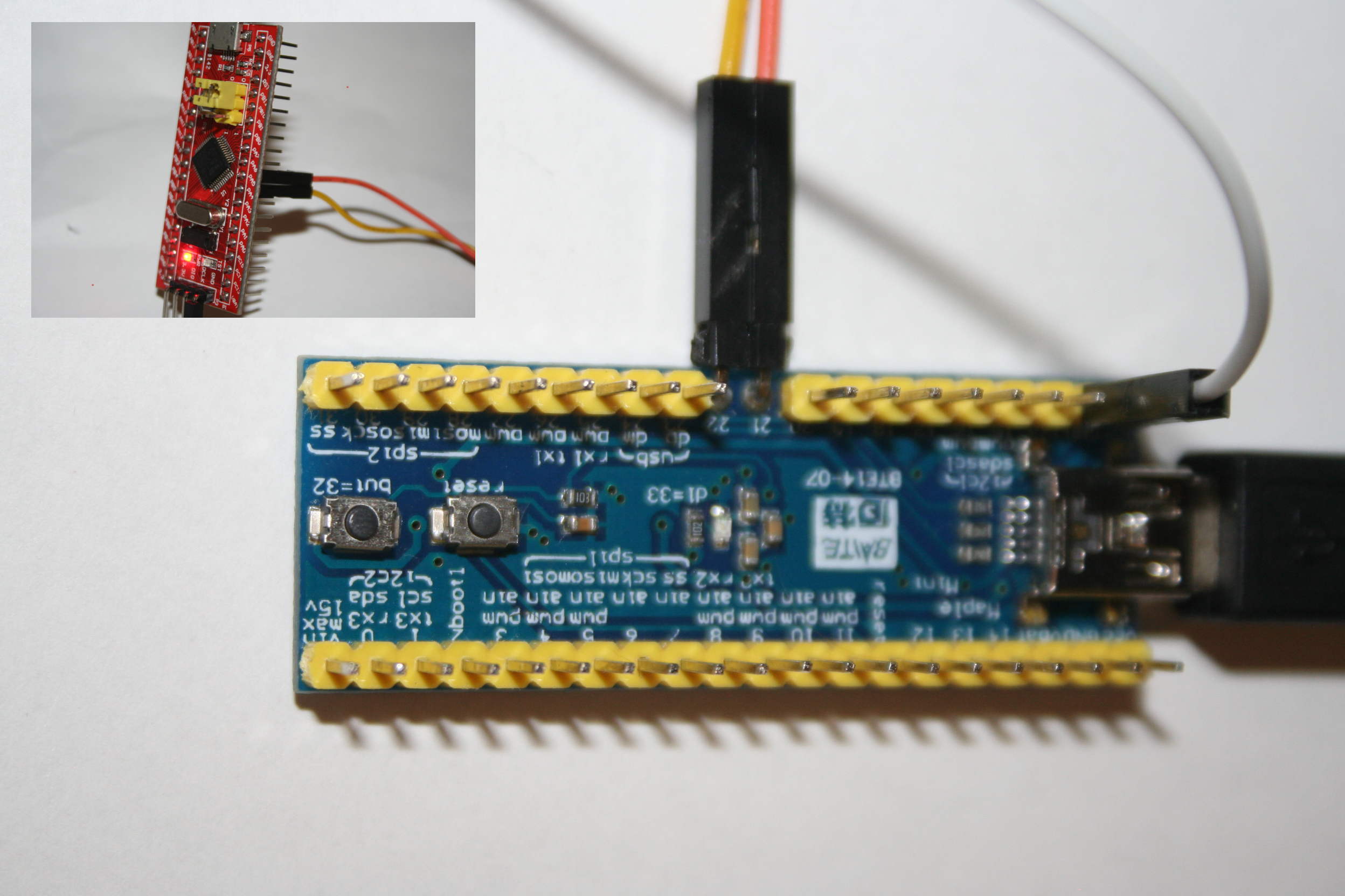
- maple_mini_bmp.jpg (218.33 KiB) Viewed 1114 times
PA13 –> (SWDIO)
PA14 –> (SWCLK)
~Straw
I’m not suggesting this as an option, because I agree that if people choose a BMP STLink upload the debug pins should be enabled…
But, If anyone accidentally uploads code which turns the SWD pins into GPIO, you can still upload by running the stlink upload, and then press reset while its waiting to time out.
Obviously this is a pain for normal development, and I wouldn’t recommend it. But it’s what I used when working on the bootloader, because I needed to test that all the GPIO pins were available for the button or the LED
So you think it is better keeping it as st-link?
I understand with BMP you get a server available as soon as you connect the device, while with st-link you need to run texane.
That is a point in favor of BMP. Is there anything that’s better on st-link?
If you pair your stlink device with openocd, you can use it to flash and program a much wider list of chips. I’ve used the stlink device with NXP LPC1114FN28 chips and LPC8XX, and some stm32f0xx chips just sitting on a pcb. The openocd crew is constantly adding support for new chips and jtag/swd devices. The only problem is you need to get a openocd binary, and this might become less of a problem now that the Arduino Zero is using openocd as its upload.
I’m using linux and openocd, I’ve added support for new chips openocd and new programmers didn’t support. The openocd is fairly well organized and adding support for new things usually just involved adding an entry to a table. Eventually, those chips and devices got supported and I could just use the stock code. The texane stuff, is more a hack when it comes to how they handle a lot of the responses to gdb rsp and devices. Although you can certainly get lost using the openocd vs texane. Texane is simple and openocd is more complex but flexible.
I think you have a lot more choices if you just leave it as a stlink device. But if you only plan to use the BMP device with this port. It certainly removes having to deal with either openocd or texane on the host side. All you need is arm-none-eabi-gdb.
-rick
I’ll just leave it as st-link for the time being.
I just tweaked the speed settings on the SWDIO and SWCLK pins. I lowered it from 50MHz to 10MHz. 50 was working fine with my maple mini clone and my red pill/blue pill boards. However, I tried using this with an old stm32vl discovery board. It was failing intermittently. I lowered the speed and those problems went away. I guess it was driving the slew harder than it needed to.
Those value line discovery boards have some issues. It has an STLink V1 interface and they are a pain on linux, as they try and create a mass storage device and linux has issues with how it is done. The target chip is the stm32f100rbt6, a lower price point version of the cortex-m3. It doesn’t have much going for it though. It only has 8k of RAM and runs at 24MHz max, although I was able to run it at 48MHz and it did seem to work. I guess the only good thing about it is a couple of DAC peripherals, and all of its pins are broken out. Oh and yeah, this board is used in the Indiana University Computer Science course:
http://www.cs.indiana.edu/~geobrown/book.pdf
https://github.com/geoffreymbrown/STM32-Template
I pushed my minor changes to the github source.
-rick
http://www.cs.indiana.edu/~geobrown/book.pdf
https://github.com/geoffreymbrown/STM32-Template
@rick:
Thx for the link.
Ray
So you think it is better keeping it as st-link?
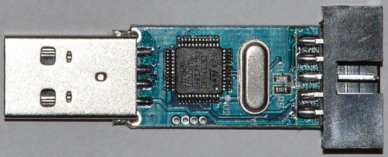
I took a look at the internals and I think the 4 solder pads on the board are for programning it via another Stlink adaptor, as I don’t think they connect to PA9 and PA10 to do a serial upload
If you don’t have another Stlink to program it with, but you have a USB to Serial adaptor, I think you’d need to solder some small wires directly to PA9 and PA10 on the chip, and also put a wire on Boot0
So you think it is better keeping it as st-link?
So you think it is better keeping it as st-link?
I took a look at the internals and I think the 4 solder pads on the board are for programning it via another Stlink adaptor, as I don’t think they connect to PA9 and PA10 to do a serial upload
Its good to have that as reference.
Its good to have that as reference.
i will check
I have two blue pills already. They can be easily turnned into “st-link” just by connect B12 and B14 with a 100Ω resistor, flash st-link fw into it, B13 is SWCLK, B14 is SWDIO. I even made a adapter for it, I also modified the BMP source to use B13 and B14 for SWD, so I can use the same “diy adapter”.
But st-link clones are cheaper than the pills in my universe. Clone is about 13.5 CNY, and blue/red pill is about 20 CNY.
I use BMP mainly for semihosting to get rid of usb-ttl adapter, st-term is alse a choice for me.
Yeah the price in the st-link clones is almost unbeatable, in part because they use STM32F100 rather and F103.
I am sure the BMP firmware can be adapted and flashed to it, but is it worth the trouble having to solder extra wires etc for the small price difference to get a red/blue pill?
I see them in taobao for just 17cny:
https://item.taobao.com/item.htm?spm=a2 … t=4#detail
And there are even better boards for just as cheap:
https://item.taobao.com/item.htm?spm=a2 … t=4#detail
Personally, unless you need a bunch of BMP, and converting the st-link can be done with no soldering at all, I dont think it’s worth the time, you time is probably more valuable used on something else.
I think it would be more fun to load the bootloader onto the stlink ![]()
The LED seems to be on PA9, and there appear to be 4 usable GPIO pins on routed to the connector at the end. I’m not sure if thats enough to do very much. You could connect a I2C periperal to 2 of those pins, or perhaps use them as analog inputs, e.g. some sort of mini data logger etc.
Using stlink as BMP is for tidy.
It very quik to convert the stlink to BMP, no soldering at all, just to make a 2.54 to 1.27 4 pins adapter first (in fact I already have one before for somethings else). Tools can save time.
to victor_pv: Usart is not available, you need to solder to A2 A3, but the good news is they are at corner.
My STLink, which is in the same metal enclosure is a F103.
Re:Alternative software.
I mean use it as an Arduino. Flash the bootloader using another STLink board.
Not you can flash most F103 boards with the STlink binary to make them into an STLink board.
The binary for stlink is on various russian websites ![]()
My STLink, which is in the same metal enclosure is a F103.
I double checked. Both of my are F101’s ![]()
Different boards, one is in the metal case, the other does to have a case
I wonder what the difference is between the F101 and the F103. I know the STLink binary works on the F103 boards, but I suppose that makes sense, as I presume the F103 is a better device than the F101
Edit.
I’ve just looked at the spec on the F101 and one key difference is the clock speed of 36 instead of 72Mhz. I’m not sure if there is anything in the bootloader which would prevent it working on the F101, and of course the core is generally set to 72Mhz, and I’m not sure whether if that value was changed in the core, whether it would work either, as we’ve never tried
Given that the F103’s are so cheap, I guess its hardly worth messing around with getting Arduino etc onto these F101 board (unless they were $1 or something).
Umm.
Does that mean that these F101’s in the STLink adaptors are possibly F103’s ?
They are the same package, I really can’t see how its worth them making the 101 as well as the F103
Umm.
Does that mean that these F101’s in the STLink adaptors are possibly F103’s ?
They are the same package, I really can’t see how its worth them making the 101 as well as the F103
Yes. I read the other day, the clock must be 48Mhz or 72Mhz for usb to work, as the USB clock speed is 48Mhz, and the F103 has 2 divider modes from the main clock, either divide by 1 or divide by 1.5
STLink will connect to the other STLink and reads this data
17:29:31 : Device ID:0x410
17:29:31 : Device flash Size : 128KBytes
17:29:31 : Device family :STM32F10xx Medium-density
However as soon as I try to program the device, STLink has an error and it disconnects.
I’m not sure if this is because both devices are connected to USB, and perhaps it would be better if I disconnect the target board from USB and just use the power and ground from the programmimg STLink, but this seems somewhat unlikely
However I’ll give it a go.
Edit.
OK. When I disconnected the STLink board from USB and powered it from the other STlink board, I was able to program it.
I installed the generic bootloader and the device appeared as a Maple DFU device, and I was able to upload the blinky sketch and which also prints to USB
So the STM32F101 microcontroller seems to work perfectly as a 128k STM32F103CB !
Victor you were soooo right ![]()
The new cheapest Arduino on STM32 looks like its the STLink dongle !
LED is on PA9
Did you manage to read the existing flash before firing on the new program?
Have you thought of any projects that would benefit from the tiny USB dongle form factor?
I presume that this means that at 2.11 GBP (3.29 USD) this is the cheapest stm32duino on ebay… auction prices not withstanding.
With the Blue Pill costing not much more, having a RTC resonator and all the pins broken out for an extra 40 pence makes the StlinkV2 programmer less attractive, except where the project lends itself to the tiny case and low pin count.
However the “because you can” factor means I feel compelled to find some use for the programmer as stm32duino.
I just soldered 2 small wires to my board, which i have now removed, as i can now upload via the bootloader.
I added a “generic-pa9” version to the bootloader to support this board ![]()
So the led on my board now flashes like it should.
Re:Readback
No. It was read locked.
There must be something in the STLink binary which sets the read disabled flag, as even if you download the stlink binary from those russian websites, and flash it into a F103, as soon as it starts running, you are no longer able to read the contents of flash back out.
I suspect it would be easy to hack the binary to prevent it doing this, i.e just look in the binary for the address of the locking register and change it for an address in ram.
That is… unless it checksums its self, but as its updates are uploaded in an encrypted form the devs may not have bothered to do that.
Overall, its not really worth messing around with the Stlink binary, as Black Magic Probe does as least as good a job and is open source.
I don’t really see much use for this board, unless someone had an application for something with very low pin count.
Perhaps a small data logger.
I dont know what pins it uses for its outputs on the connector at the end. I cant seem to find a schematic for the dongle version of the stlink, i can only find diagrams for the stlink on the discovery boards.
Anyway if the pins have analog capabilities, perhaps it could be used as a cheap data logger.
The other thing that this sort of device could be used for is for some basic form of encryption, e.g Rot13, just get the Serial USB to echo back Rot 13 versions of the incomming chars.
Or secure micro storage e.g keep your passwords in it. send the website address in via serial and it looks them up and sends back the username and password for that website.
Re: laser etching a different code.
Ive noticed that its very hard to read the markings on the devices on the stlink dongles.
I had to use a 10x eye glass, and hold it to bright sunlight, and look at an oblique angle to see it was an F101
Its like they made a half hearted attempt to remove the markings already.
Anyway, I guess the thing to do would be to test the RAM size as F101s have either 10 or 16k RAM not 20k, and to see if it has more than one USART, in which case its almost certainly a 103 in disguise ![]()
I dont know what pins it uses for its outputs on the connector at the end. I cant seem to find a schematic for the dongle version of the stlink, i can only find diagrams for the stlink on the discovery boards.
The only official schematics i can find are the ones for the discovery and nucleo boards, but the firmware on the Nucleo stlink is definitely not the same as on the Discovery as it also has USB serial.
I think the stlink software reads some version information and uses this to download the correct binary for the target board.
So i cant really guarantee that the schematics for the Discovery stlink section is the same as the dongle.
I did find this
http://www.micromouseonline.com/wp/wp-c … ink-v2.png
But it doesn’t seem to include the Reset line that the dongle has.
However i could test the Sdio and Sclk pins
The only work order is:
1. Load stlink fw to blue/red pill by usart.
2. Load stlink fw to stlink by “blue/red pill stlink”.
So it’s a litte trouble. Maybe the best way is to buy another stlink.
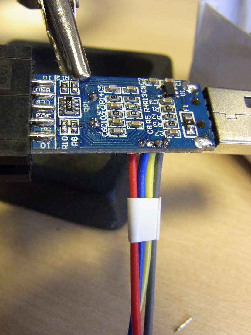
Not perfect, but not bad… It was only once I had finished the job that I realised I probably didn’t need to solder on the 3V3 and GND leads as I can access those signals on the jtag header.
More pictures here if anybody is interested.
Unfortunately since my other ST-Link V2 probe is at home, I can’t probe the probe at the moment.
i stll keep trying to add images with file:///home/stephen…….
stephen
i stll keep trying to add images with file:///home/stephen…….
stephen
Buy I have since installed the bootloader on my aluminium cased one.
GDB has a “restore” command.
https://sourceware.org/gdb/onlinedocs/g … Files.html
(gdb) restore ../STLinkV2.J16.S4.bin
‘../STLinkV2.J16.S4.bin’ is not a recognized file format.
(gdb) restore ../STLinkV2.J16.S4.bin binary
Restoring binary file ../STLinkV2.J16.S4.bin into memory (0x0 to 0x10000)
warning: restore: memory write failed ((undocumented errno -1)).
(gdb) restore ../STLinkV2.J16.S4.bin binary 0x8000000
Restoring binary file ../STLinkV2.J16.S4.bin into memory (0x8000000 to 0x8010000)
Writing to flash memory forbidden in this context
(gdb)
i finally got a sketch running under the debugger with serial output, not entirely sure how:-)
thanks rick.
what i have found is that for anything more than blink (just need to insert #include <Arduino.h> in the cpp file) it gets interesting, mainly with SPI and ‘standard’ definitions(PA4 etc).
i’m using the using-spi-ports example with my additions, heading towards a driving nokia 5110 (my success with adafruit_gfx_as is really, really non stella)
waggles are for my ols.
can anyone list the various headers needed for spi/i2c, the sequence and where they need to go, wrapper or cpp?
so i’m currently relying on the #ifndef’s for blocking a reload of the header files.
i’ve played with various commenting out of the headers. keeping all works, may well be overkill.
stephen
the wrapper is
#include <Arduino.h>

#include <SPI.h>

#include "using_SPI_ports.cpp"
<…>
i’m using the using-spi-ports example with my additions, heading towards a driving nokia 5110 (my success with adafruit_gfx_as is really, really non stella)
<…>
I tried to Flash you BMP binary onto a GD32, but it didnt work.
But now that I think about it….. Its impossibe for it to work because the Xtal is 12Mhz instead of 8Mhz, so all the PLL’s will be wrong for it to enumerate on USB. (The USB prescaler PLL also has 2 bits instead of 1 bit on the STM32)
If I get time, I”ll download all the sources and see if it will Make on my Windows PC (As I make the stm32duino bootloader using my Windows PC, so I should have an equivalent setup)
In the mean time I’ve flashed it onto a STM32 to I can take a look at if it can see the RNF51822
Thanks
Roger
This is probably a really dumb question,but here goes.
If cloned your repo then ran git submodule update to get the libopencm3, however it won’t make because the code can’t find the stm32 directory in libopencm3
I just went into src and then ran make, but possibly because I’m trying to do this on Windows, it seems to have something missing from the path, as it is looking in libopencm3/stm32/…. but the actual structure appears to be libopencm3/lib/stm32/…
Do I need to Make libopencm3 ? (Its not that easy for me to do that as I’d need to sort out the Python stuff on my machine)
Or is there something else I’ve missed?
Thanks.
I’m not sure why I didnt see the top level makefile after I cloned your repo.
I perhaps I was just having a bad day.
OK. I figured out why I didnt run the top level make file… It was because it was using Python, which I didnt have setup for command line usage.
So I’d manually run the git submodule update stuff, but when I ran make on both libopencm3 and the src folder, I’d not included the correct make options as specified in the top level make file.
Anyway. I can now make the code, but the resulting bin doesnt work on my RedPill, but your binary does.
You bin file is 49k but mine is 65k ![]()
I’m using the ARM compiler installed by the Arduino IDE, I just set the Windows PATH ENV to include it.
I’m on the jc66_coreboard branch, and I”m running make from the top level and don’t get any errors.
I guess the first thing I should try and do is recompile on Linux. Can you let me know your setup for gcc on Linux, as although I could use the one from the Arduino IDE, I’d rather use whatever you used, in case this is some sort of library issue
Thanks
Roger
$ arm-none-eabi-gcc --version

arm-none-eabi-gcc (GNU Tools for ARM Embedded Processors) 4.8.4 20140725 (release) [ARM/embedded-4_8-branch revision 213147]
Thanks.
I will try setting the probe host.
I didnt do that before, as it looked like you had created a branch in your repo which defaulted to those files.
But its possible it still effects the build process.
I will let you know how i get on
thanks
roger
Thanks
make PROBE_HOST=jc66_coreboard all
FYI.
I just posted about Arduino on the nRF51822 , being available
However I’m not sure if its reliant on Red Bear hardware
I’ve been going through this thread, but am having some difficulty distilling the answer to that question.
I’ve been going through this thread, but am having some difficulty distilling the answer to that question.
I’ve been going through this thread, but am having some difficulty distilling the answer to that question.
The C8 generic board shown in the posting in the first link is junk. (aka the Ugly board)
I find it unreliable and have given up using it.
I know some people get it to work, but personally i would not recommend it.
@Roger – I’m not sure why that “Ugly Board” is being so, eh, ugly to you. I had one lying around and re-flashing Rick’s build onto it seems to work – well, at least it shows up on USB (on Mac). I did have to change the jumpers: outermost one is towards the corner, but the inner one is away from the board edge.
Now I’m wondering whether PA8/PA9 serial can also be used.
Update – confirmed, this unit seems to work.
Update #2 – serial pass-through also works, on PA2/PA3, as documented.
I know some of them work, but a lot seem to fail to start.
Actually I think the issue is that the HSE clock (external crystal clock ) fails to start first time.
The libmaple core doesn’t include any checks to see if the HSE has started, it just hangs while waiting.
I suspect the BMP code handles this correctly and retries starting then HSE, which then works Ok.
The HSE timeout and restart is on the bottom of a long ToDo list for me ![]()
I’ve adapted Ricks platform.txt gdb commands and removed the STM specific memory reads, and have also manually typed and executed the commands, but with no luck so far.
On Windows I have 2 other issues.
1. The COM port seems to need to be preceded by \\.\ , as described I think in BMPs own wiki
2. On the nrf51, the quit command is not getting executed by gdb, so gdb ends up
locking up the BMP, and the only way to release is to reboot the pc, or to remove the target power or one of the SWD lines.
I will need to see if I have the same issues with quitting when targeting the stm32.
However I’ve no idea why the nrf51 is not getting flashed by the load command.
The bmp is supposed to support the nrf51 series.
BTW. mass erase is not available in the gdb commands for the nrf51, although mass erase is available on the mcu, ( as openocd does it via the. nrf51 mass_erase. command
I dont think the flash is being erased at all, as after Its supposedly flashed and running, I still see the debug messages from the exiting ( different ) sketch. ![]()
Indeed, I’d try this on an F1 first. Perhaps you have to update your BMP to get the latest chip support.
Never a dull moment, eh? 🙂
I will try again on an F1 to prove its not some other problem.
Which could be the case as I’m using a GD32 board, but all I changed was the line in the source that specified it had a 12mhz crystal instead of the 8mhz on the normal SMT32F103 boards.
i.e I’m still running it at 72Mhz and didnt go the whole way and changed the USB prescaler and push it up to 120MHz.
It definitely connected to the F1, and gdb shows all the signs that its working, scan of devices recognizes it as a CortexM0 device etc and attaches OK.
I do get some notices / warnings e.g. cant read target voltage, and a few other messages, but I get the same sort of thing using OpenOCD and an STLink adaptor to flash the same module, and it does flash OK with STLink.
I guess I could try running the Texane STLink server and see if GDB can flash using that method, but I’d really like to use the BMP as it provides serial as well as SWD, and also its self contained, i.e you don’t additionally need the OpenOCD binaries ( and as yet I cant find a way to script OpenOCD to do the upload unless I pipe a script in via Telnet ( which gets very messy)
As I rebuilt from your github sources less than a week ago ( so I could use the GD32) it should all be up to date with the nRF51 stuff, but I guess I could post an issue / question on the main blacksphere repo to see if there are any known nrf51 issues.
(gdb) tar ext /dev/cu.usbmodemD5D4C5E1

Remote debugging using /dev/cu.usbmodemD5D4C5E1

(gdb) mon swdp

Target voltage: Not Implemented!

Available Targets:

No. Att Driver

1      STM32F1 medium density

(gdb) at 1

Attaching to Remote target

0x080013ac in ?? ()

(gdb) mon help

General commands:

version -- Display firmware version info

help -- Display help for monitor commands

jtag_scan -- Scan JTAG chain for devices

swdp_scan -- Scan SW-DP for devices

targets -- Display list of available targets

morse -- Display morse error message

connect_srst -- Configure connect under SRST: (enable|disable)

ARM Cortex-M specific commands:

vector_catch -- Catch exception vectors

STM32 LD/MD specific commands:

erase_mass -- Erase entire flash memory

option -- Manipulate option bytes

(gdb)
No worries.
I just modified the STM32 upload pattern, and just removed the code that displayed the memory locations, and to solve the COM issue i had with the double digit COM port issue
tools.bmp_upload.upload.pattern="{path}{cmd}" -cd "{build.path}" -b {upload.speed} {upload.verbose} -ex "set debug remote 0" -ex "set target-async off" -ex "set remotetimeout 60" -ex "set mem inaccessible-by-default off" -ex "set confirm off" -ex "set height 0" -ex "target extended-remote \\.\{serial.port}" -ex "monitor swdp_scan" -ex "attach 1" -ex "file {build.project_name}.elf" -ex "load" -ex "tbreak main" -ex "run" -ex "echo \n\n\nUpload finished!" -ex "quit"
0.) launch arm-none-eabi-gdb
1.) Connect .. make sure you are connected
target extended-remote \\.COM9
monitor swdp_scan
attach 1
2.) Examine memory where you expect to write
(gdb) x/4x 0x20000000
look to see if the memory where you are going to write, address 0x20000000 in the case above, is empty (0xffffffff)
3.) Try erasing memory
(gdb) monitor erase_mass
go back to step 2 and see if it is erased
Turning it up to 11 might be a little too adventurous to start with.
-rick
But I’ll try again just be sure
I’m sure that didnt work last time I tried it
Perhaps it doesnt know its an nRF51
How do I tell GDB what process it is, perhaps the version info in the chips don’t match what BMP / GDB expect ? I know there are multiple versions of nRF51 though I’m not sure what the AAxx letters at the end of the part number actually mean.
GNU gdb (GNU Tools for ARM Embedded Processors) 7.6.0.20140228-cvs

Copyright (C) 2013 Free Software Foundation, Inc.

License GPLv3+: GNU GPL version 3 or later <http://gnu.org/licenses/gpl.html>

This is free software: you are free to change and redistribute it.

There is NO WARRANTY, to the extent permitted by law.  Type "show copying"

and "show warranty" for details.

This GDB was configured as "--host=i686-w64-mingw32 --target=arm-none-eabi".

For bug reporting instructions, please see:

<http://www.gnu.org/software/gdb/bugs/>.

(gdb) target extended-remote \\.\COM38

Remote debugging using \\.\COM38

(gdb) monitor swdp_scan

Target voltage: Not Implemented!

Available Targets:

No. Att Driver

1      ARM Cortex-M

(gdb) attach 1

Attaching to Remote target

warning: while parsing target memory map (at line 1): Required element <memory> is missing

0x00002fa0 in ?? ()

(gdb) monitor mass_erase

Target does not support this command.

(gdb)
In the case of the “S130” Softdevice, that address seems to be 0x1C00 (the S110 Softdevice is smaller, but the code I’m currently using, is pseudo linking against the S130 sofdevice / library)
From what I’d read about the BMP, the “load” command was suppose to pre-erase the pages necessary, before flashing.
However I suspect if it doesnt know its an nRF51 that none of this stuff is happening
As a matter of interested, I looked at 0x1c00
(gdb) x/4x 0x1c000

0x1c000:        0x20004000      0x0001c789      0x0001c7c5      0x0001c7c7
How do I tell GDB what process it is, perhaps the version info in the chips don’t match what BMP / GDB expect ? I know there are multiple versions of nRF51 though I’m not sure what the AAxx letters at the end of the part number actually mean.
Or give me a couple of days and I should have the carrier board and I can connect up my own and figure it out:
http://i66.tinypic.com/20az9yh.jpg
* you could also use 2 BMP devices to figure this out, one debugging the other.
I actually just looked an it seems that the device ID register is at 0x1000005c
https://devzone.nordicsemi.com/question … gh-segger/
and in the BMP code this seems to be just shown as 0x5C so I guess they are the same
anyway, reading that address gives
(gdb) x/4x 0x1000005c

0x1000005c:     0xffff0084      0xa1ff477e      0xfdf8eecc      0xffffffff

(gdb)
It seems to have QFACAA printed on it
I think both the modules i have, are contain the same chip
I have ordered a motherboard, and it comes with another module board (well I chose to buy a motherboard that came with a module so that I’d have 3 of them)
I’ve actually found some cheaper modules, which would be more practical to use in actual real world scenarios, and which are a bit cheaper
http://www.aliexpress.com/item/10pcs-lo … 69314.html
But for dev they would need a breakout board
I was just about to post this
target_add_ram(t, 0x20000000, 0x8000);
But I’ll see what you did ![]()
I pulled your changes
I thought it was 32k ram ???
Not that it will affect the upload
Made and flashed it but forgot to set
PROBE_HOST=jc66_coreboard all
So USB didnt work
So I’ll have to reconnect it all and reflash it again
PS. It a rare event but I”ve turned on IRC ![]()
Some progress
Its now recognised as the NRF51
(gdb) monitor swdp_scan

Target voltage: Not Implemented!

Available Targets:

No. Att Driver

1      Nordic nRF51

(gdb) attach 1

Attaching to Remote target

0x00002fa0 in ?? ()
(gdb) help restore
Restore the contents of FILE to target memory.
Arguments are FILE OFFSET START END where all except FILE are optional.
OFFSET will be added to the base address of the file (default zero).
If START and END are given, only the file contents within that range
(file relative) will be restored to target memory.
So …
(gdb) restore blink.hex
Command is erase_mass not mass_erase
Sorry, its my dyslexia (well kind of, as I’m not really dyslexic )
I’ll see if it gets erased
Edit
address 0 seem to have ffff
Seems to load the ELF file OK and the memory at 0x01c000 seems to look like the start of the bin file that was also created by the IDE
Ah.
Looks like it is kind of working.
If I manually load the SoftDevice and then manually load the sketch
I’ll try changing the sketch
Edit. Just to close off this chapter…
The latest BMP code in Rick’s repo worked with my nRF51822 (32k) device !
2 things really
(a) BMP on Maple mini.
Any ideas on if its that invasive to change the code so that it uses the Maple hardware to reset the USB ?
(Actually I don’t know how you did it on the Blue Pill, I presume you used the GPIO USB D+ method
(b) Following on from (a)….
If we can run it on the Maple mini, I presume we can change the Vector table address and also the loader file and load the BMP via DFU into a Maple mini while still retaining the bootloader.
i.e Have this for an option for people who are not comfortable with flashing their Maple mini over to BMP using external USB to serial etc.
Either way. I think adding support for the Maple mini board would be a benefit as the Maple mini boards are physically much more robust than the Blue Pill.
Personally I don’t buy Blue Pills any more, I’d rather spend the extra couple of dollars and have a better made more reliable board.
One minor annoyance, which I don’t know if it occurs on the STM32
If I disconnect the BMP (connected to the NRF51) and reconnect.
The default condition seems to be that the BMP halts the nRF51. The only way to get it to run without uploading again, is to pull one of the SWD wires off.
Even if I reconnect or power cycle the nRF51 (but removing its power wire from the BMP), it still goes into halt ![]()
I’ve not disconnected it and connected it to a STM32, so I don’t know if it does the same thing, but either way, I probably need to modify it, so it doesn’t default to halting the processor like this.
I think I have fixed my issue of the target board being halted on powerup.
If I change the code so that the SWD and SDIO pins are not driven low in the platform_init code e.g. change _clear to _set
like this
	/* Setup GPIO ports */

gpio_set_mode(SWDIO_PORT, GPIO_MODE_OUTPUT_10_MHZ,

GPIO_CNF_OUTPUT_PUSHPULL, SWDIO_PIN);

gpio_set(SWDIO_PORT,SWDIO_PIN);
gpio_set_mode(SWCLK_PORT, GPIO_MODE_OUTPUT_10_MHZ,
GPIO_CNF_OUTPUT_PUSHPULL, SWCLK_PIN);
gpio_set(SWCLK_PORT,SWCLK_PIN);
gpio_set_mode(LED_PORT, GPIO_MODE_OUTPUT_2_MHZ,
GPIO_CNF_OUTPUT_PUSHPULL, LED_IDLE_RUN);
There’s also a “detach” command in gdb, perhaps that’s of use?
BTW, I’m using this with various non-Maple-Mini boards.
I need to some more investigation, but I think its just one of the pins being LOW is halting the core, At the moment I just Set them both and that fixes it.
Just leaving them in their default state was no good, they definitely needed to be set High.
But I have no knowledge about how SWD works.
I presume that the programmer provides the clock signal, and the SDIO is bi directional.
I will see if I can find a simple explanation of SWD on ARM
…
But I have no knowledge about how SWD works.
I presume that the programmer provides the clock signal, and the SDIO is bi directional.
I will see if I can find a simple explanation of SWD on ARM
No worries about the j66_coreboard.
I did wonder where it came from, as i noticed it wasn’t in the Master repo as far as i could tell.
Perhaps for the GD32 and maple mini, I should copy your j66 folder and make changes, rather than trying to put #ifdef s in the j66 platform
Or even fork off the upstream.
Or even fork off the upstream.
Or even fork off the upstream.
Ok..
![]()
Why did you “clear” both SWD pins in the init () ??
I took a look at the stlink files and they don’t seem to clear those bits.
Actually they don’t clear them either, so I suspect the default state is LOW, but I’d need to double check.
Set’ing those bits seems to fix things for me, so I think I’ll leave it like that
But I’ll clone off blacksphere’s repo, then add you j66 coreboard as GD32F103_120Mhz – with my changes, and also make Maple mini version and a generic stm32f103c version (very similar to your j66)
I’ll credit you in the comments.
I also want to add a binaries folder to the repo. I’m not sure if this is politically correct for github, but a lot of projects have hex files etc for download in the repo.
If I remove them the nRF51 still seems to go into halt on power up.
I actively need to set them
I’m not sure what the default input state is on the SWD pins on the nRF51, if they are not connected, I suspect that both pins just float.
However I’m not sure if they float high or just float.
I suspect they must have some sort of pull up of pull down on them, otherwise the SWClock will get noise pickup and it may think its being clocked with random data, which sounds like a recipe for unreliable start-up’s
Edit.
https://devzone.nordicsemi.com/question … resistors/
Strange.
They seem to say that both pins are OK in a default state of being pulled down. However, If the BMP “clears” both, the module goes into debug mode.
From the posting on Nordic’s site there seems to be some differences between which revision of the chip is being used, but they all seem to need to default to being LOW; either with internal or external.
But its strange if I do this using the BMP there seems to be a problem with this.
I’ll need to try just pulling those lines low using resistors and see if it has the same effect, as I wonder if its caused because the platform init() is being caused some time after powerup.
I’ll probably need to stick my scope / logic analyser on it.
I posted a follow up to the other Offtopic nRF thread.
It appears that SWDIO on the nRf51 doubles up as the Reset pin.
Rick. If you look on your nRf motherboard, the button marked Reset appears to connects / shorts SWDIO to Gnd when you press it.
I’m still waiting for my motherboard ;-(
Great work on the diy BMP! That is a handy tool.
I’ve had good luck using a Blue Pill and the pre-complied binary: downloading sketches works fine, also gdb works as described.
The only hardware modification was replacing the 10k (R10) pullup with 1.5K.
Was wondering what additional features are in the latest git sources?
I managed to build a new BMP bin file after fixing paths to the ARM toolchain resulting 65,604 byte binary.
The pre-compiled binary was 50,096 bytes.
Does that sound reasonable?
Thanks for all the efforts.
If you binary is over 64k (which I think it now is), then technically it won’t fit in a stm32f103c8 however in reality most of the chips labelled as stm32103C8 are actually the stm32f103CB i.e the larger flash version.
So I think you should be OK even if it is that size
I’d just give it a try and if its no good, reflash back to the precompiled version ![]()
With thanks to @rick for creating and sharing his BMP build.
The changes are very minor, you just change the USB reset stuff to use a different pin, and swap the Set and Clear calls around the other way, and you don’t need the delay loop.
I will put the new ‘platform’ in my clone of blacksphere’s repo, but I need to push just the NRF51 changes first as I want to do a PR back to blacksphere’s repo just for the nRF51 stuff.
I was hoping to do a version of the BMP which I could relocate to run from 0x8005000 so it couldnt be installed on a Maple mini via the bootloader, but the base address in libopencm3 doesnt seem easy to change, as it appears to be defined in lots of places, and I didnt want a custom version of libopencm3 in my BMP repo.
RogerClark wrote:[…] the base address in libopencm3 doesnt seem easy to change, as it appears to be defined in lots of places
This might be of use: https://github.com/blacksphere/blackmag … inc#L9-L13
Interesting link…
I will need to check the libopncm3 code on my machine
I searched the current github repo version and I cant find 0x800000 in the source, but I am fairly sure its in the version I am using for the BMP ( but I will need to double check)
Umm hang in, i will find what version it us and search github ![]()
Edit.
I meed so search in my codebase as i cant see in it blackspheres version either.
ummm. very strange.. I may be talking rubbish.
Edit
OK.
I was not going totally mad.
The base address for STM32 is defined inside libopencm3 (at least the version that the Blacksphere’s repo uses)
See this search
https://github.com/libopencm3/libopencm … x08000000U
So… It could be changed, but, you’d need to change stuff inside libopencm3
I’ve just check again, and even the most recent version of openlibcm3 has this hard coded into the stm32f1 device
So as far as I can tell, you’re going to need to fork openlibcm3 and modify it, then you’ll need to detach the libopencm3 submodule from your code (if you have attached a submodule) and attach your fork of openlibcm3 which has the base address changed in a few places.
(actually its a shame that the name is not displayed on either windows or OSX)
On Mac OSX, the gdb port’s name always end in “1”, serial pass-through always ends in “3”.
Yes. Thats what I was trying to ask
Unfortunately on Windows its not so clear as they just have 2 different COM numbers and I think it matters which order you install the drivers which around the 2 comm numbers are assigned
I’m looking for a super-easy, beginner’s flasher for my Arduino-on-nRF51822 project.
So that means:
- – very cheap (£10/$15 say)
– very easily sourced (so Adafruit ideally)
– no flasher needed to create the flasher! (so already flashed, software-driven or flashable through serial)
I’ve been playing with ST-Link/V2+OpenOCD, which already meets these requirements, and have pre-ordered an IBDAP and some FT232H boards, both of which could also meet them, along with OpenOCD.
But I discovered BMP through your own Arduino-on-nRF51822 article
http://www.rogerclark.net/arduino-on-th … ontroller/
and this gives us two significant bonuses:
- – the GDB connection
– the Serial connection
Which brings me back to the above requirements list, and a list of questions about STM32F103-based boards – which I’m hoping you’ll kindly answer.. ![]()
Option 1 – re-purpose an ST-Link/V2 mini:
- – can I use something like the ST firmware upgrader to re-flash an ST-Link/V2 mini through USB?
– or somehow through Serial like you did? (I believe they have SWD pads, but that’s the circular problem)
Option 2 – commodity STM32F103 boards:
- – what is this ‘red pill’ / ‘blue pill’ thing all about?
 are these essentially Maple Minis?
– can they all be flashed through serial or is the one you used (which you said was a Maple Mini) special?
– are they only available from China? I see local UK suppliers, but I’m not sure what I’m getting
I’d also love to see a photo of (a) your board being flashed through serial, and (b) your board all wired up to the target! I find pictures make it easier for me to understand what’s going on!
Hope that’s not too much to ask for a first posting to this forum!
Cheers!
Duncan
It is possible to put the BMP onto a STLink dongle, but there are reasons why this is not ideal…
STLink dongles do not break out the Serial port pins (PA9 and PA10) and solderimg to the STM32 is challenging
You cant use the STLink updated progam by STM to update to BMP, you have to flash using another STLink.
So I would keep your STlink to program other STM32 and STM8 boards
Re:Blue Pill etc
This is the name someone coined for the cheap generic STM32F103C8 boards that are easily available on eBay. They are a bit like an Arduino Nano, just a bit longer.
But a better option is the Maple mini, which is the same size but is well made and has the 128k flash F103CB chip
Im not sure who sells STM32 boards apart from the eBay and Aliexpress vendors, but if you want local stock, just look on ebay for a local supplier of the Maple Mini board
Once you have the Maple mini or the blue pill etc, you can flash the bmp using your stlink
BTW. I added Segger JLink as an upload option, and Jlink compatible programmers are available farily cheaply on eBay, and the home / educational version from Segger is not too expensive, But both options are more expensive than using a Maple mini.
I’m currently using Jlink, but may go back to BMP, as I have some wierd things going on with a WT51822-S2 module that I’m trying to use.
The most reliable modules to start with, seem to be the development motherboard and modules from WaveShare. They all work fine for me ( both the QFAC and QFAA device types ).
BTW. I dont have any QFAB modules as they are only 128k flash and the S130 Softdevice takes 109k, and user code starts at 112k, which does not leave enough room for a user application that actually uses the Softdevice.
Sad that the ST-Link/V2 can’t be flashed by serial – or rather, we haven’t managed to work out how ST do it with their upgrade tool through USB!
So I want the users of my project to be able to easily buy a board and download BMP to it via serial – but I don’t know where I’d point them to find a board – they could either pick up a Maple Mini clone or one of the red/blue boards it seems? Could you provide links to definitive examples of each to get me started – I may have to just buy one of each and try it myself.. ![]()
Do the red/blue boards support serial flashing on PA9/10 like the Maple? I found this article on your site, which implies that they do:
http://www.rogerclark.net/stm32f103-and … 1-5-x-ide/
Is that a ‘blue pill’, then?
Cheers!
Duncan
Most STM32 board support flashing via serial. The serial bootloader is built into the hardware of the F103 chip
The only reason that its hard to flash the STLink dongles is that the pins for PA9 and PA10 and also for Boot0 are hard to get to, as they are not broken out onto a pad or pin
The STLink dongles generally have the SWD (SWDIO and SWCLK) pins plus power and ground, connected to 4 small pads on the dongle, so that its possible for mere mortals to solder onto the pads, and connect another STLink (or BMP etc) and program them
If you are good at soldering it would be possible to solder directly onto pins PA9 and PA10 and Boot0 on the chip and connect a USB to serial adaptor and also to set Boot0 HIGH (you may also need to set Boot1 low, as this may be floating – I can’t remember if the STLink dongles bother to tie this low as Boot1 only makes a difference when Boot1 is HIGH)
The Blue and Red Pill are basically the forums’ names for the board you found on my blog (http://www.rogerclark.net/stm32f103-and … 1-5-x-ide/)
e.g you can get them on ebay for a few pounds.
This is an example on eBay, but you may find cheaper or want to get from a local supplier
http://www.ebay.co.uk/itm/STM32F103C8T6 … Sw6aVUo1Pq
For the Maple mini, I forget precisely which thread its in, but most people buy them from a company called “Baite” as they actually manufacture the boards, and hence you get ones which have passed their QA process.
Often Maple Mini’s from other suppliers are actually Baite reject boards that have been reflow soldered to fix dry joints.
And I think perhaps there are other manufacturers..
@mrburnette is the Maple mini supply expert
But any STM32F103 board should technically be capable of being flashed with the BMP firmware via Serial
I have versions for the Blue / Red pill as well as the Maple mini (which has different USB reset hardware), and also the GD32 (like the STM32 but faster) (but the GD32 boards normally have a 12Mhz crystal instead of an 8Mhz on the STM32 – though this is not why the GD32 is faster, as the master clock frequencies for them both is still 72Mhz)
price is similar.
i’d suggest you get a Baites 5 off set, go to their store and search for ‘STM32’, pricing is almost the same per unit as a singleton, single postage though.
i don’t think i’ve killed a single 103c8t6 as yet, but definitely a zet6 with 12v and not any of the pills i have, similar comment as to purchasing them.
stephen
Yes, you may find some $0.50 less. However, my belief is to build a relationship with a vendor who has consistently providedme with excellent product – out of 40+ devices, 100% satisfied. Ss they say, your results msy vary.
Warning: Chinese New Year is next month – almost all of China will be on vacation. Expect delays.
Ray
Could I ask a couple more questions..? On USB flashing – which I have just realised may be an option instead of PA9/10/Boot0 or SWD.
I believe Maple clones can be flashed over USB, but you (Roger) didn’t suggest that approach in your article: http://www.rogerclark.net/arduino-on-th … ontroller/ – was there a reason for that?
I presume there’s no hope of flashing a Red/Blue board over USB?
As we know, ST-Links can be upgraded over USB (http://www.st.com/web/en/catalog/tools/PF258194), so has anyone looked around the ST Java code to see how to do generic flashing? I poked around and saw AES encryption in there, so maybe they’ve got some kind of protection guff.
Finally, if you did flash BMP onto an ST-Link mini, using any approach, do you think you could use the non-SWD pins (marked RST and SWM on my board) as the serial connection, if BMP were re-built accordingly?
Apologies if all this is out there and I shoulda known it! ![]()
Cheers!
Duncan
The STM32F103 does not have a built in USB upload feature built into the chip (the STM32F4 series does but not the F1 series)
Normally when we program the Maple mini and the generic STM32F103 boards using the Arduino IDE, we use the STM32duino-bootloader
(This is updated version of the original Maple-bootloder written by Leaflabs)
The bootloader comes pre-installed on Maple mini boards and can be flashed onto generic STM32 boards (e.g. Blue Pill), and then remains resident and provides the upload / reflashing via USB.
i.e when you power on the Maple mini it runs the bootloader code in the base of flash which enumarates on USB as a DFU device for about 1 second.
If the host PC does not start sending data to the DFU device in about the first second after booting, the bootloader looks to see if there is any code at the sketch start address 0x8002000 and if so it jumps to that address and the sketch starts to run.
In order to get the BMP to work in this way, it would need to be compiled so that the base address of the code is 0x8002000 instead of the start of flash (which is 0x800000)
I did briefly look at doing this, but the code that would need to be changed seems to be deep inside libcm3 and it looked like it would take quite some time to modify, test and debug.
So as there was very little gain in doing this apart from allowing Maple mini users to run the BMP as if it was a sketch, I didnt feel it was worth me spending any of my very limited time on doing that as an option.
Re: Repurposing some of the pins on the STlink as Serial
Its a nice idea, but I’m not sure whether it would be possible
Although the STM32F103 has multiple USARTS, I’m not sure if any of them are on the pins use by RESET and SWIM
You’d need to find a schematic for the STLink stick and find which pins are used (I think one of them my be PB0), you’d then need to check if any of them are USART pins.
If they are not primary USART pins, there are remap / alternative pins for the USARTS, so you need to check that as well
If they are remap pins, in theory you could modify the BMP code to remap the pins and use the appropriate USART.
However the pins may not be both on the same USART
I suspect you are making yourself a huge amount of work.
flashing a pill for bmp install is easy, it’s puzzled me or i was unsure and then it was so simple i posted a comment to that effect.
istr 2 photo’s from a rick thread, combining them shows all 4 wires that will connected to the target, programming it is
via 4 pins on end of the pill. careful pin counting is reccomended. also there is a link to a binary zip you can install, beginning of the thread and it gets updated.
after that it gets interesting and maybe a tad confusing for my braincell. openocd is suggested. using it is not a gui.
stephen
Rick Kimball wrote:Darius wrote:Hi all,
I’m just trying out STM32Duino and so I cloned https://github.com/rogerclarkmelbourne/ … _STM32.git and checked out the development branch.
I twiddled STM32F1/platform.txt to change ‘runtime.tools.arm-none-eabi-gcc.path’ to point to my build environment.
https://github.com/rogerclarkmelbourne/ … stallation
Step 2:
Run the IDE, and on the Tools menu, select the Boards manager, and install the Arduino Due from the list of available boards.
*NOTE: this step installed the arm-none-eabi-g++
https://github.com/rogerclarkmelbourne/ … stallation
Step 2:
Run the IDE, and on the Tools menu, select the Boards manager, and install the Arduino Due from the list of available boards.
*NOTE: this step installed the arm-none-eabi-g++
‘STM32 ST-LINK Utility’ is needed for convert .bin to .hex, I tried to use arm-none-eabi-objcopy for convertion but failed.
$ arm-none-eabi-gdb -batch -ex 'tar ext COM3' -ex 'mon ver' -ex 'mon sw' -ex 'at 1' -ex 'mon option erase' -ex 'load x.hex'

Black Magic Probe (Firmware xxx) (Hardware Version 1)

Copyright (C) 2015  Black Sphere Technologies Ltd.

License GPLv3+: GNU GPL version 3 or later <http://gnu.org/licenses/gpl.html>
Target voltage: Not Implemented!

Available Targets:

No. Att Driver

1      STM32F1 medium density

0x0800cc98 in ?? ()

0x1FFFF800: 0x5AA5

0x1FFFF802: 0xFFFF

0x1FFFF804: 0xFFFF

0x1FFFF806: 0xFFFF

0x1FFFF808: 0xFFFF

0x1FFFF80A: 0xFFFF

0x1FFFF80C: 0xFFFF

0x1FFFF80E: 0xFFFF

Loading section .sec1, size 0x2000 lma 0x8000000

Loading section .sec2, size 0x2000 lma 0x8002000

Loading section .sec3, size 0x2000 lma 0x8004000

Loading section .sec4, size 0x2000 lma 0x8006000

Loading section .sec5, size 0x2000 lma 0x8008000

Loading section .sec6, size 0x2000 lma 0x800a000

Loading section .sec7, size 0x2000 lma 0x800c000

Loading section .sec8, size 0x318 lma 0x800e000

Start address 0x0, load size 58136
Try using the Export Compiled Binary menu option on the Sketch menu
Try using the Export Compiled Binary menu option on the Sketch menu
This is only for closed source firmware.
I’ve seen suggestions about using the cheapest blue pill anyway I have a concern on this: blue pills (and newer black pills – viewtopic.php?f=28&t=117&start=170#p18316) have a quite low power LDO so:
- Would the blue pill LDO be enough to power up the target board, upload and debug at least non power demanding sketches?
- In case the power provided by the blue pill based BMP is not enough, how else should I power the target board?
- Could it be better to use a board which features a AMS1117?!
Thanks in advance and bye, E.
Side questions for who have both the blue pill and the new black pill: which one would you suggest and why?
-rick
-rick
1) Flash BMP FW into st-link using the second st-link dongle
2) Flash BMP FW into blue stm32F103c8t6 board
1) Flash BMP FW into st-link using the second st-link dongle
2) Flash BMP FW into blue stm32F103c8t6 board
1) Flash BMP FW into st-link using the second st-link dongle
2) Flash BMP FW into blue stm32F103c8t6 board
I tried to compile and flash the latest version of the BMP onto a STLink made by Baite ( the same company that sell the Maple mini clones)
But it doesn’t work at all. ( USB is not working)
I do have an old version of the BMP that works in those STLinks, which is based on Ricks BluePill port of the BMP.
But the BMP core code has changed a lot since Rick did has BluePill version, so its not possible to simply copy the platform files for the Baite STLink into the new code.
And at the moment I don’t have the time to bring the old code up to date, so I’m continuing to use the old version.
In the longer term however I was intending to do a Baite STLink “platform” and submit it as a PR.
However as Gareth is now doing a commercial push for to sell the BMP via kickstarter, I have a concern that doing this would allow Baite to bring out a $3 BMP, as they already use the same hardware has another programmer as well as a STLink, and it would be incredibly easy for them to drastically undercut Gareths price.
I’ll try latest stlink binary and see how it works on bluepill.
i would be surprised if it runs on the Blue Pill if it doesnt work on the Baite STLink as the Baite STLink is basically the same as the BluePill, just with much less GPIO.
Actually, after saying that… I guess i should look at the schematic for a STLink dongle vs a STLink on a Nucleo, as AFIK the BMP code is designed to run on a Nucleo or Discovery STLink and the USB enumeration reset circuit may be different between those 2 types of board.
EDIT: found these from platform.h
* TMS = PA4 (input for SWDP)
Paypal link seems to be working again now. Perhaps it was an issue with paypal
can you try it again
Re: BMP not working on the Baite STLink dongle
ummm..
OK. I’m not sure what the difference is between the dongle and the Nucleo / Discovery hardware but perhaps it doesnt work on either at the moment
I don’t want to reflash any of my Nucleos as there is no way to get back to the version of stlink that uses USB mass storage and also has USB Serial ( as that binary has never been hacked and released)
But I think my Discovery F4 board doesnt have the mass storage, so I guess I could blow that away, but I’d loose USB serial so I could not go back to the original config by loading the hacked version of stlinks for the dongle
Re:Donations
Unfortunately if I accept donations, as it will almost certainly cause problems for me.
I provide the code etc, “as is”. I don’t make any guarantees that things work or that I will fix bugs.. As I simply don’t have time.
I’m sure that if I added a Donate button, that some people would make a donation and then expect some bug to be fixed in return.
I already get loads of unsolicited emails asking me for help with various projects. I used to respond politely saying that I can’t give individual help via email.
But I have received abusive emails when I’ve done that, so I simply do not reply to unsolicited emails any more.
Also. I’m sure the Australian Tax Office would tell me that “donations” were payment for services and hence taxable, and I’d need to individually account for each one, and declare them as part of the Business Activity Statement I have to do every 3 months
So the admin time involved would also make it not worth the hassle.
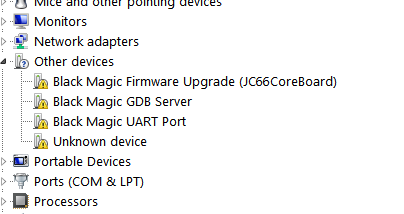
Edit: found
http://www.blacksphere.co.nz/downloads/driver.w32.zip
Hmm.. these drivers don’t seem to work and install
# I copied the src/platforms/stlink to src/platforms/bluepill

# then in the BMP/src directory:

$ git status

On branch master

Your branch is up-to-date with 'origin/master'.

Changes not staged for commit:

(use "git add <file>..." to update what will be committed)

(use "git checkout -- <file>..." to discard changes in working directory)
modified: Makefile
Untracked files:
(use "git add <file>..." to include in what will be committed)
platforms/bluepill/
no changes added to commit (use "git add" and/or "git commit -a")
$ git diff
diff --git a/src/Makefile b/src/Makefile
index 8bc2659..55bc99e 100644
--- a/src/Makefile
+++ b/src/Makefile
@@ -108,6 +108,6 @@ all_platforms:
include/version.h: FORCE
$(Q)echo " GIT include/version.h"
- $(Q)echo "#define FIRMWARE_VERSION \"`git describe --always --dirty`\"" > $@
+ $(Q)echo "#define FIRMWARE_VERSION \"`git describe --always --dirty`-rk\"" > $@
-include *.d
$ diff platforms/bluepill platforms/stlink
diff platforms/bluepill/Makefile.inc platforms/stlink/Makefile.inc
14c14
< LDFLAGS = $(LDFLAGS_BOOT) -Wl,-Ttext=0x8000000
---
> LDFLAGS = $(LDFLAGS_BOOT) -Wl,-Ttext=0x8002000
24c24
< .phony: install all host_clean
---
> all: blackmagic.bin blackmagic_dfu.bin blackmagic_dfu.hex dfu_upgrade.bin dfu_upgrade.hex
26c26,32
< all: blackmagic.bin
---
> blackmagic_dfu: usbdfu.o dfucore.o dfu_f1.o
> @echo " LD $@"
> $(Q)$(CC) $^ -o $@ $(LDFLAGS_BOOT)
>
> dfu_upgrade: dfu_upgrade.o dfucore.o dfu_f1.o
> @echo " LD $@"
> $(Q)$(CC) $^ -o $@ $(LDFLAGS)
31,32d36
< install:
< openocd -f ~/openocd_cfg/st_nucleo_f103rb.cfg -c 'program blackmagic verify reset exit'
diff platforms/bluepill/platform.c platforms/stlink/platform.c
104c104
< //SCB_VTOR = 0x2000; /* Relocate interrupt vector table here */
---
> SCB_VTOR = 0x2000; /* Relocate interrupt vector table here */
diff platforms/bluepill/platform.h platforms/stlink/platform.h
66c66
< #define TMS_PORT GPIOA
---
> #define TMS_PORT GPIOB
70c70
< #define TMS_PIN GPIO4
---
> #define TMS_PIN GPIO14
$ make PROBE_HOST=bluepill clean all install
I’m not sure if these are the same file but…
Try
# I copied the src/platforms/stlink to src/platforms/bluepill

# in the BMP/src directory:

$ git status

On branch master

Your branch is up-to-date with 'origin/master'.

Changes not staged for commit:

(use "git add <file>..." to update what will be committed)

(use "git checkout -- <file>..." to discard changes in working directory)
modified: Makefile
Untracked files:
(use "git add <file>..." to include in what will be committed)
platforms/bluepill/
no changes added to commit (use "git add" and/or "git commit -a")
$ git diff
diff --git a/src/Makefile b/src/Makefile
index 8bc2659..55bc99e 100644
--- a/src/Makefile
+++ b/src/Makefile
@@ -108,6 +108,6 @@ all_platforms:
include/version.h: FORCE
$(Q)echo " GIT include/version.h"
- $(Q)echo "#define FIRMWARE_VERSION \"`git describe --always --dirty`\"" > $@
+ $(Q)echo "#define FIRMWARE_VERSION \"`git describe --always --dirty`-rk\"" > $@
-include *.d
$ diff platforms/bluepill platforms/stlink
diff platforms/bluepill/Makefile.inc platforms/stlink/Makefile.inc
14c14
< LDFLAGS = $(LDFLAGS_BOOT) -Wl,-Ttext=0x8000000
---
> LDFLAGS = $(LDFLAGS_BOOT) -Wl,-Ttext=0x8002000
24c24
< .phony: install all host_clean
---
> all: blackmagic.bin blackmagic_dfu.bin blackmagic_dfu.hex dfu_upgrade.bin dfu_upgrade.hex
26c26,32
< all: blackmagic.bin
---
> blackmagic_dfu: usbdfu.o dfucore.o dfu_f1.o
> @echo " LD $@"
> $(Q)$(CC) $^ -o $@ $(LDFLAGS_BOOT)
>
> dfu_upgrade: dfu_upgrade.o dfucore.o dfu_f1.o
> @echo " LD $@"
> $(Q)$(CC) $^ -o $@ $(LDFLAGS)
31,32d36
< install:
< openocd -f ~/openocd_cfg/st_nucleo_f103rb.cfg -c 'program blackmagic verify reset exit'
diff platforms/bluepill/platform.c platforms/stlink/platform.c
104c104
< //SCB_VTOR = 0x2000; /* Relocate interrupt vector table here */
---
> SCB_VTOR = 0x2000; /* Relocate interrupt vector table here */
diff platforms/bluepill/platform.h platforms/stlink/platform.h
66c66
< #define TMS_PORT GPIOA
---
> #define TMS_PORT GPIOB
70c70
< #define TMS_PIN GPIO4
---
> #define TMS_PIN GPIO14
$ make PROBE_HOST=bluepill clean all install
$ git pull

Already up-to-date.

$ git log

commit d6e29774feee9cad275f97d7e5c7fcfccfeb190b

Merge: dc9073b 085c980

Author: Gareth McMullin <[email protected]>

Date:   Mon Dec 5 10:55:24 2016 +1300
Merge pull request #174 from ChuckM/sam4l
Target Driver for Atmetl AT91SAM4L target
Why did you move the vector table, are you loading it where the sketch normally resides, i.e at 0x2000 hex ?
I’ll need to give the STlink binary a try on my Black Pill (All my blue pills now have broken USB connectors ![]() )
)
But on the Baite STlink it would not enumerate at all on USB, which is a bit strange, as all you seem to have done is change the vector table and the TMS pin, and I can’t see how that would effect the USB enumeration on Baite STlink
According to @denis the Baite STlink has the same circuits as the all STLinks e.g.
http://www.avrki.ru/picture/articles/sa … ink_v2.jpg
So there isnt any USB enumeration hardware
Umm.. Strange that blacksphere’s precompiled binary did work on it, nor did the version I compiled myself
PS. I tried using gitter, do you still have an account or did you delete it again?
I’m not sure if these are the same file but…
Try
However they may have since removed the originals from their site
Do you think its a hardware of software problem with your STLink ?
Getting back to the original topic ![]()
FYI.
The STLink binary on blacksphere’s website (linked from the Readme on their github repo), are not actually usable.
The compiled binaries do not contain the new Blackmagic bootloader, (blackmagic_dfu.bin) which sits at the base of flash.
They are the main / runtime code that needs to be flashed to 0x8002000
So in order to flash the BMP onto a STLink, you still need to build from source, because Gareth is not going to publish compiled binaries for the stm32 version of blackmagic_dfu.bin – basically for commercial reasons, because Blacksphere make money from selling the BMP hardware rather than from the software.
So… I’ve attached the STLink binaries I built last night, both the blackmagic_dfu.bin which needs to be flashed to 0x800000 and also blackmagic.bin which needs to be flashed to 0x8002000
You can just flash blackmagic_dfu.bin to 0x800000 and then restart the board and then upload blackmagic.bin via the BMP’s own DFU, (as documented here https://github.com/blacksphere/blackmag … g-Firmware )
But if you’ve already got the Serial or STLink etc uploader open , its going to be quicker and easier just to do both of them in that tool
I may have a chat with STM to find out if there is any way to write an updater (a bit like the Segger updater) which allows users to replace their STLink firmware on their Nucleo with the Segger JLink code.
To see if they would be interested in allowing update from STLink to Blackmagic probe. But I suspect that for various reasons they would not be open to this. (especially as there would be no official way back to STLink)
To see if they would be interested in allowing update from STLink to Blackmagic probe. But I suspect that for various reasons they would not be open to this. (especially as there would be no official way back to STLink)
Very interesting
How big is the STLink bootloader ?
The BMP code is normally set to have its base address at 0x8002000, but I know we could change this to match the STLink code address
Thanks for the links to those articles
I’m not sure if I’m reading this correctly, but the bootloader for all STLInk boards may be the same, apart from the USB VID PID, and the ST Firmware update tool may be reading this data to determine which firmware to install
But perhaps there is some other ID data in the bootloader which the ST uploader reads in order to determine which firmware to upload.
Of course if we make a BMP version and encrypt it, it doesn’t make much difference as long as the bootloader just accepts our BMP code.
Unfortunately, I didn’t dump the STLink-v2-1 bootloader correctly, so doing any further analysis is difficult unless I sacrifice another Nucleo board.
Have you tried changing the VID/PID on the bootloader ?
I presume you can get hold of a copy of the STLink binary that was on some russian forum. It would be easy to use a hex editor to find and change the VID /PID pair as those sorts of things are usually stored close to each other in the binary
BTW. Does the bootloader set the read protection on the STLink binary, or do you think the main binary protects its self (possibly both). But even if the app protected its self, the simple thing to do would be to prevent the bootloader jumping to the main STLink binary at all, so it couldn’t protect its self
I guess I most becoming more of a sparky. It only took me abot 15 minutes to switch a few solder bridges, load the bmp stlink platorm, and switch the solder bridges back. Now I have a very useable stm32vl discovery board running the latest bmp firmware. Now I just need to get the courage to solder some bodge wires for the uart port.
-rick
I presume you can get hold of a copy of the STLink binary that was on some russian forum. It would be easy to use a hex editor to find and change the VID /PID pair as those sorts of things are usually stored close to each other in the binary
I just noticed what you said about the STLink V1 not doing anything until the bootloader gets a command ![]()
OK. So its probably only possible to update boards that have the mass storage version ?
For some reason ST-Link 2-1 refused to enter DFU mode after I flashed it and just kept booting into the user-code, so make sure that you have another programmer to flash back the original bootloader once you dumped it. No such problem on ST-Link v2. Use at your own risk.
Based on what lujji wrote on the eevblog forum, the “problem” of the V2-1 bootloader running the user code every time is exactly the behavior we want, assuming we can figure out where to jump to rerun the bootloader later.
Just as a matter of interest, I tried following the instructions on https://lujji.github.io/blog/reverse-en … -firmware/ and changed the binaries in the update jar file so that they were all the f2_3.bin version
This did successfully update, but I dont see any change in the Windows device manager, i.e no mass storage or USB Serial devices, so either that binary only has the stlnk device or the upgrade didnt work correctly
I tried doing the same thing with one of the larger binaries, but the firmware updater would not load it onto my STLink as it would technically not fit in flash.
Looking at that article, it seems to imply that the stlink bootloader is in the lower 0x4000 (16k) which is big for a bootloader, but it would explain how a 49k binary could not fit in a 64k device
I also looked to see if I could move the BMP start location to 0x8004000 and attempt to encrypt the binary and get the STLink updater to install it on one of my unmodified Baite STLink’s, but when I changed the
LDFLAGS = $(LDFLAGS_BOOT) -Wl,-Ttext=0x8002000
I think I’ve asked this before. Does BMP support printf through SWO in stm32duino? I have a project that uses serial and it would be handy to output debug prints somewhere else but still by using only BMP.
On the BMP you have to wire its serial Tx and Rx pins to the STM32 PA9 and PA10 ( USART 1)
Note. I cant recall if Tx or Rx connects to PA9, but its well documented elsewhere


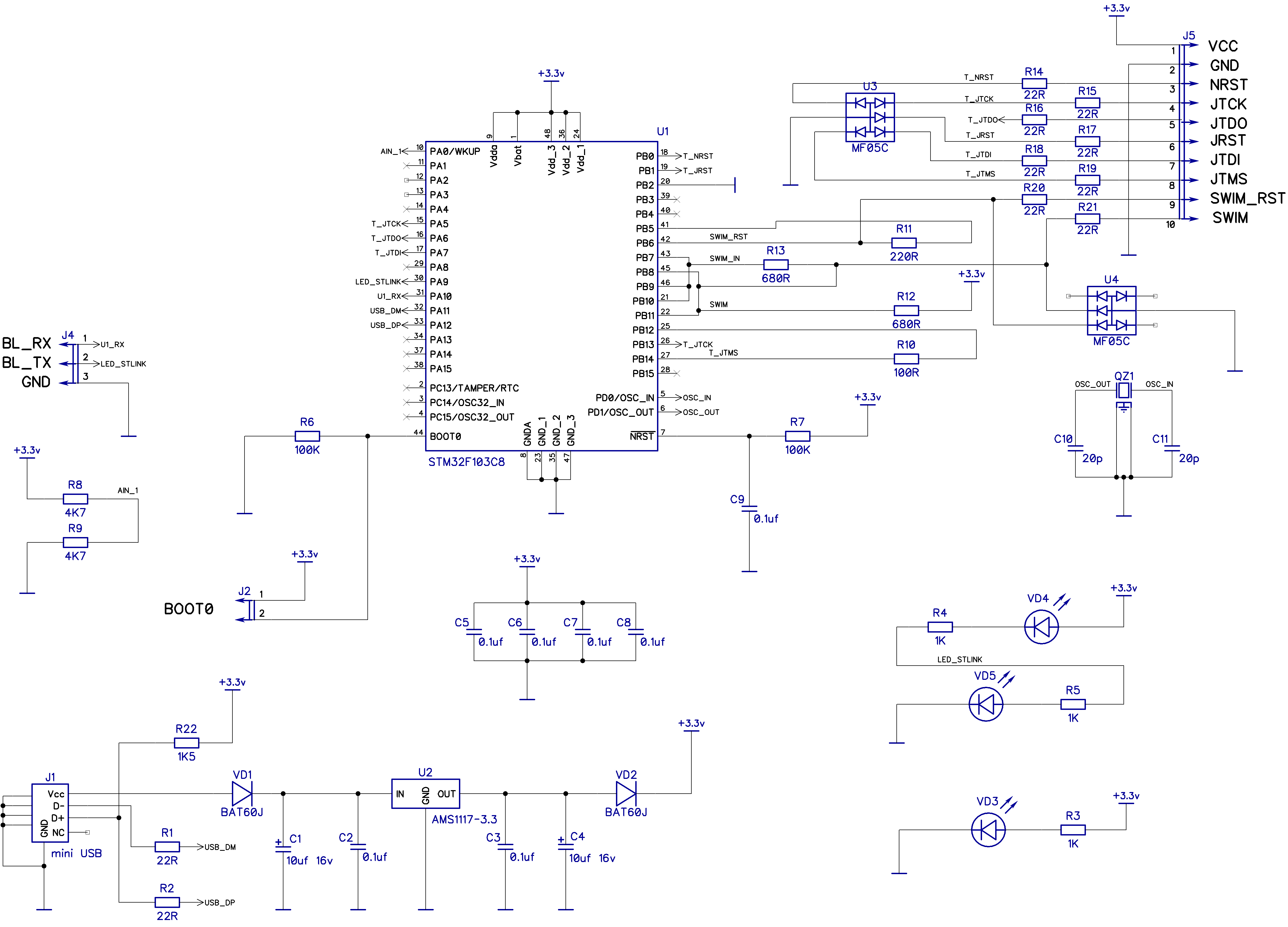