I just got a blue pill. And along with it I bought a St-link V2 to program it. After a long search I’ve figured out how to hook things up:
(3.3v)—(3.3v)
(T_SWCLK)–(DCLK)
(T_SWDIO)–(DIO)
(GND)—-(GND)
Please correct me if I’m wrong here.
Now my problem is…i want to upload a sketch with the Arduino IDE (still using 1.6.9). A simple Serial.println(“something”); would do…just to test it.
However when I plug in the ST-link (and the board connected to it), the port doesn’t seem to be recognised.
I’ve downloaded the drivers (i hope they’re the correct ones), so when I plug in the st-link my pc does recognize it.
I have no idea if I should select something differently in the settings or what ever else I’m doing wrong.
Btw, the bluepill does work, since i’ve uploaded sketches onto it through the TTL usb thingy before, but now I wanna use the ST-link.
Please heeeelp
You don’t need any port for STLink.
and the Upload method: STlink
Everything else I just left as is.
What should I select as the programmer? Also if I manage to upload a sketch, how can I see the output aka if I want it to print something onto the screen, how will i see it?
Can you post the Arduino message?
Device manager says it’s “STMicroelectronics STLink dongle”
If I try to upload a program, it seems to upload it properly, even without a port selected, however I have no idea if it’s actually on the board, since I want it to print to screen, but I can’t see the message, since no port is selected.
If I try to open the Serial monitor in Arduino IDE, it says Board at COM3 is not available.
use the usb connection to supply the main power and only connect SWCLK/SWDIO and GND lines.
if you add displays etc, they in turn should have their own supplies. Only the GND is common.
stephen
Also I’ve tried a blink sketch. I set PC13 as output and then do a digitalWrite, but the LED does nothing :S
However, LED should blink, when set to 0.
Is BOOT0 jumper on “0”?
Is BOOT0 jumper on “0”?
Also I’ve tried a blink sketch. I set PC13 as output and then do a digitalWrite, but the LED does nothing :S
BOOT0 must be set to 0.
And yes, you have to add the flag.
Restart IDE afterwards.
USB=>st-link=>stm32
I’ve also tried powering the stm32 from a powerbank over the usb port and unhooked the 3.3 power coming off of the st-link
I bought the stlink on aliexpress, so I’m guessing it’s a clone
Add the flag…could you please tell me what exactly I need to type and where? (arduino/hardware…then boards in arduino or continue to the stm foulder and change the boards there?)
Is BOOT0 jumper on “0”?
Is BOOT0 jumper on “0”?
Set boot0 to 0.
As Rick said, concentrate on led blink.
Is the power led on?
Post here the build and upload messages from IDE.
Set boot0 to 0.
As Rick said, concentrate on led blink.
Is the power led on?
Post here the build and upload messages from IDE.
void setup() {
pinMode(PC13, OUTPUT);
}
void loop() {
digitalWrite(PC13, HIGH);
delay(1000);
digitalWrite(PC13, LOW);
delay(1000);
}
Btw what should I select as the programmer? I have it set to AVRISP mkII
Programmer shouldnt make any difference.
unzipped it and pasted it into my arduino hardware folder. I haven’t changed any flahs…or should I have?
Do I need to comment or undomment something somehwere?
Try again after this setting.
Both jumpers should not be 0, The one near reset button set to 0 and the other one set to 1.
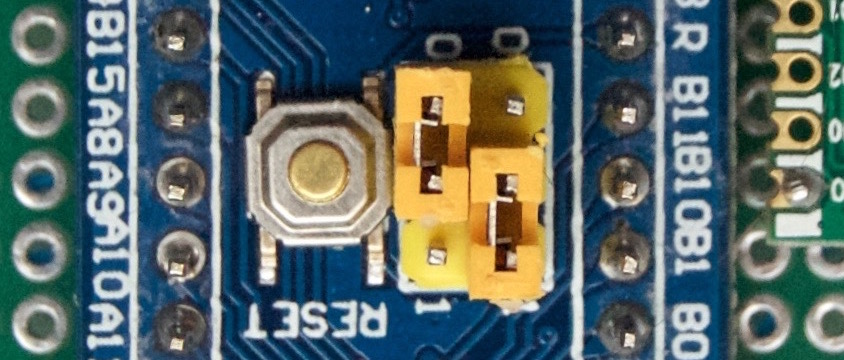
- STM32F103 with ST-LINK Jumpers Setting_1.jpg (115.98 KiB) Viewed 519 times

