5 pads are on the bottom allowing to flash the stm32f103c8t6 (gnd,5V,boot0,TX,RX). I flash one with a black magic probe firmware (need some hacks) and it is working.
Its certainly a nice way to get a STM32F103 as a dongle device, as I suspect you can use 7 of the pins as GPIO or possibly ACD etc.
And I suppose if you wanted to, you could also use the SWD and SWCLK pads on the back for additional GPIO
more than 2 per order ramps the postage in & up.
stephen
Special cable has free shopping to Italy, I got one too.
I believe that you have chosen a different shipping.
I have seen this before where you have to do multiple orders of 2 x, because if you exceed some number (perhaps because of the weight) you get charged a lot for postage
I’m not sure why you need a special cable, unless you like labels
Its far cheaper to buy this, and you get loads more spare for other things
Its far cheaper to buy this, and you get loads more spare for other things…
Well it is a question of personal preferences that it is better to spend: time or money.
And I don’t know that it is more important for a hobby, honestly.
I think I must be missing something here
I’m always wiring up SWD cables to STM32 and nRF51822 board, from JLink and BMP and STLink adaptors.
Unless the board has one of those big JLink cables, I just use 4 strands of the dupont cable, normally brown or black for GND, Red for Vcc, Yellow for SWDCLK and Orange for SWDIO
As my STLink, BMP and JLink programmers all have different pin arrangements, I just follow the same colour code each time and it all works fine.
But perhaps those cables do something else I don’t understand.
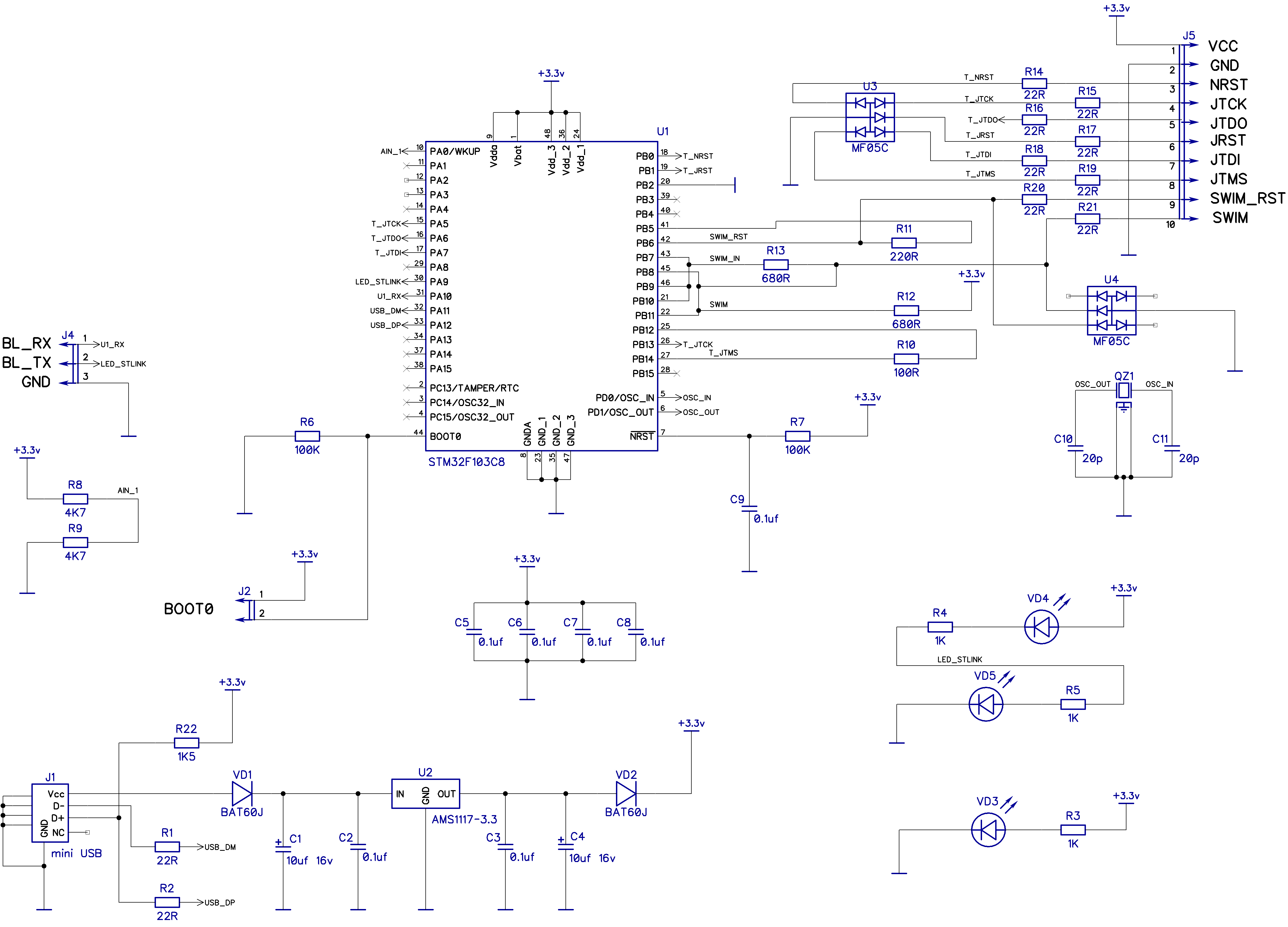
R13 is 220ohm
R14 to R21 are 220ohm.
PB1 is unconnected (no pin JRST).
NRST (schematics) is labeled T_JRST.
LED_STLINK is only connected to 1 led.
Maybe there are others differences.
https://www.aliexpress.com/item/20-14-1 … .57.rWctUq
tried for a back of the board screen shot 785k png
one day i’ll find my phone … … …
st-links, both of mine updated their s/w, one is 103c8t6, other 103cbt6, one has nrst & 3v3 brought out,
t’other 3v3 & 5v. 4 pin holes are present as well.
they’re the plastic shrink wrapped usb ones, but i have a scalpel aka stanley knife.
i know there’s a massive thread on re-programming them as well, i’ll go and refresh the braincell.
oh my 5yr+ kindle seems to have really died – tried it a couple of weeks back as well. cpr worked and i did a snapshot.
its had its encounters with gravity, but not too bad for a slide and release power switch ![]()
stephen
5 pads are on the bottom allowing to flash the stm32f103c8t6 (gnd,5V,boot0,TX,RX). I flash one with a black magic probe firmware (need some hacks) and it is working.
I presume you had to move PA4 and PA5 to some other pins.
Thanks for that.
I’m running a custom version of the BMP with fixes for nRF51, and support for GD32 and Maple mini as well as the STM32F103C8
So I’ll clone the official BMP repo (at the commit you referenced) and apply your diff’s then compare with my custom version, to the patched official version to see what needs to change.
I presume you just changed the UART and the pins for the SWD and LED (and also had to allow for the STLink connecting 2 pins in parallel for the SWD terminals (which the BMP doesn’t do ( at least not in my version))
Cheers
Roger
I’ve double checked the pins on this device and the pinout is as you listed except that some pins are connected together on the PCB via some low value resistors e.g. 220R or 680R (which is normal for a STLink dongle)
1.	T_JRST				PB0

2.	3V3

3.	5V

4.	T-JTCK/T_SWCLK		PA5 & PB13

5.	SWIM				PB7,PB8,PB9,PB10,PB11

6.	T_JTMS/T_SWDIO		PB12 & PB14

7.	GND

8.	T_JTDO				PA6

9.	SWIM_RST				PB5 & PB6

10.	T_JTDI				PA7
I couldn’t seem to get it to work using PB13 and pb14, so I used the same pins as you in the end.
The UART remapping works – Thankyou .
My version of the BMP doesn’t have any code that uses the reset pin, it must be a branch thats too old. So I’ll probably manually merge the more recent code when I get time and confirm it all still works OK.
But at least the version I now have works fine on my STM32F103C8 board
could you please explain which connections are used to flash the BAITE ST-LINK?
Thanks!
gnd,5V,boot0,TX,RX
@denis reflashed using usb to serial on the TX and RX pins by pulling boot0 high during power.
Note don’t use the 5V to pull boot0 high, use the 3.3V output from your usb to serial converter
I used the explanation from this site: http://embdev.net/articles/STM_Discover … agic_Probe to compile the source files.
After spending a lot of time to apply the patches from post “by denis » Tue Sep 27, 2016 11:42 pm” I flashed the BAITE ST-Link but it´s not working
Windows shows an unknown device. Hardware details are showing errors like DEVICE_DESCRIPTOR_FAILURE.
I used STMFlashLoader Demo.exe to flash the two bin files, first the blackmagic_dfu.bin to address 0x8000000 and then blackmagic.bin to address 0x8002000. Do you have any idea what´s wrong?
Edit: My file blackmagic.bin is about 70KB but the flash size is only 64KB ![]()
Why is the bin file size too big?
After starting gdb and connecting to COM port
monitor versionMy repo only works for nRF51
But please take a look at my questions at the bottom of my last post regarding BOOT jumper and how to get the version you used from git.
Thanks a lot!
If code is running which disables the SWD pins, then if you set boot0 and reset, the code will not be running and hence you can access the SWD pins
Its possible that your BluePill is read protected but it may be possible to do a full chip erase (the command is erase_mass I think or mass-erase)
I know that deprotects it on the nRF51 but it would may be different on the STM32 code in the BMP
gnd,5V,boot0,TX,RX
@denis reflashed using usb to serial on the TX and RX pins by pulling boot0 high during power.
Note don’t use the 5V to pull boot0 high, use the 3.3V output from your usb to serial converter
The 3.3v output from the USB to serial is ideal for pulling boot0 hight, but you need to remember to plug the baite stlink in, after the usb to serial is already plugged in and producing 3.3v for boot0 on the baite stlink
I have received mine but it uses an stm32f101c8t6 so I am a bit disappointed.
I had planned to flash it with BMP firmware. I have already a Blue Pill converted but a USB dongle is more convenient.
I have opened a dispute about that on Aliexpress but Baite answered that it is not written in the description what chip is used (that’s true) and the functionality id the same. ![]()
Maybe I will try to flash the BMP firmware anyway, with a proper set target.
Looks like Baite are cutting their costs. I have several Baite STlinks, some of which I converted to Blackmagic probes, and they were all F103’s
might be missing a couple of 103c8 jtags
the jtag ice is in exactly the same plastic casing
srp
martinayotte wrote:viewtopic.php?f=37&t=122&p=4422&hilit=stm32f101#p4422
viewtopic.php?f=35&t=1357&start=10#p18332
And it works nicely!
Thanks!
It is now time for me to Donate to the great BMP project
viewtopic.php?f=35&t=1357&start=10#p18332
And it works nicely!
Thanks!
It is now time for me to Donate to the great BMP project
Shame that Baite have decided to use the F101 instead of the F103, in some ways it would be better if they used the F103CB (128k), because the 128k STLink’s have UART as well as SWD, and they are also upgradable to be a JLink, using a publicaly available upgraded produced by Segger
Shame that Baite have decided to use the F101 instead of the F103, in some ways it would be better if they used the F103CB (128k), because the 128k STLink’s have UART as well as SWD, and they are also upgradable to be a JLink, using a publicaly available upgraded produced by Segger
They only used F103C8 (64k) in their F103 version and only the F103CB version (128k) supports the UART in the STLink software as I think the UART version of the STLInk is just a little to big to fit in 64k. This is because the STLink has its own bootloader system, but the bootloader is quite large (possibly 20k I can’t remember the precise details)
finished flashing a baite st-link clone into a BMP!
I am having a problem when trying to find connected targets!
bmp connected directly in a macbook usb port (target “bluepill” powered by the bmp)
any help is always welcomed ![]()
% arm-none-eabi-gdb blink_v0.elf

GNU gdb (GNU Tools for ARM Embedded Processors) 7.6.0.20140731-cvs

Copyright (C) 2013 Free Software Foundation, Inc.

License GPLv3+: GNU GPL version 3 or later <http://gnu.org/licenses/gpl.html>

This is free software: you are free to change and redistribute it.

There is NO WARRANTY, to the extent permitted by law.  Type "show copying"

and "show warranty" for details.

This GDB was configured as "--host=x86_64-apple-darwin10 --target=arm-none-eabi".

For bug reporting instructions, please see:

<http://www.gnu.org/software/gdb/bugs/>...

Reading symbols from /Users/mvcorrea/Private/vscode/ARMDEV_v0/projects/blink_v0/build/blink_v0.elf...done.

(gdb) target extended-remote /dev/cu.usbmodemE1C59EA1

Remote debugging using /dev/cu.usbmodemE1C59EA1

(gdb) monitor version

Black Magic Probe

Copyright (C) 2015  Black Sphere Technologies Ltd.

License GPLv3+: GNU GPL version 3 or later <http://gnu.org/licenses/gpl.html>
(gdb) mon tpwr enable
(gdb) monitor jtag_scan
Target voltage: 2.4V
JTAG device scan failed!
(gdb) monitor swdp_scan
Target voltage: 2.2V
SW-DP scan failed!
(gdb)
Target voltage: 2.3V
SW-DP scan failed!
(gdb)
My older variants only have the pads on the bottom which connect to PA9 and PA10 to reflash via Serial
So I think the core part of STM version, would need to be updated to have a tx dev and rx device
It think it depends on the wiring of the dongle(s) which seems to vary
I’m trying to find a definitive schematic for one of the STLink’s in the rectangular metal tube.

It could be that RST is SWIM_RST, in which case its not a problem because UART can be on PB6 and PB7, but if RST means T_NRST that appears to be on another pin
The other problem seems to be the pullup and series resistors, as it prevents serial loopback working.
so that’s at least 2 types, so 4 if they’ve done the same using 101’s
stephen
OK.
I tried a Baite STLink and loopback didnt work, but it would communicate to another USB to Serial adaptor
I’m probably going to find and remove the pullup (which could be as low as 680 ohms !)
My Baite STLink has a F103 in it, but from what people have posted recently they now contain F101’s
I bought several Baite versions when they came out, because they had the F103 in them, and they fully run the normal bootloader and code etc.
And there are a few more pins broken out to the back connector, as I thought they may come in handy for some projects where I needed a Dongle form of board
But so far I’ve not found a use for them apart from STLinks and BMP’s
[vargham – Wed Jun 28, 2017 3:35 pm] –
I ordered two at the same time from the same store. One has 101 and the other has 103.
LOL…
BTW. They still did not respond to my contact request on their Aliexpress store apart from saying the would pass the information on to an engineer.
I just can’t comprehend how these companies operate. Perhaps it’s just a one man operation.
istr usb-stlink sticks needs some wires tacking on, but any tacking required would a lot easier on the pill
stephen
[aster – Sat Jul 08, 2017 10:04 am] –
Would be possible to use a stlink with f101 as bmp? Or it is better to use a black/blue pill?
Depends if just want SWD or want Serial as well.
Only some have the connections for both.
[zmemw16 – Sat Jul 08, 2017 11:12 am] –
pretty sure this has been asked/mentioned somewhere above ?
istr usb-stlink sticks needs some wires tacking on, but any tacking required would a lot easier on the pill
stephen
It has been discussed for the f103 based st link. No one ever asked for the f101 if i m not wrong
[RogerClark – Sat Jul 08, 2017 12:43 pm] –
Depends if just want SWD or want Serial as well.Only some have the connections for both.
Both would give a better debugging experience ![]()
I forgot to send the pictures of my stlink f101


[vargham – Mon Mar 19, 2018 4:06 am] –
Clones with F101 die randomly and regularly. Some of them works for years, some of them dies after a few occasions: “Device Descriptor Request Failed” So it’s worth taking the more expensive with F103. Or build one from a bluepill. Two LEDs and a few resistors.
Its almost impossible to know which STLink’s use the F103 and which use the F103
The original Baite branded STLink’s I bought over a year ago were F103’s but the newer ones seemed to be F101’s ![]()


