The code in the official repo from Bill Greyman has now the support for the libmaple based core (stm32duino) integrated in it. So no need to download it from my repo any more.
Official SD-Fat library repository:
https://github.com/greiman/SdFat
===============================================================
UPDATE TO THIS WARNING. SHOULD BE SOLVED IN THE LATEST REPO. If you have problems using pin 7 for CS, make sure you are in sync with Roger’s master STM32Duino repo.
WARNING!!
I was just testing an SD card with one of the sketches, and noticed that you CAN NOT use pin 7 in the maple mini (the stm32f103 native SS pin for spi1) for CS. I have not looked at how the library manages CS and how that pin is setup in out SPI library, but I guess there is a conflict in the pin mode. So the work around at the moment is to use a different pin for CS.
– Updated 06/04/2015-
– New update on 07/10/2015 – Small code changes to the library and specially to the SPI library, which should go to Roger’s master repo soon.
So as I posted before in the forum, I modified the latest SdFat library from Greiman.
I had submitted him changes for a previous version, but had issues. Now all the issues seem to be corrected in my latest version.
It is available here:
https://github.com/victorpv/SdFat
It seems to work fine for me for the few examples I have tested.
If you want the best performance for large transfers, can use DMA mode.
DMA would be advantageous for large transfers, but doesn’t help at all, and may even have a penalty, if you are just reading a few bytes to a log and things like that. Now if you transfer images or mp3 files from the sdcard, DMA can improve performance greatly, anything involving big blocks at once.
DMA can be enabled or disabled editing SdSpiSTM32F1.cpp, there is one #define line:
/** Use STM32 DMAC if nonzero */
#define USE_STM32F1_DMAC 1
Comment that line or change the 1 for 0, and DMA transfers will not be used.
RECOMMENDATIONS FOR SPEED:
Use DMA mode.
Set a bigger buffer, ideally 4KB
Read speeds without DMA, 4KB buffer:
read speed and latency
speed,max,min,avg

KB/Sec,usec,usec,usec

676.29,8189,5927,6056

676.38,7467,5927,6054

676.38,7468,5927,6054

676.38,7469,5926,6054

676.38,7472,5926,6054
does it matter, if you post some examples written by you? It would be easier for us…
thanks!
I ported it mostly just to test the sdcard connector in the back of my display, in case I needed it in the future.
From the examples included in the library I have tested:
ReadWriteSdfat
Bench
Sdinfo
Printbenchmark
The only thing I may use it for, will be to hold small images for the display, but have not tested it for that yet.
I updated the SPI library (with DMA off) to the one you posted and the new SdFat library you posted cannot detect my card?
Says SD card initialisation failed with the quick start example, even though I’ve tried different CS pin values.
However, It works fine with the SD card library bundled with the Arduino IDE, I can see the text file written to the card, any ideas?
Using STM32F103 RET6
Thanks,
Sky
in the quick start example the SPI speed is set on this line:
const uint8_t spiSpeed = SPI_HALF_SPEED;
Change that to:
const uint8_t spiSpeed = SPI_CLOCK_DIV4;
Make sure you set the SPI to DIV2 to DIV8, they work pretty good for most sdcards.
Some slower cards may have problems with the fastest speed, but DIV4 pr DIV8 should for for most.
Let me know if you still have problems.
I have failed for SPI.h was missing.
I haved included SPI, and then I get the following compile error :
In file included from sketch_may08a.ino:11:0:
C:\Users\Jean-Marc\Documents\Arduino\libraries\SdFat/SdVolume.h:25:2: error: #error SdVolume is deperacated. Remove this line to continue using this class.
#error SdVolume is deperacated. Remove this line to continue using this class.
What should I do?
I gave it another try and there is no chance to get it working, equal which settings I use (different SS pin (1,9,8, NOT 7..), different spi speeds, dma on/off…..) I always got in the quicktest example
SD initialization failed.

Do not reformat the card!

Is the card correctly inserted?

Is chipSelect set to the correct value?

Does another SPI device need to be disabled?

Is there a wiring/soldering problem?
errorCode: 0x1, errorData: 0x0
Last time i downloaded it, about 2 weeks ago, SDFat would not even compile.
i think Victor send a Pull Request to the author, which only worked with the modified code that victor has on his machine.
I tried downloading Victors version from GitHub, but that did not work either ;-(
So I am currently using the old lib. The old lib seems mainly ok, but i do occasionally get a glitch when trying to play MP3 files from SD to VS1053.
But i have not had time to find the cause, because sometimes it can run for many hours without a problem
i will clone your repo again and see if it works.
it could just have been that PA4 SS issue, but i cant really remember as it was some time ago (but i thought one of my test rigs used PB5 for SS)
Working:
The old LC-soft adapter (big one) is working http://img.dxcdn.com/productimages/sku_142121_1.jpg
Not working (but with the SD-library)
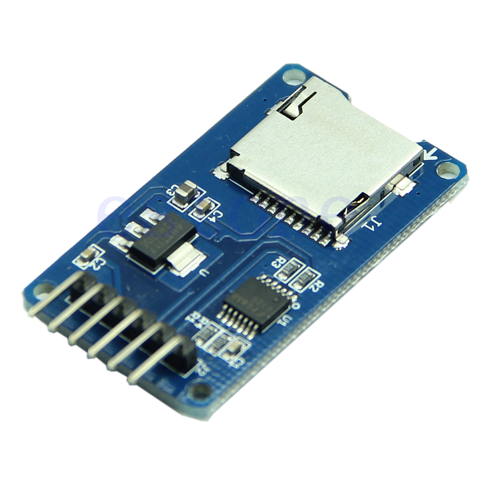
The micro one for the UNO (with the 5V multi-converter chip) http://img.alibaba.com/img/pb/659/697/9 … 59_679.jpg
SD cards tested: Transcend 4GB microSD: not working, 2GB micro SD (no brand) working. Maybe a formatting problem?
Edit with the successful combination (LC soft adapter + 2GB) the quickstart example works even with SPI_CLOCK_DIV2 and DMA enabled.
Bench speed is like a turtle: 88kb/s even with DMA enabled (more things to try out….)
Which repo are you using for SDFat ? Victors one ?
That’s the adaptor I’m using too, but with the old SD. (I’ve didn’t retried SdFat from Victor since when I tried it on Netduino2Plus, it wasn’t working at that time few weeks ago)
On MapleMini, the LC-soft works well with plain SPI, but I’ve struggled to make it run with SPI(2). I wish SPI.SelectDev() will become handy soon … ![]()
Yes, the direct one from Victor’s github account.
I’ll try it again this weekend
/home//Arduino/libraries/SdFat/SdSpiSTM32F1.cpp: In member function 'uint8_t SdSpi::receive(uint8_t*, size_t)':

/home//Arduino/libraries/SdFat/SdSpiSTM32F1.cpp:172:7: error: 'class SPIClass' has no member named 'dmaTransfer'

SPI.dmaTransfer(0, const_cast<uint8*>(buf), n);

^

/home//Arduino/libraries/SdFat/SdSpiSTM32F1.cpp: In member function 'void SdSpi::send(const uint8_t*, size_t)':

/home//Arduino/libraries/SdFat/SdSpiSTM32F1.cpp:208:7: error: 'class SPIClass' has no member named 'dmaSend'

SPI.dmaSend(const_cast<uint8*>(buf), n);

^
see SPI.h —-> https://github.com/rogerclarkmelbourne/ … maTransfer
At least you must update the SPI library, but it’s better to update everything, because many innovations are linked together.
The whole dma stuff (like ‘dmaTransfer’) is for a some weeks within the SPI.h/.cpp itself and not in the individual libraries.
I have test using sdcard module without using leevel converter, and it work fine.
but it not work when using sd card module that have level converter.
I have test using sdcard module without using leevel converter, and it work fine.
but it not work when using sd card module that have level converter.
I have test using sdcard module without using leevel converter, and it work fine.
but it not work when using sd card module that have level converter.
I haven’t been using an extra capacitor for SDCards, but it makes much sense, I’ll start using it from now on anytime I see any problem.
EDIT: Just to add that personally I have used the SDCard slot in the back of an ili9341 board, which seems to work “mostly” fine, and also the adapter Madias linked before: http://img.dxcdn.com/productimages/sku_142121_1.jpg
That one works great all the time so far.
I also used the screen+touch at the same time, but never a combination of the 3 of them.
I was try to using CS pin in different pin.
using pin 8 and 9 is not working but when i use pin 1 and oin 2 is working
Using example Sketch.
Micro SD Sandisk 2GB, some test using DMA:
write speed and latency

speed,max,min,avg

KB/Sec,usec,usec,usec

1052.47,106079,2898,3888

1071.19,19437,2900,3820

1073.50,22139,2901,3813

1068.67,33005,2902,3829

1067.76,34606,2901,3833

1063.90,36557,2902,3845

1070.51,38904,2901,3823

1070.28,42891,2899,3824

1065.94,59471,2900,3838

1061.64,44357,2900,3855
Starting read test, please wait.
read speed and latency
speed,max,min,avg
KB/Sec,usec,usec,usec
1562.09,4049,2607,2621
1563.07,3180,2606,2619
1562.58,3183,2606,2620
1562.58,3183,2605,2619
1562.58,3183,2607,2619
I was try to using CS pin in different pin.
using pin 8 and 9 is not working but when i use pin 1 and oin 2 is working
sd.begin(SD_ChipSelectPin);
But if I add the parameter for the speed, it works fine:
sd.begin(SD_ChipSelectPin, SPI_CLOCK_DIV2)
Maybe the card, may be the default speed, I don’t have time to check it out right now, just wanted to post it in case it helps someone.
I’m getting an error during compiling any of the exemples
‘SPI_DMAC_TX_CH’ was not declared in this scope
I’m working with a bluepill STM32F103C8T6 board.
I tried with both the stable branch on the github and the beta repository.
I had a quick look at the SdSpiSTM31F1.cpp and i’ve found definition for SPI1_DMAC_TX_CH but not for SPI_DMAC_TX_CH
#define SPI1_DMAC_RX_CH DMA_CH2
/** DMAC transmit channel */
#define SPI1_DMAC_TX_CH DMA_CH3
Is it possible to fix it ?
Regards,
\%user%\Documents\Arduino\libraries\SdFat\src\SdSpiCard\SdSpiSTM32F1.cpp: In function 'void SPI_DMA_TX_Event()':

\%user%\Documents\Arduino\libraries\SdFat\src\SdSpiCard\SdSpiSTM32F1.cpp:40:21: error: 'SPI_DMAC_TX_CH' was not declared in this scope

dma_disable(DMA1, SPI_DMAC_TX_CH);

^

\%user%\Documents\Arduino\libraries\SdFat\src\SdSpiCard\SdSpiSTM32F1.cpp: In member function 'uint8_t SdSpi::receive(uint8_t*, size_t)':

\%user%\Documents\Arduino\libraries\SdFat\src\SdSpiCard\SdSpiSTM32F1.cpp:148:28: error: 'SPI_DMAC_RX_CH' was not declared in this scope

dmac_channel_disable(SPI_DMAC_RX_CH);

^

\%user%\Documents\Arduino\libraries\SdFat\src\SdSpiCard\SdSpiSTM32F1.cpp:149:28: error: 'SPI_DMAC_TX_CH' was not declared in this scope

dmac_channel_disable(SPI_DMAC_TX_CH);
https://github.com/greiman/SdFat
Regards,
https://github.com/greiman/SdFat
Regards,
I’m now having issues to get the SDreader module working. Even I connect it alone for now on any of the 3 SPIs, SdFat won’t find it. My ILI9341 board comes with a 5 pins connector for the SDcard (F_CS, SD_SCK, SD_MISO, SD_MOSI, SD_CS). If I’m not mistaken, F_CS should be left unconnected as I don’t have the U3 SPI flash populated. I tried with a microSD module made for 5V VCC (just bypassing the 3.3 voltage regulator) and it works. Well I’ll put it on hold for now as i have other issues to address first with the bootloader.
Best regards,
I have an Olimexino board with an SD card attached and I find that the SD libraries assume that there is only one SPI peripheral when in fact we have two (on the olimexino, it’s on SPI2 that the SD card is connected).
Do you think this could be changed in the library?
SD_SPI_CONFIGURATION is the define that let you choose if you rely on Hardware or Software SPI, or even a custom one.
In my case, for Netduino2Plus, a F405, the SDCard is hooked up on SPI3 and is working marvellously.
Although, it is a bit clunky having to dig through the library files to find which SPI was configured. Since the CS pin is possible to configure, it would make sense to be able to configure which SPI peripheral to use. But… that’s just my opinion.
Although, it is a bit clunky having to dig through the library files to find which SPI was configured. Since the CS pin is possible to configure, it would make sense to be able to configure which SPI peripheral to use. But… that’s just my opinion.
In my case, I need to change to SPI2 as my board has the SD card wired into SPI2 (nothing I can do about it)… considering that another user has it on SPI3, it’s already two people that had to change the library because it’s not “possible” to use SPI1.
I remember testing an SdFat library about two years ago and we passed an SPI object for it to run the SD functions on. It was just a little bit more transparent, I guess.
Still, thanks. I’ve tested one of the examples and it recognized the card.
If I wanted to log AD values into the SD, what would be my maximum achievable frequency? Any numbers off the top of your heads?
It does NOT though allow for a real time device like an always-on telemetry radio using SPI – because it needs to have the RX on all the time and that can create an interrupt at any time, and the ISR uses the SPI.
For SD cards, etc, SPI transactions is fine
I didn’t have any success yet with the SD module of my ILI9341 LCD display, and the optimized SdFat library.
To be sure It’s not an hardware issue with my ILI9341, I’ve tried with a Teensy 3.1.
Paul PaulStoffregen spent some time doing similar improvements to the teensy 3.xx Sd library.
I can get read/write working only when I disable the optimization flag in the library configuration file (optimization flag doesn’t work with any of my microSD (512MB, 2GB class 4, 8GB class 4, 16GB class 12), or should it be because the module doesn’t have the SPI RAM populated on the board.
Here is a link on our talk on the PJRC forum :
https://forum.pjrc.com/threads/29331-TF … #post81454
Now with my STM32F103C8T6 (bluepill)
I tried EVERY digital pins for the SD_CS line.
I’ve disabled the DMA optimization for initial tests in the config file SdSpiSTM32F1.cpp
#define USE_STM32F1_DMAC 0
I’ve tried to use SPI1 for both the ILI9341 display and SD module, with a dedicated CS pin for the SD_CS.
I’ve tried the latest SPI library with the new SPI.setModule(2); in the setup section of my code. In that case I hooked the SD miso/mosi/sck on the SPI2, and specified the SD_CS (I tried the SS of the SPI2 and other pins like 0, 1 because I’ve seen some users got success with a mapple mini with that configuration)
Last but not least, I’ve tried various DIV_CLOCK settings (2, 4, 8) with no success too.
const uint8_t spiSpeed = SPI_CLOCK_DIV8;
If I define a pin with the STM32F103C8 naming scheme (PAxx/PBxx/PCxx, etc…), the display works, but, if i compile the sdinfo test sketch, I have a different numbering on the serial monitoring. For exemple, my PB13 has the pin number 33 shown on the serial monitor.
I don’t know what else to do now…
here is the code i use:
#include <SPI.h>

#include <SdFat.h>

#include <SdFatUtil.h>

#include <ILI_SdSpi.h>

#include <ILI_SdFatConfig.h>

#include <ILI9341_due_gText.h>

#include <ILI9341_due.h>
// CS and DC for the LCD
#define LCD_DC PA1
#define LCD_CS PA4
#define LCD_RST PA0
#define SD_CS PB12 // Chip Select for SD card
#define BUFFPIXELCOUNT 320 // size of the buffer in pixels
#define SD_SPI_SPEED SPI_HALF_SPEED // SD card SPI speed, try SPI_FULL_SPEED
const uint8_t spiSpeed = SPI_CLOCK_DIV8;
SdFat sd; // set filesystem
SdFile bmpFile; // set filesystem
//ArduinoOutStream cout(Serial);
ILI9341_due tft(LCD_CS, LCD_DC, LCD_RST);
// store error strings in flash to save RAM
#define error(s) sd.errorHalt_P(PSTR(s))
void setup()
{
Serial.begin(9600);
SPI.setModule(2);
tft.begin();
tft.setRotation(iliRotation270); // landscape
progmemPrint(PSTR("Initializing SD card..."));
if (!sd.begin(SD_CS, SD_SPI_SPEED)){
progmemPrintln(PSTR("failed!"));
return;
}
progmemPrintln(PSTR("OK!"));
}
I have a problem with my SD card connected to a Maple mini clone.
I run the SdInfo sketch combined with the RawWrite sketch and it seems that no data can be written to the SD card.
Installed the latest versions from victorpv/SdFat and from the rogerclarkmelbourne/Arduino_STM32 github.
I am using SPI 2 with SPI_CLOCK_DIV8.
Reading from the SD card works. The card was formatted with SdFormatter.
A serial log looks like this:
SdFat version: 20150321
Assuming the SD is the only SPI device.

Edit DISABLE_CHIP_SELECT to disable another device.
Assuming the SD chip select pin is: 31

Edit SD_CHIP_SELECT to change the SD chip select pin.
type any character to start
init time: 1 ms
Card type: SD2
Manufacturer ID: 2

OEM ID: TM

Product: SA02G

Version: 0.3

Serial number: A07C6B9C

Manufacturing date: 12/2008
cardSize: 1973.42 MB (MB = 1,000,000 bytes)

flashEraseSize: 128 blocks

eraseSingleBlock: true

OCR: 80FF8000
SD Partition Table

part,boot,type,start,length

1,0,6,135,3854201

2,0,0,0,0

3,0,0,0,0

4,0,0,0,0
Volume is FAT16

blocksPerCluster: 64

clusterCount: 60214

freeClusters: 60212

freeSpace: 1973.03 MB (MB = 1,000,000 bytes)

fatStartBlock: 136

fatCount: 2

blocksPerFat: 236

rootDirStart: 608

dataStartBlock: 640
Starting RawWrite...

removing RAW.TXT...

creating contiguous...

createContiguous failed

SD errorCode: 13

SD errorData: FF
Did you try on SPI1
SPI.setModule() is a fairly new feature, and I can’t recall if anyone fully tested it with SD cards
In both cases I get cardBegin error 0x02 0xFF.
What am I doing wrong?
But I have some news.
I tried to visualize the SPI CLK signal on my oscilloscope and – voila – it started to work on SPI 1!
But not on SPI 2.
It seems that the impedance on the SCK line is critical.
Can any of you acknowledge this?
You don’t need to call setModule(1) for SPI 1, its only required if you need to move the SPI class to use SPI2 or on some boards SPI3
Re: SCLK
I’ve not tried this on the Maple mini
I did build a simple audio player that read wav’s from a SD card on SPI1 and played them out a SPI audio interface on SPI2 and that worked reasonably well, but I did get occasional gitches on reading the SD card.
But the original SD card lib that the Arduino uses was not that good, and I recall that there has been some work done recently to improve it.
I think @victorPV may be the person who knows the most about this, as he wrote the DMA support for SPI and had it working with SD cards at one point.
For SPI 1, it’s true, setModule(1) has no influence.
I’ll post later some results.
I have a problem with my SD card connected to a Maple mini clone.
I run the SdInfo sketch combined with the RawWrite sketch and it seems that no data can be written to the SD card.
Installed the latest versions from victorpv/SdFat and from the rogerclarkmelbourne/Arduino_STM32 github.
I am using SPI 2 with SPI_CLOCK_DIV8.
Reading from the SD card works. The card was formatted with SdFormatter.
A serial log looks like this:
SdFat version: 20150321
Assuming the SD is the only SPI device.

Edit DISABLE_CHIP_SELECT to disable another device.
Assuming the SD chip select pin is: 31

Edit SD_CHIP_SELECT to change the SD chip select pin.
type any character to start
init time: 1 ms
Card type: SD2
Manufacturer ID: 2

OEM ID: TM

Product: SA02G

Version: 0.3

Serial number: A07C6B9C

Manufacturing date: 12/2008
cardSize: 1973.42 MB (MB = 1,000,000 bytes)

flashEraseSize: 128 blocks

eraseSingleBlock: true

OCR: 80FF8000
SD Partition Table

part,boot,type,start,length

1,0,6,135,3854201

2,0,0,0,0

3,0,0,0,0

4,0,0,0,0
Volume is FAT16

blocksPerCluster: 64

clusterCount: 60214

freeClusters: 60212

freeSpace: 1973.03 MB (MB = 1,000,000 bytes)

fatStartBlock: 136

fatCount: 2

blocksPerFat: 236

rootDirStart: 608

dataStartBlock: 640
Starting RawWrite...

removing RAW.TXT...

creating contiguous...

createContiguous failed

SD errorCode: 13

SD errorData: FF
On the Maple mini, I think you can get the incoming 5V from the USB input via the VIN pin. But I can’t remember if its via a diode from USB power, and when I tested on one of my Maple minis it showed 4.8V
Just check whatever you feed your SD card module with, that it does seem to give 3.3V to the SD card, as I’ve noticed that some USB outputs are as low as 4.75V and sometimes the regulators won’t work unless you supply around 5V
The SD card module has no regulator, and gets the 3.3V from the mini board. So no level converters are involved.
The card has class 10.
But I find strange that in order to work, the SCK line (SPI 1) had to be connected to the scope probe.
What does it actually mean? Wrong impedance?
Are the wires from Maple mini board to SD card module too long? Or too short?
Of course, the shorter the better, one would say. But the same length had no effect on Pro Mini with 8MHz SPI clock, fed from 3.3V supplied by a USB-serial converter board.
Maple mini SPI clock is 12 MHz according to the scope (DIV4). Is this 4MHz more than Pro Mini making so huge issues? Or is rather the shape of the signal?
Or is CPOL and/or CPHA issue? Or maybe NSS pin management related?
This is the direction I want to make more scope recordings, I think this would give answer to some users here in forum.
What do you think?
Does it make sense?
Meanwhile I will try to put an extra 10uF filtering capacitor to the 3.3V line and check whether it makes a difference or not.
Oh yes, I would like to finally have the SD card working on SPI 2 since I need the analog input pins 0…9 for my project.
I rather think that the probe actually introduces flatness (filtering instead of inducing noise) and/or phase shift to the signal.
The SCK signal on the scope display was quite ok, no spikes, sinusoidal shape.
I will post some more results later.
stephen
Its always amazed me that running clocks and data at 10s of megahertz , down bits or normal wire or ribbon cable, works at all ![]()
These sorts of frequencies would have been considered “High Frequency” RF about 30 years ago.
To get sharp edges on square waves actually requires bandwidths of many hundred of Mhz.
Anyway.. I have experienced issues with crosstalk on ribbon cables on SPI, in the past,
So i suspect you are experiencing something similar, or ringing of the SPI clock or data lines.
The sketch is started, and the recording is triggered by the very first rising edge of the SPI 1 clock SCK.
Yellow is the SPI 1 SCK (pin 6), blue is CS chip select (pin 31 in my case, which belongs to CS of SPI 2).
A successful start – only the first millisecond – I suppose this is the introducing part with “sd.cardBegin()”:

red is the first zoom in:

yes, clock pulses are activated before an active chip select!
and yes, the first 4 (as well as following consecutive group of 3) rising edges are slow.
and here the second zoom in (green rectangular form the first image):

There are 2 kind of pulse trains: smaller (left side of the CS high period) and larger (right side of CS high period).
The smaller are (let’s call them) “high-frequency” pulses (27MHz), here the last train generated after CS goes “high” !!!

and the larger are low-frequency (9MHz) pulses:

I think, these are the right pulses, how they always should be. But they aren’t, specially not at the beginning, where 27MHz pulses are generated.
Then after some condition, the CS is generated correctly before SCK (second falling CS edge), and the SCK pulses are also ok, the frequency goes down to 9MHz, which was actually selected by the sketch with SPI_CLOCK_DIV8:

a better zoom in:

And, at the end, after second rising CS edge, again, there are some additional clock pulses generated:

Well, I don’t know what exactly is happening here, but it definitely strange.
Can someone explain these?
EDIT:
It looks like I managed to solve the probe issue, I soldered a 10uF capacitor directly onto the SD card module (Vcc-GND).
Now the sketch works on SPI 1 without the probe contact on SCK.
Probably the cross-talk has been decreased.
But the recorded signals still remained same as posted above.
TODO: record signals on SPI 2.
But what about the 27MHz frequency pulses on SCK? Are they also deliberately generated? For this I cannot find any meaningful explanation.
For me it looks like the SW tries to access the SPI bus before the correct frequency was set up.
And how about the funny behavior of the SCK before the 27MHz pulses come? The signal goes to “0” and after a while slowly back to “1”, seems like push-pull is not activated. What is the reasoning behind?
I have to take a deeper look into the SPI driver part used by the SdFat lib.
If you are using the one on the Maple Mini, labelled as SS, (I think its Pin 7) try using another one.
There is a known issue with the SS pin not behaving. Its a fault / feature of the STM32 its self, and there wasnt a lot we could do about it.
I recall we tried to put in a work-around for this pin missbehaving, but I can’t remember precisely what the issue was or what the work-around was.
I’m sure someone one the forum will remember the details ![]()
I’m sure someone one the forum will remember the details
Does this pin behave the same or have same bug as PA4?
Does this pin behave the same or have same bug as PA4?
1.- We found the part of the core in which the NSS pin is set to AF (to be controller by the SPI peripheral itself)
2.- We removed that line, so NSS remains as GPIO.
3.- From that point on the core allows to keep using the NSS pin as GPIO after an SPI port has been started. It is not under direct control of the SPI peripheral when you start the SPI port.
The above applies to any SPI port, 1 to 3 (in devices with 3 ports). So any code using controlling the CS pin as any normal GPIO pin can use the NSS pin for CS, or anything else for that matter. It is not NSS anymore in our core unless Roger reverted that change at some point, which I don’t remember reading.
EDIT:
Regarding the sck pulses when CS remains low, I am almost certain that is part of the normal way of communicating with the SD card. Do a search in google for SD card in spi mode, and you should find all the details, but I remember reading about a bunch of tricks that are done will all the control lines in the SD card to set them up. I just don’t remember the exact things that were done, but google is your friend ![]()
There it is all explained about those pulses:
http://elm-chan.org/docs/mmc/mmc_e.html
I have also found the place where the 74 or more SCK pulses (needed for SD card init) are generated while SS is high (inactive). However, these pulses are generated with a 27MHz clock (line 132 of SdSpiCard.cpp, using SPI_SCK_INIT_DIVISOR). Shouldn’t here already the input parameter “sckDivisor” be used? At least in the case where the SD card does not support 27MHz.
Another issue is the 3 slow and wide SCK pulses before the normal data transfer pulses. Did I understand correctly: this is a bug in the silicon and will be generated by the HW when the SPI CR register is written (e.g. data mode, bit order and clock divider)?
Can anyone confirm this?
A third topic (low prio) would be that it seems that spi_init() is superfluously called in line 133 of SdSpiCard.cpp. The init routine will be called anyway in chipSelectLow() (line 207), at the beginning of each card command. Btw, isn’t any faster option to set/clear the SS pin other than digitalWrite() – lines 296 and 279?
[Off topic: how can be generated a function call graph in the easiest way?Maybe automatically generated and checked in once after each code change?]
The problem with the SD card lib, is that from what I’ve seen, its code that has evolved over a number of years and I suspect there are lots of legacy calls which end up doing the same setup more than once.
In our SPI lib, it takes a cautious approach, so its quite possible that it re-inits more than it needs to, but this generally means that we don’t have that much trouble with it.
Re: faster methods than digitalWrite
Yes, plenty of faster ways.
There are internal gpio calls in libmaple that could be called directly
Or the hardware registers can be manipulated directly, and you could cache the CS port and mask details.
However on the whole, this isnt a big issue either, unless the code is setting and resetting CS every time a byte is transferred.
But really thats a issue with the higher level code, ie the library that is using SPI
Anyway, as I told, is not a big issue, and this place seems really not to be very critical since is one time action for transferring several bytes.
Still, the other issue with those 3 wide pulses on SCK line before the normal data transfer pulses really bothers me, they should not be there. And I am not sure whether they cause any problems when accessing the SD card, specially when they occur while SS is active low.
I think it is important to find out why are they there. I need to dig deeper…
I agree, we should not have extra pulses.
I think several people have looked at the SPI, with logic analysers and scopes, over the last 6 months or more, and I don’t remember anyone seeing any extra pulses, so this problem may be specific to the SD lib
Anyway. Thanks for investigating this strange phenomenon
I think it is important to find out why are they there. I need to dig deeper…

The SPI speed has not much influence on the run-time performance, DIV4 or DIV8 gives pretty much the same results, so I would suggest use DIV8 to keep on the safe side. DIV2 (full speed) haven´t tried yet.
The changes:
SdSpiCard:
– ::begin() – swapped call sequence between spiBegin() and spiInit(). I think it is normal that the initialization should be done before the interface is started (begin).
– chip_select_low() – remove the line with spiInit(), which has been already called in begin(), no need to call it all over again.
SPI.cpp
– remove the call of this.begin() from the functions setClockDivider(), setBitOrder() and SetDataMode(). Same reasoning, the SPI::begin already executed before.
After these changes the funny wide pulses are gone, no more pulses with 27MHz, the card behaves very robustly, no more scope probe problem at all!
The only small issue is a problem with the serial interface, some data sent with Serial.print() is sometimes not displayed, and other times is displayed doubled or tripled in the COM window. I am not sure whether my changes have influenced the DFU behavior or is just my PC which was not rebooted since a week…
Attached my local copy of these files.
The setup consists of only one SD card module on SPI 1, SS is maple mini pin 31, or PB12.
The same sketch as in my first post.
EDIT:
Here is the serial output:
SdFat version: 	******* the version number for some reason will not be displayed ******

init time: 0 ms
Card type: SD2
Manufacturer ID: 2
OEM ID: TM
Product: SA02G
Version: 0.3
Serial number: A07C6B9C
Manufacturing date: 12/2008
cardSize: 1973.42 MB (MB = 1,000,000 bytes)
flashEraseSize: 128 blocks
eraseSingleBlock: true
OCR: 80FF8000
SD Partition Table
part,boot,type,start,length
1,0,6,135,3854201
2,0,0,0,0
3,0,0,0,0
4,0,0,0,0
Volume is FAT16
blocksPerCluster: 64
clusterCount: 60214
freeClusters: 60207
freeSpace: 1972.86 MB (MB = 1,000,000 bytes)
fatStartBlock: 136
fatCount: 2
blocksPerFat: 236
rootDirStart: 608
dataStartBlock: 640
Starting RawWrite...
removing RAW.TXT...
creating contiguous file...
getting contiguous range...
Start raw write of 51200 bytes at
51200 bytes per second
Please wait 1 seconds
RawWrite done
Elapsed time: 1.00 seconds
Max write time: 557 micros
Overruns: 0
type any character to start
– remove the call of this.begin() from the functions setClockDivider(), setBitOrder() and SetDataMode().
I’m surprised this works.
if you look in setClockDivider, all it does is set a property called _currentSetting->clockDivider, it doesnt actually change the hardware
The reason it calls begin(), is because begin calls
spi_master_enable(_currentSetting->spi_d, (spi_baud_rate)_currentSetting->clockDivider, (spi_mode)_currentSetting->dataMode, flags);
Which actually sets up the hardware, and to do this it has to disable the SPI hardware and then make those changes and then re-enable the SPI hardware
It has to do this because some changes (I think bit order is one of them), can’t be changed if the SPI interface is active.
You could try writing a loop to call
    spi_peripheral_disable(dev);

spi_peripheral_enable(dev);
spiBegin() calls SPI.begin(), which calls spi_master_enable() after executing spi_init() and configure_gpios().
So I think the HW will be correctly initialised and started… that’s why is working… I guess…
I expect the default SPI config for some things like byte order, is fine for the SD card, which is why its working.
But if you remove the calls to begin() from the setByteOrder etc, some other devices will not work.
Can you test if its the act of disabling and re-enbling the SPI hardware that’s causing the glitch
It could also be that the code is returning the SPI pins to GPIO mode (probably inputs), which cause the glitches
I see what you mean, I also had some thoughts about it.
I checked the whole STM32 repo, there are quite few places (only 7 files!) where these functions are called.
In those cases the SPI.begin() is always called before.
I think this is generally not quite ok. In my view, begin() is not init(), and init() should come first.
I assume, the setByteOrder() and similar functions belong to init part, right?
That means, the working parameters should be setup first, and only afterwards call begin().
On the other side, the function SPI.begin() also calls the function spi_init(), which executes an RCC enable and reset. Hence, each time begin() is called, beside calling spi_master_enable(), the RCC is reset. I think the repeated RCC reset and master enable makes no sense and therefore should be avoided. Maybe this is the reason why what I got rid of glitches by applying my changes.
I know, one try to avoid changes which could affect other libs. But I think with these changes we could really improve the lib.
As an alternative to remove lines which call begin(), I would maybe introduce a semaphore variable to monitor whether begin() was called before, and don’t call it again if it is the case.
What is your opinion?
EDIT:
The reason it calls begin(), is because begin calls
spi_master_enable(_currentSetting->spi_d, (spi_baud_rate)_currentSetting->clockDivider, (spi_mode)_currentSetting->dataMode, flags);
Which actually sets up the hardware, and to do this it has to disable the SPI hardware and then make those changes and then re-enable the SPI hardware
Because of this, without changing the calling order of init() and begin(), the idea with semaphore variable won’t work.
The code for the SPI lib was inherited from the original Leaflabs libmaple libraries. We made some changes to it, but I don’t recall changing begin();
I don’t know why Leaflabs needed to call rcc_clk_enable or rcc_reset_dev, (unfortunately they have not responded to questions on github etc for well over a year, and they have not participated on the old leaflabs forum for several years (as far as I can tell).)
But I’d guess that you have to setup the rcc_clk and reset the SPI device before you can use it at all.
If some libs call begin multiple times, we could probably put flags into spi_init() so that it doesnt re-init if its already been inited, but I suspect that the reason that the is done on every call to begin() is in case someone decides to set the pinMode of on of the SPI pins, between calling one begin() on one transfer and another begin() on another transfer
Re: setBitOrder being called ??
I’m not sure what you mean. As far as I can see setBitOrder is only called in SPI.cpp from beginTransaction
If another lib or a sketch calls this, its out of our control
setBitOrder can be called at any time, before or after SPI.begin(), so I can’t see how the code can do anything but disable the spi hardware, change the setting, and re-enable the hardware
Albeit, it does this by calling spi.begin() but even if I copied the code from spi.begin() into setBitOrder, it would be the same code.
We can probably make some improvement by changing
void SPIClass::setBitOrder(BitOrder bitOrder)

{

#ifdef SPI_DEBUG

Serial.print("Bit order set to "); Serial.println(bitOrder);

#endif

_currentSetting->bitOrder = bitOrder;

this->begin();

}
If another lib or a sketch calls this, its out of our control
you can check it here: https://github.com/rogerclarkmelbourne/ … etBitOrder
Usually setBitOrder, setClockDivider and setDatMode are called sequentially after each other.
For example: https://github.com/rogerclarkmelbourne/ … _ports.ino.
void setup() {
// Setup SPI 1

SPI.begin(); //Initialize the SPI_1 port.

SPI.setBitOrder(MSBFIRST); // Set the SPI_1 bit order

SPI.setDataMode(SPI_MODE0); //Set the  SPI_2 data mode 0

SPI.setClockDivider(SPI_CLOCK_DIV16);      // Slow speed (72 / 16 = 4.5 MHz SPI_1 speed)

pinMode(SPI1_NSS_PIN, OUTPUT);
// Setup SPI 2

SPI_2.begin(); //Initialize the SPI_2 port.

SPI_2.setBitOrder(MSBFIRST); // Set the SPI_2 bit order

SPI_2.setDataMode(SPI_MODE0); //Set the  SPI_2 data mode 0

SPI_2.setClockDivider(SPI_CLOCK_DIV16);  // Use a different speed to SPI 1

pinMode(SPI2_NSS_PIN, OUTPUT);
}
One needs to recognize, also, that the Leaflabs core was written prior to Arduino 1.0 which was a huge architectural and structural change for Arduino libraries.
Ray
SPI.cpp
original function :
void SPIClass::beginTransaction(uint8_t pin, SPISettings settings)

{

#ifdef SPI_DEBUG

Serial.println("SPIClass::beginTransaction");

#endif

//_SSPin=pin;

//pinMode(_SSPin,OUTPUT);

//digitalWrite(_SSPin,LOW);

setBitOrder(settings.bitOrder);

setDataMode(settings.dataMode);

setClockDivider(determine_baud_rate(spi_d, settings.clock));

begin();

#if 0

// code from SAM core

uint8_t mode = interruptMode;

if (mode > 0) {

if (mode < 16) {

if (mode & 1) PIOA->PIO_IDR = interruptMask[0];

if (mode & 2) PIOB->PIO_IDR = interruptMask[1];

if (mode & 4) PIOC->PIO_IDR = interruptMask[2];

if (mode & 8) PIOD->PIO_IDR = interruptMask[3];

} else {

interruptSave = interruptsStatus();

noInterrupts();

}

}

uint32_t ch = BOARD_PIN_TO_SPI_CHANNEL(pin);

bitOrder[ch] = settings.border;

SPI_ConfigureNPCS(spi, ch, settings.config);

//setBitOrder(pin, settings.border);

//setDataMode(pin, settings.datamode);

//setClockDivider(pin, settings.clockdiv);

#endif

}
I don’t think anyone has put much effort in rewriting examples except if they didn’t work. There is loads of code that’s really old and difficult to keep track on who did what and why.
I would suggest that in the examples that you have corrected and verified, open a new thread to comment, in case other people can test them to have more reassurance, and then send a pull request to Roger.
We have Roger always busy doing changes, while he still needs to tend his actual obligations, so anything we can do to save his time is good.
Sending a pull request saves him from having to go to those files and rewrite them personally.
About the sdFat library, Greyman has it as a work in progress in github, and has commented that there is loads of old code he needs to go thru. For changes that improve his library stability, I would suggest you tell him, so he is aware, and he can even add them to the library if he sees the benefit.
My copy was meant to be only temporary, I actually need to send him a new pull request as the one I initially sent him had the wrong files by accident.
Now, about removing begin() from those 3 functions, the question is, does the official arduino library call begin on those?
if it does, it is very likely that removing it in our core will break compatibility with other libraries that may not call begin in the order you suggest, because they rely on those functions calling it.
As Roger commented, those functions in our core set a parameter, but do not apply it to the hardware, so unless begin is called by either the function or the code using it, the setting would not be effectively applied.
If you want to remove begin() from those, I would suggest that you check what part of begin() applies each of those settings to the hardware, and modify those functions so they actually apply the setting besides saving the parameter.
I wanted to be conform to and therefore read about the SPI reference on Arduino reference homepage. A total mess…
There is written:
setClockDivider()
Description
This function should not be used in new projects. Use SPISettings with SPI.beginTransaction() to configure SPI parameters.
Now, should we keep backwards compatibility to older libs with these three small extra functions or not?
In my opinion we should adapt the new interface to SPI lib, via beginTransaction() and SPISettings.
The users could always easily adapt their sketches to be conform to latest SPI changes, but not the custom libs.
However, I think most custom libs have already switched to the transaction-based API, so it seems normal to follow that way.
But going one step further, the site https://www.arduino.cc/en/Reference/DueExtendedSPI suggest a special usage form, without beginTransaction(), by simply using the pin number as parameter for transferring data. Hmmm.
On the top, the beginTransaction() example (https://www.arduino.cc/en/Tutorial/SPITransaction) uses again another approach, suggesting the user to manage the settings by its own.
Now, which example should we take as reference? All of them should be supported?
This is important to decide because the development depends on this decision.
There are so many legacy libraries and so much code out there which uses the old functions, we can’t simply not support them.
Re: Due Extended functionality
I think this is very SAM specific, where they can move the hardware CS pins to alternates.
We can’t even use the hardware CS because of issues with the way ST think it should work, i.e as has been posted in this thread, most people have a problem with the way the hardware CS on the STMF103 etc work, and end up just using GPIO for CS
So there is no point in attempting to mimic Due specific stuff..
IMHO, the Due never caught on. I have 2 of them, and have never used either. As far as I can tell not many people use the Due.
The new Arduino Zero (which also uses a SAM type MCU) may be a different story, only time will tell
But I’m not sure if it supports the Due Extended SPI either.. As its a SAMD chip, so may not have the same capabilities as the Due.
Re: Transactional SPI
I made a stab at adding the transactional SPI code (as it wasn’t in the original LeafLabs code)
But I’ve never thoroughly tested it, because not many libs use it.
I just did a google search to see how may places SPI.begintransaction( occurs e.g.
Search google for
"SPI.beginTransaction("
The entire transactional approach was implemented by Paul for Teensy 3.x Now, we hashed this once regarding the STM32duino months ago and while many libs (Adafruit’s and Teensy3.x) were updated, most non-commercially distributed were not. So, we have a legitimate concern. If we change the core approach … things will break. “Working vs Proper but broken” is little use to noobies. I think this is one of those situations where “improvements” would bite someone in the arse.
I have not looked at Paul’s stuff in ages…
http://www.pjrc.com/teensy/td_libs_SPI.html
Ray
Following Roger’s idea to toggle spi_master_enable/disable, it seems that this works. The glitches are still there but in very reduced form, so it seems that they are not disturbing anymore.
Regarding SPI 2, I reported already that the data reading was working but the writing not. Well, it seems to be a bug in SdSpiSMT32F1.cpp.
https://github.com/victorpv/SdFat/blob/ … TM32F1.cpp
In function “void SdSpi::send(const uint8_t* buf , size_t n)”, lines 92-94, there is SPI 1 device used as fixed parameter, so there is no chance for SPI 2 to work. ![]()
  if (spi_is_rx_nonempty(SPI1)) {

uint8_t b = spi_rx_reg(SPI1);

}
i can’t see many libraries being ported back to AVR, but if required as multi-platform we already test
for _STM32F1_ etc.
stephen
They were in the version for the SAM, and maybe in the version for the Arduino. I am sure I tested with and without them, but left them just to avoid deviating much from the SAM version.
All it does is just empty the last byte from the RX buffer.
I would have to go and read the SPI library and the datasheet to see how the actual transfer function works, but I dont have time.
Now this is what I remember, although may be wrong. When we do a transfer, the MCU will be reading incoming bytes to the RX buffer.
Once we write the last byte to the TX buffer and the peripheral sends it out, it still reads one more byte to the RX buffer.
If the SPI library write function manages that correctly so that last incoming byte does not go as the first read value the next time you do a transfer, all is good. But if the byte is instead left waiting in the RX buffer, and the SPI functions read and return it as if it was the first read value, then it needs to be discarded.
I believe at some point I took it out, then I added it again because of some issues, that most likely were not really caused by that, but could be. You can either test with and without it, or check the SPI library to make sure a byte read in the last previous transfer is not going to be provided as the first read in the next transfer.
EDIT:
The fact that those lines using SPI1 prevent the write to function correctly in SPI2, seems to indicate those lines are actually necessary. They just need to use the correct port thought and not just read from SPI1 always.
EDIT2:
Just had a look at the write function in SPI.cpp
It goes to read from the RX buffer if there is anything waiting on it.
I believe the datasheet explains that when you send a byte, the MCU will always read what’s coming from the MISO line. In which case any read or transfer may leave a byte waiting in the RX buffer which could wrongly be picked up by the next read. I think it would be better to actually modify the functions that send data out to make sure they leave an empty RX buffer on exit.
I see I did that with the dmaTransfer functions, but did not add it to the existing ones. I would think it should be added to the write and transfer functions that do not have it yet.
Exactly my opinion.
Victor, I would suggest you update SPI.cpp and SPI.h in your github repo.
I made two pull requests regarding the SPI.cpp, please disregard the first one, it is wrong, the change should have been inserted into line 349.
The second one is to solve the glitches before the SCK real pulses.
@Victor, I made a pull request to solve the bugfix regarding SPI 2 writing problem.
And another pull request to change the calling sequence between init() and begin().
ok I will close the first PR and test the second one.
Is it all tested and stable now, or do you need to add any other change before I merge?
I have tested it as much as I could, used the RawWrite example to record analog data sampled in dual channel simultaneous mode.
So far everything looks fine.
Of course, it would be better when more people could be involved in testing, but i still would apply the PR.
Latest SdFat, modified version from https://github.com/victorpv/SdFat seems to work fine. If you want the best performance for large transfers, can use DMA mode, but that requires the latest SPI Library from https://github.com/victorpv/Arduino_STM … raries/SPI . Does not need the updated SPI files if you don’t use DMA mode. DMA can be enabled or disabled editing SdSpiSTM32F1.cpp, read the file to know what to modify.
Is that info still correct?
If I download https://github.com/rogerclarkmelbourne/ … master.zip I see that the files are from Nov 21. Would that contain all the fixes discussed in this thread?
He was the last person to have a good look at this.
I’m sure he will be able to tell you the best lib to use
The new files are needed for a smooth SPI operation, at least on SPI 2, check out my latest PR.
However, I only tested w/o DMA. AS Victor said that between w/ and w/o DMA the difference is not that huge, I keep using the standard non-DMA way.
Is the info I posted (below) correct?
Latest SdFat, modified version from https://github.com/victorpv/SdFat seems to work fine. If you want the best performance for large transfers, can use DMA mode, but that requires the latest SPI Library from https://github.com/victorpv/Arduino_STM … raries/SPI . Does not need the updated SPI files if you don’t use DMA mode. DMA can be enabled or disabled editing SdSpiSTM32F1.cpp, read the file to know what to modify.
I use Github for Windows, I synchronized, and I could see all the PRs from your development and master branch, and the Github GUI tells me that it would be the STM32 master branch… So I only can hope that it is indeed the STM32 master branch, since all my “Github” knowledge reduces to commit and sync…and sometimes, by chance, to a real PR
Can you see what I have changed? Only 2 files are involved.
The SdFat version is from Victor’s repo + my PR from there.
Regarding the info, as I told, didn’ test the DMA. And for the “normal” SPI2 (w/o DMA) to work, and to make the glitches gone, my changes would be mandatory.
then CD into the Arduino_STM32 folder and type
git checkout development
Did a few of the examples and not got any errors, DMA seams like a worthwhile boost specially in read with a 85% increase.
The bench example with card on full speed DMA on.
Free RAM: 11783

Type is FAT32

Card size: 31.91 GB (GB = 1E9 bytes)
Manufacturer ID: 0X3
OEM ID: SD
Product: SL32G
Version: 8.0
Serial number: 0X55BA300
Manufacturing date: 2/2015
File size 5 MB
Buffer size 512 bytes
Starting write test, please wait.
write speed and latency
speed,max,min,avg
KB/Sec,usec,usec,usec
255.46,75601,1523,2002
262.07,61258,1518,1951
257.48,67833,1524,1986
256.38,72433,1526,1995
257.68,60078,1525,1985
258.06,81216,1510,1982
251.27,69162,1535,2036
257.68,68508,1525,1985
252.89,77578,1525,2022
256.22,73986,1518,1996
Starting read test, please wait.
read speed and latency
speed,max,min,avg
KB/Sec,usec,usec,usec
1060.15,1281,477,482
1059.70,1281,477,482
1059.70,1277,478,482
1060.15,1278,477,481
1059.70,1276,478,482
Done
I have a standard SD Card reader, which I tested with a 3.3V Arduino Pro Mini: it works with a Patriot test card, both using the Arduino SD library and the newer SDFat one
I can’t make it work on the Maple Mini. According to viewtopic.php?f=28&t=37&start=10#p723 I connected MOSI to pin4, MISO to 5, SCK to 6. I tried both 7 and 10 as CS, with no difference.
I’m using a new download of the Master repository (hence I have the latest SPI files), and downloaded and installed as library Victor’s port of SdFat (https://github.com/victorpv/SdFat). I’m using the code below:
#define SD_CS_PIN 10

#include <SPI.h>

#include <SdFat.h>

SdFat SD;
File myFile;
void setup() {
// Open serial communications and wait for port to open:
Serial.begin(9600);
pinMode(7, OUTPUT);
pinMode(10, OUTPUT);
if (!SD.begin(10)) {
Serial.println("initialization failed!");
return;
}
Serial.println("initialization done.");
// open the file. note that only one file can be open at a time,
// so you have to close this one before opening another.
myFile = SD.open("test.txt", FILE_WRITE);
// if the file opened okay, write to it:
if (myFile) {
Serial.print("Writing to test.txt...");
myFile.println("testing 1, 2, 3.");
// close the file:
myFile.close();
Serial.println("done.");
} else {
// if the file didn't open, print an error:
Serial.println("error opening test.txt");
}
// re-open the file for reading:
myFile = SD.open("test.txt");
if (myFile) {
Serial.println("test.txt:");
// read from the file until there's nothing else in it:
while (myFile.available()) {
Serial.write(myFile.read());
}
// close the file:
myFile.close();
} else {
// if the file didn't open, print an error:
Serial.println("error opening test.txt");
}
}
void loop() {
// nothing happens after setup
}
#define CS PA4

sd.begin(CS, SPI_CLOCK_DIV8)I tried pretty much all the divisor values possible, but still won’t initialize (this is similar to a problem reported in another thread). The PA4 vs Pin 7 doesn’t seem to make any difference, either
I connected a Saleae clone with SPI protocol, and I can see that the Arduino board uses a slow signal. But even if I divide the clock enough to be in the same range as the Arduino, the card still won’t initialize. I can see that chip select correctly goes low both using PA4 and pin 7
On the other hand, I can use the standard Arduino SD card library. What I noticed is that the initialization routine for the old card uses a very slow clock (~250kHz), while the new library (even when using 128 as a divider in SdFatConfig.h) uses ~500kHz. I can actually use the full SPI speed with my Class6 card when reading and writing with the old library (at a full 2.5MHz)
Lastly I noticed that there is a SdSpiSTM32F1.cpp file in the library, but the library always uses SdSpiCard.cpp and doesn’t seem to use the F1 version (I added Serial.print statements in all functions, and none was used). Is that a configuration error on my side?
Do you mind sharing the SdFatConfig.h file you are using?
My experience is similar to previous reports, where some people can use the standard SD card library, but not the new one… I wonder if there’s still a bug somewhere, in the SPI implementation (I have checked, btw, and my SPI code is identical to the one in Victor’s repository)
As an aside: what do people use to debug? I have an STLink, and would prefer debugging thru it, than having to add serial.print everywhere
I am using the default files of the SdFat lib, didn’t make any change.
I spent a lot of time in order to make SPI2 work, but honestly I didn’t spend to much time to work with SPI1, only shortly checked and it worked.
However, u should consider to check out the “development” branch, as there are some sensitive changes committed regarding SPI needed by SdFat to work on SPI2, and it may be relevant also for SPI1.
The file SdSpiSTM32F1.cpp should be in use, for example the function init(). The rest of functions are mostly thin wrapper for calling functions of SPI.cpp.
Finally, if nothing else helps, please check the selected board type in Arduino.
Is your board a Baite-clone or an original one?
The development branch has Steve’s latest fixes, but I have not had time to merge the development back into Master and test it..
I am using the default files of the SdFat lib, didn’t make any change.
I spent a lot of time in order to make SPI2 work, but honestly I didn’t spend to much time to work with SPI1, only shortly checked and it worked.
However, u should consider to check out the “development” branch, as there are some sensitive changes committed regarding SPI needed by SdFat to work on SPI2, and it may be relevant also for SPI1.
The file SdSpiSTM32F1.cpp should be in use, for example the function init(). The rest of functions are mostly thin wrapper for calling functions of SPI.cpp.
Finally, if nothing else helps, please check the selected board type in Arduino.
Is your board a Baite-clone or an original one?
i get a white screen, with the shade of white changing in sync with test mode changing.
the working one, now one and a bit as something waggled with a second and it showed bits of the test display with much flickering.
i was beginning to think it might be timing in the init sequence for the controller.
stephen
i’ll re-post in problems with libraries.
it was the mention of ‘tight’ timings and the cs signal being applied earlier that woke me up.
anyways i off to get the devel branch and try it out … …
stephen
I’ve also been playing around with this library, and was wondering if we could make it even more powerful than it already is by allowing you to do other things while the DMA is working.
My simplest thought so far is: what if you can pass a method it has to loop for you while you’re waiting for DMA (could be the main loop method of your arduino project). It hardly takes any changes at all to the library (just allow the user to set that method, and put the call to that method in the loops where you’re waiting for the DMA to finish, and you’re done). This may not be the most efficient way of doing it, but you’ll probably get 80% of the result for 1% of the work ![]() .
.
Ideally you would start a call, and it would do its thing in the background, and use interrupts to see state changes & react on them, and you can periodically poll it to see if it’s done yet and then read your result, but that would be a big redesign of the library ![]() . And it probably won’t gain that much compared to the simple solution
. And it probably won’t gain that much compared to the simple solution ![]() .
.
I didn’t have any success yet with the SD module of my ILI9341 LCD display, and the optimized SdFat library.
Now with my STM32F103C8T6 (bluepill)
I tried EVERY digital pins for the SD_CS line.
I’ve disabled the DMA optimization for initial tests in the config file SdSpiSTM32F1.cpp
#define USE_STM32F1_DMAC 0
I’ve tried to use SPI1 for both the ILI9341 display and SD module, with a dedicated CS pin for the SD_CS.
I’ve tried the latest SPI library with the new SPI.setModule(2); in the setup section of my code. In that case I hooked the SD miso/mosi/sck on the SPI2, and specified the SD_CS (I tried the SS of the SPI2 and other pins like 0, 1 because I’ve seen some users got success with a mapple mini with that configuration)
Last but not least, I’ve tried various DIV_CLOCK settings (2, 4, 8) with no success too.
const uint8_t spiSpeed = SPI_CLOCK_DIV8;
If I define a pin with the STM32F103C8 naming scheme (PAxx/PBxx/PCxx, etc…), the display works, but, if i compile the sdinfo test sketch, I have a different numbering on the serial monitoring. For exemple, my PB13 has the pin number 33 shown on the serial monitor.
I don’t know what else to do now…
Shouldn’t one start a separate thread for this?
I mean, here I would discuss issues related only to SdFat. Wouldn’t make sense?
I have 70Kb file f.txt, like
1234567890qwertyiopasdfghjkl
file.seekSet(10);ok, thanks work fine, then I change to 1 ” #define SD_SPI_CONFIGURATION 1″
I can write to file and SeekSet is work
but led PB1 is lights, and all work fine….
    pinMode(SD_CS, OUTPUT);

if (!SD.begin(SD_CS))

{

Serial.println("initialization failed!");
pinMode(PB1, OUTPUT);
digitalWrite(PB1, HIGH); // turn the LED on (HIGH is the voltage level)
return;
}
Serial.println("initialization done.");
Do you mean it was working with SD_SPI_CONFIGURATION to zero and stop working when 1 ?
I change to ” #define SD_SPI_CONFIGURATION 1″ and it work.
In the first one, the function is simply named seek(), while in the second it is named seekSet().
Of course, for SdFat, you need SD_SPI_CONFIGURATION=1 since it will use the standard SPI.
Type any character to start

FreeStack: 14444

Type is FAT32

Card size: 8.03 GB (GB = 1E9 bytes)
Manufacturer ID: 0X1B

OEM ID: SM

Product: 00000

Version: 1.0

Serial number: 0X8D172C54

Manufacturing date: 1/2015
File size 5 MB

Buffer size 512 bytes

Starting write test, please wait.
write speed and latency

speed,max,min,avg

KB/Sec,usec,usec,usec

3528.36,22171,135,143

3654.74,7632,135,138
Starting read test, please wait.
read speed and latency

speed,max,min,avg

KB/Sec,usec,usec,usec

3280.63,1512,154,154

3282.78,1429,154,154
Done

Type any character to start
This may be possible with the Arduino Core that STM are developing.
I have asked them to put SDIO on their ToDo list, but at the momemt I dont know if they have the resources to create a SDIO lib for their core.
( see my announcement post in the announcements section)
For any other, specially Arch max, is more than welcome
I did some naive experiments years back on 407 and chibios, I did 6MB/sec with 32kB blocks and a cheapo sdcard, not sure it was set up properly, however
Anyway, 3.5MB/sec with only a 512bytes large buffer on the MapleMini SPI is an impressive number, sure..
That is so close to the theoretical limit with 36MHz SPI clock.. Unbelievable
Anyway, just for the record, I found the SDIO bug discussion on ST forum.
Their benchmark: 2.8 write, 9.4 read using FatFS & SDIO 4 bit mode on STM32F4 disco.
Anyway, just for the record, I found the SDIO bug discussion on ST forum.
Their benchmark: 2.8 write, 9.4 read using FatFS & SDIO 4 bit mode on STM32F4 disco.
The write speed is higher as the modern cards have got an large ram buffer inside, so the writes are buffered somehow.. (Info: BillG, author of the SdFat).
On Teensy 3.6 Bill did 19/20MB/sec with SDIO and the latest SdFat-beta, he claims:
https://forum.pjrc.com/threads/36737-Tr … post115239
PS: Mind he runs Teensy 3.6 @240MHz ![]()
https://www.kickstarter.com/projects/pa … -35-and-36
PS: Mind he runs Teensy 3.6 @240MHz
https://www.kickstarter.com/projects/pa … -35-and-36
You can assign what you want, I think it supports two SPIs with two cards in parallel now..
I have file like
12345 434 3

fg23r 34f3

2g42h 34 3

h3443 f34 43f
– file.rewind();
while(file pointer not at end) {
– peek the char (read pointer will not be incremented) – I think it is the function: file.peek();
– if (char==’3′) then: file.write(‘1’); // pointer will be incremented
– else: increment file pointer
}
while (myFile.available())

{

check = myFile.peek();

if (check == '2')

{

myFile.write('1');

}

myFile.read();

}

myFile.close();You can assign what you want, I think it supports two SPIs with two cards in parallel now..
which file has the typo? and on what line number?
which file has the typo? and on what line number?
Not in my code then ![]()
I have tried executing most of the codes present in the victor_pv github page on my STM32F103C8T6 Minimum Development Board. I got SdInfo,Bench and PrintBenchmark working well. LowLatencyLogger compiles and uploads well but nothing gets displayed on the Serial monitor. Could you point out what could be going wrong?
And also could someone tell me what are the other SD codes that are running well on STM32F103C8T6 as i have been stuck on deciphering what to do to get the board to log data onto an SD card as fast as possible.
The latest SDFat-beta from greiman should also work, but not tried yet.
I am currently working with a modified version of it, DMA-based double-buffered analog acquisition and storage (while DMA writes the data from ADCs to one buffer, the other buffer being written onto SD card, I think I already posted somewhere an example).
I achieve ~350kBps (4 analog channels, dual simultaneous conversion using ADC1 and ADC2 in parallel, 12bits/channel, 44.1kHz sampling frequency, 1 second) without losing a byte, but without FAT support.
Now struggling to achieve fast read out speed from the card without DMA…
The latest SDFat-beta from greiman should also work, but not tried yet.
I am currently working with a modified version of it, DMA-based double-buffered analog acquisition and storage (while DMA writes the data fro ADCs to one buffer, the other buffer being written onto SD card, I think I already posted somewhere an example).
I achieve ~350kBps (4 analog channels, dual simultaneous conversion using ADC1 and ADC2 in parallel, 12bits/channel, 44.1kHz sampling frequency, 1 second) without losing a byte, but without FAT support.
Now struggling to achieve fast read out speed from the card without DMA…
There is an “issue” in the (older) SDfat lib, because if you want to go without FAT or any other file system, the sd.begin() function returns an error.
You just have to disregard this error, and it will work fine only using cacheClear, writeStart, writeData, writeStop functions (also see the SDFat lib reference documents). This way you write the data directly to card block-wise in an incremental way.
For block-wise incremental raw reading (w/o FAT) I use readStart, readData, readStop functions.
I will soon update the file when I get the upload (from SD card to PC over USB serial) running as fast as possible.
Now that the course of the evening was decided I thought might as well document my findings here.
Following are the results from example file bench of the SdFat library by Bill Grieman.
SD card = SanDisk Class 10 32GB (02/2015)
Size of file to be written = 10MB
Tested with varying buffer sizes from 512B to 16KB (yes I did try that too ) with and without DMA.
The card was formatted after every run using the SD formatter utility developed by SD association and SPI speed set to Full speed.
The figures are averaged out over two runs for each test
As can clearly be seen that DMA does accelerate the process for a sufficiently sized buffer reaching speeds upto 3.2MBPS. Even the implementation without DMA for an 8KB buffer gave 3x performance beyond which the law of diminishing returns kicked in.
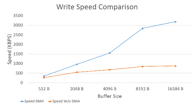
- sped_wR.PNG (21.18 KiB) Viewed 1119 times
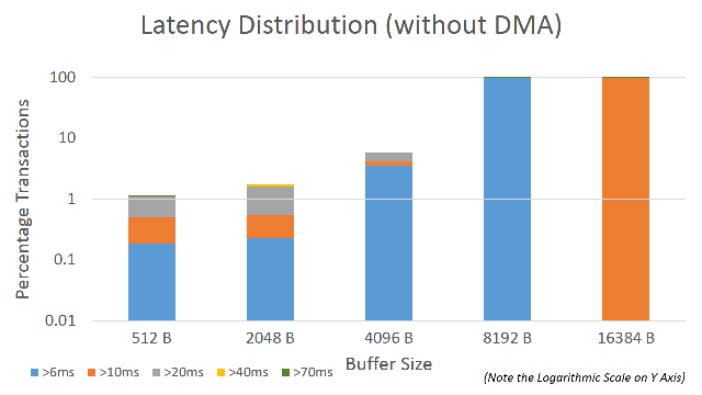
- dma_disT.PNG (22.2 KiB) Viewed 1118 times
viewtopic.php?f=13&t=20&start=120#p17911
[nicolas_soundforce – Sun Aug 06, 2017 5:35 pm] –
I want to read 2 files at the same time. Can I just file.open() 2 files in parallel ? I am having problems at the moment and it doesn’t work as expected.
you need to declare 2 “file” objects, for example file1 and file2, then you can work on each separately:
file1.open()

file2.open()

file2.read...
PR is ongoing: https://github.com/greiman/SdFat/pull/69

