I ported the Arduino VS1003B library with the “hello” example to the STM32F103 MCU.
I published the library to Github https://github.com/Serasidis/STM32duino.
Installation instructions are included in the README.md file on Github.
I intend to organize the ported by me libraries in to the folder Serasidis.
Feature ported libraries (made by me) will be copied into the Serasidis folder also.
If you don’t like the library organization I choose and you prefer an independent folder for every ported library please tell me to change it.
I hope you will enjoy the new ported libray ![]()
Vassilis Serasidis
-= EDIT =-
A short youtube video demonstration of the library can be found here.
maybe is better to have a separate folder for every library under the Serasidis folder. You can also name your libraries with Serasidis prefix like Adafruit does.
I will change it.
I will just copy your files into the repo, because I can’t add them as a sub module from your repo as the files are not in a repo of their own.
If you want to move them to a separate repo, I can remove the files and link via a sub module at a later date,but at least your files will be available for everyone in the mean time
Cheers
Roger
Edit. I have included your files in the repo.
Note I had to change the example as it used PC7 which isnt available on F103C series boards. So that the code now uses PC14 instead
http://www.aliexpress.com/item/VS1003-M … .18.BMZRbQ
I would guess this is a 1053 LC soft board. (So a little hardware mod must be done)

That board uses the VS1003B chip.
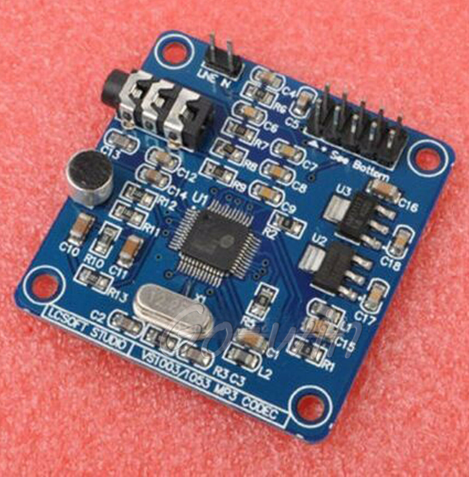
That board uses the VS1053B chip.
The VS1003B_STM library works on both boards (and chips). I have got both boards and I test the library on both of them successfully.
The main differences are that the VS1053B can decode more audio formats (aac) and can decode audio formats at higher bit rates.
So for all people buying this module, please read this article first, because there is a little layout bug in this module (it will start in MIDI mode, not MP3 mode)
http://www.bajdi.com/lcsoft-vs1053-mp3-module/
I forgot I needed to modify my board.
That explains why its not working ![]()
Well, I soldered mine now (but I had to use a usb microscope as the pins were soooo small)
Anyway, I thought I may as well, copy the instructions from the response to that blog entry to here
Although I got my VS1053 working by lodging a piece of wire between pins 33 & 34, I did not think my soldering skills were adequate for making it a permanent solution. Fortunately it turns out there is another solution.
On the VLSI website someone has asked if there is way to exit midi mode. Appraently it is possible to initiate a software re-boot and over-ride the state of pin 34. This is the method described:
“You can detect RTMIDI mode after hardware/software reset by checking AUDATA. If you see 44100/44101, RTMIDI has been activated, and you can write GPIO_DDR=3 and GPIO_ODATA=0, then give software reset to boot into normal decoding mode.”
I have tried it & it works. For information the address of GPIO_DDR is 0xC017 and the address of GPIO_ODATA is 0xC019.
In answer to my earlier question – whether the LCsoft board includes blocking capacitors on the audio out – I am now fairly sure that it does not.
shame they didn’t post some code, as I’m sure they must have written some
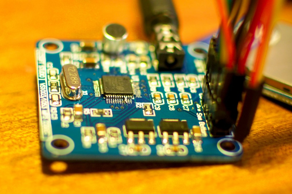
On the above picture the pins 33-34 are soldered together.
On my VS1053B board (LC Technology) the pins 34-35 are soldered together and it works.
As I can see from the VS1053 datasheet the pins are:
GPIO0 | pin 33 | DIO Gen. purp. IO 0 (SPIBOOT), use 100 kΩ pull-down resistor
GPIO1 | pin 34 | DIO General purpose IO
GND | pin 35 | DGND I/O Ground
Now, there is no need in soldering pins 33-34 or 34-35 ![]()
I have made a pull request to Roger for including the patch/fix to the repository.
Can you recommend any cheap board off of ebay or aliexpress from a vendor you already used and was a nice board?
Thanks again.
Can you recommend any cheap board off of ebay or aliexpress from a vendor you already used and was a nice board?
Thanks again.
And big thank you for you software hack method: It’s a little dizzy thing to solder the two pins together, so good there is a possibility to avoid that.
@victor: It seems, that all of the available VS10x3 modules are from “LC soft”. I own a lot of different “LC soft” boards, some of them are ugly soldered, but all of them works. It’s a wise idea to google first the wanted “LC soft xyz module” before buying, some of them have hardware flaws (like the VS1053 one, because the distributor just soldered the VS1053 on the same board layout he used for the VS1003)
I have 2 VS1053 boards, one where I soldered the pins together and one where I didnt.
At the moment, only the board where I soldered then pins together works, but it could be that one board is defective.
I know vasillis tested it on his board, but I’m not sure if thats a VS1003 or a VS1053
1. I tested my VS1053B board with the library without the patch but the with the two pins soldered. The board was worked (I heard the sound).
2. I de-soldered the two pins and I tried again the un-pached library. No sound ![]()
3. I patched the library and I tested again the board. I heard the sound ![]()
I think I will need to solder the pins on my 2nd board, just to prove it is not defective.
I have double checked, by soldering to my 2nd board.
When I solder the pins together it works.
When I remove the solder it doesn’t work.
Are you sure you pushed all your changes back to github ? in the fork of my repo.
The modeSwitch code I have is
void VS1003::modeSwitch(void)

{

//GPIO_DDR

write_register(SCI_WRAMADDR, 0xc017);

write_register(SCI_WRAM, 0x0003);

//GPIO_ODATA

write_register(SCI_WRAMADDR, 0xc019);

write_register(SCI_WRAM, 0x0000);
delay(100);
write_register(SCI_MODE, (1<<SM_SDINEW) | (1<<SM_RESET));
delay(100);
}
Although the library plays the example file, I don’t think any of the code that reads and writes the registers is working.
I can’t seem to set the volume,
and also if I put a return; into the begin() function just after digitalWrite(reset_pin,HIGH); it doesnt make any difference.
e.g.
  // release from reset

digitalWrite(reset_pin,HIGH);
return;
I’ve also changed the constructor, so you can pass an instance of a different SPI channel other than the default which is SPI.
e.g.
Use normal SPI
VS1003 player(PC14, PB10, PA8, PA9); // cs_pin, dcs_pin, dreq_pin, reset_pin, SPI channel - defaults to SPI
However there is a big caveat.
I’ve had a lot of issues with SD
Randomly file.read(buff,length) seems to fail and return -1, and if you attempt to try again immediately it keeps failing
The only hacky work around that seems to have any effect at all is to put in a 10ms delay before retrying.
This hack mostly works, but sometimes, it still ends up hanging sometimes ;-(
But at least it proves you can send a normal MP3 file to the VS1003 and it does play it OK.
I will try and get one of the newer more reliable versions of SD e.g. SdFat to work, but at the moment I’ve only tried Victor’s version of SdFat and it doesn’t work at all for me ![]()
#include <VS1003_STM.h>

#include <SPI.h>

#include <SD.h>
VS1003 player(PC14, PB10, PA8, PA9, SPIClass(2)); // cs_pin, dcs_pin, dreq_pin, reset_pin
/*
* VS1003 development board connected by it's header pins the following way:
*
* GND - GND -
* XDCS - D6 - PB10
* DREQ - D7 - PA8
* XRES - D8 - PA9
* XCS - D9 - PC14
* SCLK - D13 - PA5
* SI - D11 - PA7
* SO - D12 - PA6
* GND - GND -
* 5V - 5V -
*/
void setup ()
{
Serial.begin(115200);
// while (!Serial.available());/// Wait for key entry.. For debugging
// see if the card is present and can be initialized:
while (!SD.begin(PA4))
{
Serial.println("Card failed, or not present");// don't do anything more:
delay(100);
}
Serial.println("card initialized.");
player.begin();
player.modeSwitch(); //Change mode from MIDI to MP3 decoding (Vassilis Serasidis).
player.setVolume(64);
}
int currentFileNum = 0; // Hack because SD only allows one file handle open at a time :-(
void loop()
{
playFile("music.mp3");// Lets just play the music ;-)
delay(1000);
return;
}
#define BUFF_LEN 128
void playFile(char *fileName)
{
uint8_t buff[BUFF_LEN];
File dataFile;
int bytesRead;
int fileSize;
int totalBytesRead = 0;
dataFile = SD.open(fileName);
if (!dataFile)
{
Serial.println("Error opening file");
return;
}
Serial.print("Playing "); Serial.println(fileName);
fileSize = dataFile.size(); // need to know the size of the file
// loop until end of file
while (totalBytesRead != fileSize)
{
do
{
bytesRead = dataFile.read(buff, BUFF_LEN);// try to read a buffers worth
if (bytesRead == -1) // Oops. SD didnt manage to read anything ....
{
delay(10);// Workaround for problem in SD lib.
}
} while (bytesRead == -1);// loop around if last read failed
player.playChunk(buff, bytesRead);
totalBytesRead += bytesRead;// keep track of how much of the file we've played
}
dataFile.close();
}
the patch is loaded fine, also the flac file can be played.
But, the sound is choppy, more choppy than using same VS1053 module using Arduino UNO (little choppy).
I think the choppy sound problem is because SPI transfer problem from SD card library I use same sketch that Rogert posted on this thread.
so it’s using default SD library.
Another suggestion choppy sound is on DREQ pin function.
I was send pull request to Roger repo,
By uncommenting “#define USEFLAC” in VS1003_STM.h the FLAC patch will be loaded at begin time.
Thanks.
i will look at the pull request this morning.
Re: Choppy sound
I initially had problems playing MP3 files, which i tracked down to the issue with the CS pin not working on PA4.
However my MP3 player seems to go wrong after olaying for a few hours, and i suspect the problem is the SD card.
The Micro SD card module I’m using seems to have a level translator chip, but it seems to work ok. But i agree, it would be better to get a micro SD adaptor that doesn’t have the level translator.
I tried the flac patch but there is no sound out VS1053 module
Could you please show me the sketch code and the flac sound file you used for testing the flac plugin ?
Thanks.
This was something on my list to do as well, i.e have an example of using FLAC
I tried the flac patch but there is no sound out VS1053 module
Could you please show me the sketch code and the flac sound file you used for testing the flac plugin ?
In that way, people can run the example without needing SD etc.
You can make the array using a tool like hexy
In that way, people can run the example without needing SD etc.
You can make the array using a tool like hexy
Its only 16k
That cause a problem to the VS1003 library. The examples do not work as they are.
For example, if I replace a part from the hello_STM.ino example code then the example works.
More specific, we have the code
…
//* Example of how to use the VS1003 attached to SPI 2
VS1003 player(PC14, PB10, PA8, PA9, SPIClass(2)); // cs_pin, dcs_pin, dreq_pin, reset_pin, use SPI 2
…
this doesn’t work on maple mini (IDE setup as “Generic STM32F103 C series“).
If I replace it with the code below
…
SPIClass spi2(2); //Create an SPI instance on SPI2 port.
//* Example of how to use the VS1003 attached to SPI 2
VS1003 player(PC14, PB10, PA8, PA9, spi2); // cs_pin, dcs_pin, dreq_pin, reset_pin, use SPI 2
…
it works!
What changes do you suggest me to make on VS1003 library for working correctly ?
EDIT:
The Serial.begin(9600) doesn’t work on Serial port 1
I have to write Serial1.begin(9600);
It seems too hard to migrate to the newest repo… ![]()
in the file: board.cpp in each STM32F1/variants/board xy/
you have at the bottom following entries you can modify for selecting the Serial Port order:
#ifdef SERIAL_USB

DEFINE_HWSERIAL(Serial1, 1);

DEFINE_HWSERIAL(Serial2, 2);

DEFINE_HWSERIAL(Serial3, 3);

DEFINE_HWSERIAL_UART(Serial4, 4);

DEFINE_HWSERIAL_UART(Serial5, 5);

#else

DEFINE_HWSERIAL(Serial, 1);

DEFINE_HWSERIAL(Serial1, 2);

DEFINE_HWSERIAL(Serial2, 3);

DEFINE_HWSERIAL_UART(Serial3, 4);

DEFINE_HWSERIAL_UART(Serial4, 5);

#endif
the Arduino_STM32\STM32F1\variants\generic_stm32f103c\board.cpp file is
/******************************************************************************

* The MIT License

*

* Copyright (c) 2011 LeafLabs, LLC.

*

* Permission is hereby granted, free of charge, to any person

* obtaining a copy of this software and associated documentation

* files (the "Software"), to deal in the Software without

* restriction, including without limitation the rights to use, copy,

* modify, merge, publish, distribute, sublicense, and/or sell copies

* of the Software, and to permit persons to whom the Software is

* furnished to do so, subject to the following conditions:

*

* The above copyright notice and this permission notice shall be

* included in all copies or substantial portions of the Software.

*

* THE SOFTWARE IS PROVIDED "AS IS", WITHOUT WARRANTY OF ANY KIND,

* EXPRESS OR IMPLIED, INCLUDING BUT NOT LIMITED TO THE WARRANTIES OF

* MERCHANTABILITY, FITNESS FOR A PARTICULAR PURPOSE AND

* NONINFRINGEMENT. IN NO EVENT SHALL THE AUTHORS OR COPYRIGHT HOLDERS

* BE LIABLE FOR ANY CLAIM, DAMAGES OR OTHER LIABILITY, WHETHER IN AN

* ACTION OF CONTRACT, TORT OR OTHERWISE, ARISING FROM, OUT OF OR IN

* CONNECTION WITH THE SOFTWARE OR THE USE OR OTHER DEALINGS IN THE

* SOFTWARE.

*****************************************************************************/
/**
* &file wirish/boards/maple_mini/board.cpp
* &author Marti Bolivar <mbolivar&leaflabs.com>
* &brief Maple Mini board file.
*/
#include <board/board.h>
#include <libmaple/gpio.h>
#include <libmaple/timer.h>
/* Roger Clark. Added next to includes for changes to Serial */
#include <libmaple/usart.h>
#include <HardwareSerial.h>
#include <wirish_debug.h>
#include <wirish_types.h>
/* Since we want the Serial Wire/JTAG pins as GPIOs, disable both SW
* and JTAG debug support, unless configured otherwise. */
void boardInit(void) {
#ifndef CONFIG_MAPLE_MINI_NO_DISABLE_DEBUG
disableDebugPorts();
#endif
}
// Note. See the enum of pin names in board.h
extern const stm32_pin_info PIN_MAP[BOARD_NR_GPIO_PINS] = {
{&gpioa, &timer2, &adc1, 0, 1, 0}, /* PA0 */
{&gpioa, &timer2, &adc1, 1, 2, 1}, /* PA1 */
{&gpioa, &timer2, &adc1, 2, 3, 2}, /* PA2 */
{&gpioa, &timer2, &adc1, 3, 4, 3}, /* PA3 */
{&gpioa, NULL, &adc1, 4, 0, 4}, /* PA4 */
{&gpioa, NULL, &adc1, 5, 0, 5}, /* PA5 */
{&gpioa, &timer3, &adc1, 6, 1, 6}, /* PA6 */
{&gpioa, &timer3, &adc1, 7, 2, 7}, /* PA7 */
{&gpioa, &timer1, NULL, 8, 1, ADCx}, /* PA8 */
{&gpioa, &timer1, NULL, 9, 2, ADCx}, /* PA9 */
{&gpioa, &timer1, NULL, 10, 3, ADCx}, /* PA10 */
{&gpioa, &timer1, NULL, 11, 4, ADCx}, /* PA11 */
{&gpioa, NULL, NULL, 12, 0, ADCx}, /* PA12 */
{&gpioa, NULL, NULL, 13, 0, ADCx}, /* PA13 */
{&gpioa, NULL, NULL, 14, 0, ADCx}, /* PA14 */
{&gpioa, NULL, NULL, 15, 0, ADCx}, /* PA15 */
{&gpiob, &timer3, &adc1, 0, 3, 8}, /* PB0 */
{&gpiob, &timer3, &adc1, 1, 4, 9}, /* PB1 */
{&gpiob, NULL, NULL, 2, 0, ADCx}, /* PB2 */
{&gpiob, NULL, NULL, 3, 0, ADCx}, /* PB3 */
{&gpiob, NULL, NULL, 4, 0, ADCx}, /* PB4 */
{&gpiob, NULL, NULL, 5, 0, ADCx}, /* PB5 */
{&gpiob, &timer4, NULL, 6, 1, ADCx}, /* PB6 */
{&gpiob, &timer4, NULL, 7, 2, ADCx}, /* PB7 */
{&gpiob, &timer4, NULL, 8, 3, ADCx}, /* PB8 */
{&gpiob, &timer4, NULL, 9, 4, ADCx}, /* PB9 */
{&gpiob, NULL, NULL, 10, 0, ADCx}, /* PB10 */
{&gpiob, NULL, NULL, 11, 0, ADCx}, /* PB11 */
{&gpiob, NULL, NULL, 12, 0, ADCx}, /* PB12 */
{&gpiob, NULL, NULL, 13, 0, ADCx}, /* PB13 */
{&gpiob, NULL, NULL, 14, 0, ADCx}, /* PB14 */
{&gpiob, NULL, NULL, 15, 0, ADCx}, /* PB15 */
{&gpioc, NULL, NULL, 13, 0, ADCx}, /* PC13 */
{&gpioc, NULL, NULL, 14, 0, ADCx}, /* PC14 */
{&gpioc, NULL, NULL, 15, 0, ADCx}, /* PC15 */
};
extern const uint8 boardPWMPins[BOARD_NR_PWM_PINS] __FLASH__ = {
PB0, PA7, PA6, PA3, PA2, PA1, PA0, PB7, PB6, PA10, PA9, PA8
};
extern const uint8 boardADCPins[BOARD_NR_ADC_PINS] __FLASH__ = {
PB0, PA7, PA6 , PA5 , PA4 , PA3 , PA2 , PA1 , PA0
};
// Note. These defines are not really used by generic boards. They are for Maple Serial USB
#define USB_DP PA12
#define USB_DM PA11
// NOte. These definitions are not really used for generic boards, they only relate to boards modified to behave like Maple boards
extern const uint8 boardUsedPins[BOARD_NR_USED_PINS] __FLASH__ = {
USB_DP, USB_DM
};
/*
* Roger Clark
*
* 2015/05/28
*
* Moved definitions for Hardware Serial devices from HardwareSerial.cpp so that each board can define which Arduino "Serial" instance
* Maps to which hardware serial port on the microprocessor
*/
#ifdef SERIAL_USB
DEFINE_HWSERIAL(Serial1, 1);
DEFINE_HWSERIAL(Serial2, 2);
DEFINE_HWSERIAL(Serial3, 3);
#else
DEFINE_HWSERIAL(Serial, 1);
DEFINE_HWSERIAL(Serial1, 2);
DEFINE_HWSERIAL(Serial2, 3);
#endif
Is there any reason you choose this board for the maple mini?
There are also different pins in the STM32F1 / variants / generic_stm32f103c / board / board.h file. (Maybe the pins are the same: in maple mini they are defined as 26,25 in the generic file as PA9 and PA10 — strange thing)
edit: I cant find if SERIAL_USB is defined, but you can try this:
#ifdef SERIAL_USB

DEFINE_HWSERIAL(Serial1, 2);

DEFINE_HWSERIAL(Serial2, 1);

DEFINE_HWSERIAL(Serial3, 3);

#else

DEFINE_HWSERIAL(Serial, 2);

DEFINE_HWSERIAL(Serial1, 1);

DEFINE_HWSERIAL(Serial2, 3);

#endififdef SERIAL_USB
DEFINE_HWSERIAL(Serial, 1);
DEFINE_HWSERIAL(Serial1, 2);
DEFINE_HWSERIAL(Serial2, 3);
#else
DEFINE_HWSERIAL(Serial, 1);
DEFINE_HWSERIAL(Serial1, 2);
DEFINE_HWSERIAL(Serial2, 3);
#endififdef SERIAL_USB
DEFINE_HWSERIAL(Serial, 1);
DEFINE_HWSERIAL(Serial1, 2);
DEFINE_HWSERIAL(Serial2, 3);
#else
DEFINE_HWSERIAL(Serial, 1);
DEFINE_HWSERIAL(Serial1, 2);
DEFINE_HWSERIAL(Serial2, 3);
#endifThe first UART should be serial1 and so on.
Regarding SerialUSB, if you use the maple mini but do not compile it selecting Maple Mini in the IDE menus, then the USB enumeration will probably now work, as the maple mini has a special circuit to control the 1k5 resistor.
As far as I know, for the Maple mini, Serial has always been the SerialUSB, and Serial1 has always been the first UART, but for other boards it may not have been like that, so the changes beside adding support for SerialUSB to the generic boards, made the naming consistent for all of them, so Serial is always SerialUSB.
About the changes to SPI, Roger did many changes to support setModule. That may have affected what you are describing. Perhaps before the object SPI2 was created in the core, and not now. Not sure, but looks like that.
I think your solution is the right one, create a new object for SPI2, call is spi2 or spiVS or whatever is convenient for you and use it that way.
Roger seems to have assigned the name Serial on the USB_Serial port.
The Hardware Serial ports get the names Serial1, Serial2 and Serial3.
I burned the maple mini bootloader, I connected the USB cable to the maple mini and after a reset I saw a USB serial in my windows devices.
Then, i ran again the Serial.begin(…) and I saw the data on the serial terminal I connected with the usb_serial port.
EDIT
Victor you are very quick! ![]()
It’s controlled via -DSERIAL_USB flag and this is in the Arduino_STM32 / STM32F1 / boards.txt file:
see the differences: first block of each board define:
maple mini
mapleMini.build.board=MAPLE_MINI

mapleMini.build.core=maple

mapleMini.build.cpu_flags=-DMCU_STM32F103CB -DSERIAL_USB

mapleMini.build.variant=maple_mini

mapleMini.upload.usbID=1EAF:0003It’s controlled via -DSERIAL_USB flag and this is in the Arduino_STM32 / STM32F1 / boards.txt file:
see the differences: first block of each board define:
maple mini
mapleMini.build.board=MAPLE_MINI

mapleMini.build.core=maple

mapleMini.build.cpu_flags=-DMCU_STM32F103CB -DSERIAL_USB

mapleMini.build.variant=maple_mini

mapleMini.upload.usbID=1EAF:0003(I’m in real troubles with serial upload on mac, but this is specific to my macbook. Uploads are ok for 3-10x and then I have always to hit the reset button on the board again and again… only thing that helps: reboot of the mac, very annoying thing, but I have too much specific installed programs to reinstall OSX again)
This naming matches the Arduino Leonardo etc which have USB Serial and also Hardware serial.
Re: STLink
We can add this as an option to Maple mini, but you could just select Generic STM32F103C then select F103CB 128k and STLink upload.
BTW. If your library is still broken, the problem could also be the changes to PIN MAP in flash, but this seems less lightly
Send me a PR
If the “Serial” name is assigned to the USB port that would be a small problem in case we don’t want to install a bootloader into the STM32 boards.Without the bootloader we don’t have the “Serial” port. Only the Serial1, Serial2 and Serial3.
Anyway. I plan to use the “STM32duino bootloader” as default in my whole STM32 boards because the flash memory is big enough 64kB + to spend some kBytes in bootloader ![]()
Besides, the bootloader gives us an extra Serial port !
So, it’s worth to use it!
SerialUSB is enabled for the stm32duino-bootloader and the STLink options, but not for Serial uploads
(I can’t recall what the setting was for BMP)
I didnt enable Serial USB for serial uploads as I assume if you are uploading via serial you want to use serial for your debugging, but perhaps thats not a valid argument.
– maple mini
– blue pill
– STM32F103 VET6
– and the ugly board
I had previously erased the STM32 to be empty. The USB serial worked only on the VET6 board. On the other boards, I didn’t see any additional Serial port on my Windows System->Devices when I connected the USB connector to my PC.
After that, I tested the boot-loaders. The boot-loaders work successfully on all above boards.
Only the Ugly board does not auto reboot because of a known USB pull-up resistor. I have every time to reset the chip manually. No problem with that !
I decided to burn the boot-loader on every board I use because of its simplicity. There is no need in additional usb cables/programmers/usb-to-serial converters ![]()
The Ugly board sometimes has other problems, where it will not start from cold boot to run either a sketch (directly at 0x800000) or run the bootloader.
The Ugly board I have does this, and someone else reported this fault.
Sometimes the Ugly board will run a sketch but only if you upload via USB Serial where STM32Flash sends a run 0x800000 command after upload is complete
I think this issue is a hardware problem on the Ugly board, which is possibly that the external oscillator does not start correctly from cold boot
I intend to investigate, when I have time, and perhaps find a software fix for this.
Clock multiplier is 9
USB Clock is 1.5
I’ve not checked the GPIO clock prescaler values but are values in the code which seem to indicate that APBH1 is on a 2 / prescaler and APBH2 is not prescaled i.e (/1)
I’m not sure of the others, but there is only one board that has issues, so I suspect its that board which has a faulty oscillator design
