I am trying to add to phase meter program (#1) another one (#2) which subtracts two rectangular signals.
The program #2 alone is working ok and I have a signal on PC13, when is added to program #1 there is no signal on PC13.
Any idea what I am dooing wrong ?
Program #1
#include <LiquidCrystal.h>

LiquidCrystal lcd(PA0, PA1, PA2, PA3, PA4, PA5);
int pin = PA6;
//////////////////////
int ledPin = PC13;
int u1 = PB10; // input U1 - pulses
int u2 = PB11; //input U2 - pulses
int val = 0; // variable to store the read value
/////////////////////
float rads = 57.29577951; // 1 radian = approx 57 deg.
//float degree = 360;
float degree = 360;
float frequency = 50;
//float frequency = 10000;
float nano = 1 * pow (10, -6); // Multiplication factor to convert nano seconds into seconds
// Define floats to contain calculations
float pf;
float angle;
float pf_max = 0;
float angle_max = 0;
int ctr;
void setup()
{
////////////////////////////////
pinMode(u1, INPUT_PULLDOWN);
pinMode(u2, INPUT_PULLDOWN);
pinMode(PC13, OUTPUT);
////////////////////////////////
pinMode(pin, INPUT);
Serial.begin(9600);
lcd.begin(16, 2);
}
void loop()
{
//////////////////////////
val = (digitalRead(PB10) - digitalRead(PB11)) / 2; // read the input pin
digitalWrite(ledPin, val); // sets the LED to the value
/////////////////////////
for (ctr = 0; ctr <= 4; ctr++) // Perform 4 measurements then reset
{
// 1st line calculates the phase angle in degrees from differentiated time pulse
// Function COS uses radians not Degree's hence conversion made by dividing angle / 57.2958
angle = ((((pulseIn(pin, HIGH)) * nano) * degree) * frequency);
// pf = cos(angle / rads);
if (angle > angle_max) // Test if the angle is maximum angle
{
angle_max = angle; // If maximum record in variable "angle_max"
pf_max = cos(angle_max / rads); // Calc PF from "angle_max"
}
}
if (angle_max > 360) // If the calculation is higher than 360 do following...
{
angle_max = 0; // assign the 0 to "angle_max"
pf_max = 1; // Assign the Unity PF to "pf_max"
}
if (angle_max == 0) // If the calculation is higher than 360 do following...
{
angle_max = 0; // assign the 0 to "angle_max"
pf_max = 1; // Assign the Unity PF to "pf_max"
}
Serial.print(angle_max, 2); // Print the result
Serial.print(",");
Serial.println(pf_max, 2);
//lcd.clear();
lcd.setCursor(0, 0);
lcd.print("PF="); //
lcd.setCursor(4, 0);
lcd.print(pf_max);//
lcd.print(" "); //
lcd.setCursor(0, 1);
lcd.print("Ph-Shift="); //
lcd.setCursor(10, 1);
lcd.print(angle_max);
lcd.print(" ");
//delay(500);
angle = 0; // Reset variables for next test
angle_max = 0;
}
angle = ((((pulseIn(pin, HIGH)) * nano) * degree) * frequency);
If you manage to get that function working stable, then add further pieces to the code.
Anyway, it may be a timely coincidence that after pulseIn() finished, the two pins PB10 and PB11 are always both identical or different, so PC13 will always have the same value, and therefore will not blink.
PB10 andPB11are phase shifted, so after subtraction there are the pulses on oscilloscope ( 5 sec. long )
val = (digitalRead(PB10) - digitalRead(PB11)) / 2; // read the input pinThe strange thing is that program #2 is working only on this pins regardless the name which I am giving to them.
If I put PA6 and PA7 program is not working for those pins but still working with PB10, PB11 = RX3,TX3 ?
int pin = PA6;I asked about the input signal on variable “pin” which was assigned to PA6 in your code, and which was read by pulseIn(). How does this signal look like relative to “V” and “I”?
int ledPin = PC13;

//int ledPin = PB14;  // LED connected to digital pin 13

//int u1 = PB10; // input U1 - pulses

//int u2 = PB11;  //input U2 - pulses
int u1 = PA10; // input U1 - pulses
int u2 = PA9; //input U2 - pulses
int val = 0; // variable to store the read value
void setup()
{
pinMode(u1, INPUT_PULLDOWN);
pinMode(u2, INPUT_PULLDOWN);
pinMode(PC13, OUTPUT);
// pinMode(PB14, OUTPUT);
}
void loop()
{
val = (digitalRead(PB10) - digitalRead(PB11)) / 2; // read the input pin
digitalWrite(ledPin, val); // sets the LED to the button's value
}
val = (digitalRead(PB8) - digitalRead(PB9)) / 2; // read the input pin
int ledPin = PC13;
int val = 0; // variable to store the read value
void setup()
{
pinMode(PC13, OUTPUT);
}
void loop()
{
// make "var" local instead of global, it is more efficient
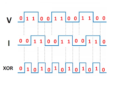
uint8_t val = ( digitalRead(PB8) ^ digitalRead(PB9) ) & BIT0; // XOR of "V" and "I"
digitalWrite(ledPin, val);
}
[Pito – Tue Jul 17, 2018 6:40 am] –
Is this working ok??
val = (digitalRead(PB10) - digitalRead(PB11)) / 2; // read the input pin
[ted – Tue Jul 17, 2018 9:16 am] –
PA6 (input of the meter ) will be connected to PC13 ( output of subtraction I and V )
This means that you want to measure the XOR signal high period, right?
This code will measure the width of both high and low pulses in microsecond resolution.
If you want milliseconds instead, replace “micros” by “millis”.
int ledPin = PC13;

int u1 = PB8; // input U1 - pulses

int u2 = PB9;  //input U2 - pulses
int old_val = 0; // variable to store the old read value
int t; // to measure time
int pulse; // to measure pulse period
void setup()
{
pinMode(u1, INPUT_PULLDOWN);
pinMode(u2, INPUT_PULLDOWN);
pinMode(ledPin, OUTPUT);
t = micros();
}
void loop()
{
uint8_t val = ( digitalRead(u1) ^ digitalRead(u2) ) & BIT0; // XOR of "V" and "I"
if ( old_val != val ) // detect change of the signal
{
old_val = val;
int t0 = micros();
pulse = t0 - t; // here you have the pulse width in microseconds
t = t0; // update time reference for next measurement
// here you can use the "pulse" value, do what you want...
digitalWrite(ledPin, val); // example to show signal change
}
}
[stevestrong – Tue Jul 17, 2018 11:33 am] –[ted – Tue Jul 17, 2018 9:16 am] –
PA6 (input of the meter ) will be connected to PC13 ( output of subtraction I and V )This means that you want to measure the XOR signal high period, right?
Yes,
I run your code, the pulses on PC13 are shaking, the width of them depends to phase shift between I and V = ok, I was trying to get something on LCD, I have: PF=0, the zero is blinking, with delay (to stabilise the reading ) the pulses on PC13 are gone.
That is for 50 Hz, when I change the frequency (100, 1000, Hz) the pulses on PC13 are more not stable.
It is look like there is no sinhronisation with input pulses.
#include <LiquidCrystal.h>

LiquidCrystal lcd(PA0, PA1, PA2, PA3, PA4, PA5);

int ledPin = PC13;

int u1 = PB8; // input U1 - pulses

int u2 = PB9;  //input U2 - pulses
int old_val = 0;  // variable to store the old read value

int t;       // to measure time

int pulse;   // to measure pulse period
void setup()

{

pinMode(u1, INPUT_PULLDOWN);

pinMode(u2, INPUT_PULLDOWN);

pinMode(ledPin, OUTPUT);

t = micros();

lcd.begin(16, 2);

}
void loop()

{

uint8_t val = ( digitalRead(u1) ^ digitalRead(u2) ) & BIT0; // XOR of "V" and "I"
if ( old_val != val ) // detect change of the signal

{

old_val = val;

int t0 = micros();

pulse = t0 - t; // here you have the pulse width in microseconds

t = t0; // update time reference for next measurement
// here you can use the "pulse" value, do what you want...
digitalWrite(ledPin, val); // example to show signal change
}

////////////////////////

lcd.setCursor(0, 0);

lcd.print("PF="); //

lcd.setCursor(4, 0);

lcd.print(val);

//delay(100);

/*

lcd.print(pf_max);//

lcd.print(" "); //

lcd.setCursor(0, 1);

lcd.print("Ph-Shift="); //

lcd.setCursor(10, 1);

lcd.print(angle_max);

lcd.print(" ");

*/

/////////////////////////

}
This line is causing that.
//lcd.print(pulse);
#include <LiquidCrystal.h>

LiquidCrystal lcd(PA0, PA1, PA2, PA3, PA4, PA5);

int ledPin = PC13;

int val = 0;       // variable to store the read value
int old_val = 0;  // variable to store the old read value

int t;       // to measure time

int pulse;   // to measure pulse period
void setup()

{

pinMode(PC13, OUTPUT);

t = micros();

lcd.begin(16, 2);

}
void loop()

{
// make "var" local instead of global, it is more efficient

uint8_t val = ( digitalRead(PB8) ^ digitalRead(PB9) ) & BIT0; // XOR of "V" and "I"

if ( old_val != val ) // detect change of the signal

{

old_val = val;

int t0 = micros();

pulse = t0 - t; // here you have the pulse width in microseconds

t = t0; // update time reference for next measurement
digitalWrite(ledPin, val);

}
////////////////////////

//lcd.setCursor(0, 0);

// lcd.print("PF="); //

// lcd.setCursor(4, 0);

//lcd.print(pulse);
}
[heisan – Tue Jul 17, 2018 11:08 am] –[Pito – Tue Jul 17, 2018 6:40 am] –
Is this working ok??
val = (digitalRead(PB10) - digitalRead(PB11)) / 2; // read the input pin
[ted – Tue Jul 17, 2018 8:08 pm] –
This program is working ok up to 10 kHz when last 4 lines are disabled, activating any of them is causing lost of the pulses on PC13.
#include <LiquidCrystal.h>
LiquidCrystal lcd(PA0, PA1, PA2, PA3, PA4, PA5);
int ledPin = PC13;
int val = 0; // variable to store the read valueint old_val = 0; // variable to store the old read value
int t; // to measure time
int pulse; // to measure pulse periodvoid setup()
{
pinMode(PC13, OUTPUT);
t = micros();
lcd.begin(16, 2);
}void loop()
{// make "var" local instead of global, it is more efficient
uint8_t val = ( digitalRead(PB8) ^ digitalRead(PB9) ) & BIT0; // XOR of "V" and "I"
if ( old_val != val ) // detect change of the signal
{
old_val = val;
int t0 = micros();
pulse = t0 - t; // here you have the pulse width in microseconds
t = t0; // update time reference for next measurementdigitalWrite(ledPin, val);
}////////////////////////
//lcd.setCursor(0, 0);
// lcd.print("PF="); //
// lcd.setCursor(4, 0);
//lcd.print(pulse);}
[ted – Tue Jul 17, 2018 8:18 pm] –[heisan – Tue Jul 17, 2018 11:08 am] –[Pito – Tue Jul 17, 2018 6:40 am] –
Is this working ok??
val = (digitalRead(PB10) - digitalRead(PB11)) / 2; // read the input pin
delayMicroseconds(5); Looking at the signal it is possible to start the time measurement on “V” edges and stop the measurement on “I” edges.
I would try this way:
int u1 = PB10;

int u2 = PB11;

int ledPin = PC13;
volatile uint32_t t, pulse;
void U1_isr() { t = micros(); } // start measurement
void U2_isr() { pulse = micros() - t; } // finish measurement, read value
void blink() { digitalWrite(ledPin, !digitalRead(ledPin)); }
void setup()
{
pinMode(u1,INPUT);
pinMode(u2,INPUT);
pinMode(ledPin, OUTPUT);
pulse = 0; // reset
  attachInterrupt(u1, CHANGE, U1_isr);

attachInterrupt(u2, CHANGE, U2_isr);
}
void loop()
{
if ( pulse>0 ) // new measurement finished
{
uint32_t read_value = pulse;
pulse = 0; // reset
blink();
// process here the "read_value" value
// ...
}
}
I had the same idea, but I did not know how to do it, I think small correction in your program should work.
This is the error,
exit status 1
no matching function for call to ‘attachInterrupt(int&, ExtIntTriggerMode, void (&)())’
caused by this two lines.
attachInterrupt(u1, CHANGE, U1_isr);
attachInterrupt(u2, CHANGE, U2_isr);
  attachInterrupt(u1, U1_isr, CHANGE);

attachInterrupt(u2, U2_isr, CHANGE);
for 0 deg shift: 0V/1.65V
for 45 deg shift: 0V-3.3V/1.65V
0V-3.3V = the first part of the pulse is not stable, it is jumps irregularly from 0V to 3.3V, probably effect of PC noise.
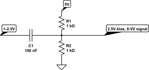
For analog inputs when is used sine wave as a input, the bias 1.65V is needed, for that purpose two resistor voltage divider is used, so if I can get straight line 1.65V instead the pulses the bias can be repleaced by software = no voltage divider ?
By mistake I put a jumper to R pin instead PB11, however if reset pin is able to give 1/2 Vcc on PC13 maybe the code can do the same ?
[stevestrong – Wed Jul 18, 2018 7:00 pm] –
Theoretically you don’t need any divider if the voltage is below 3.3V.
I am talking about negative input, which is not tolerant by microcontrollers
1. What is impedance of your signal source (as that divider does represent a 500ohm load)
2. What is the frequency of your signal (as the 100nF and 500ohm creates a high-pass filter with corner at f=1/(2pi*100e-9*500) = 3kHz, thus signals with f<3kHz will be attenuated..
When you want to AC couple the signal you have to use the bias divider. The capacitor pushes the signal below the 0, therefore you have to get it back with the divider such the mean stays at Vcc/2.
You have to consider the divider resistor’s and capacitor value is critical when you want to measure phase differences of a signal.
I would recommend 2x20kOhm (or 2x18k, or 2x22k), that gives you 10kOhm impedance seen by the ADC (the ADC likes impedance <10k).
Then you have to calculate the Capacitor:
C=1/(2pi*freq*R) [F,Hz,Ohm], where the freq is the lowest frequency of interest, R=10kOhm,
and make the capacitor few times bigger as the value calculated..
For example, (the R1 is output impedance of the signal generator, an example), there is Vcc filtering for the bias divider as well:
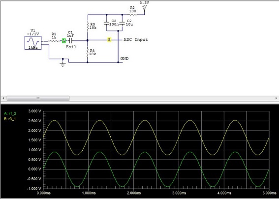
- AC coupled ADC.JPG (58.66 KiB) Viewed 161 times
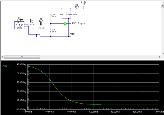
- AC coupled ADC 2.JPG (51.77 KiB) Viewed 163 times
It is known that the pin can be setup as HIGH or LOW (0V/3.3V), when I sow that reset pin can deliver 1/2 Vcc , I thought the software could do this also.
Regarding the last code, I think will work I need to add something to make less sensitive to noise, the pulses on PC13 are nice – no blurring.

