then i hooked up a CR3032 coin cell on VBAT pin on the MM, it seemed to run quite well initially keeping the clock going after removing USB power.
after less than a month the CR3032 drains from some 3+ volts to around 1.5v, i’m rather surprised as VBAT is intended for low power and basically keep the LSE crystal osc and RTC running?
i then tried to measure resistance and voltages, if the coin cell is connected, it reads zero volts across to ground. but if i measure resistance across with a multimeter (VBAT to ground removing the coin cell) i get some 200 ohms.
This is pretty much a short between VBAT and ground?
it seemed the specs gives typical currents of 1 uA, this would seem much greater than 1 uA
would there be any need to put MM into ‘low power modes’ rather than simply disconnecting USB power?
3V/200ohm = 15mA. Cr2032’s capacity is 150mAh.
According to the schematics I saw the Vbat is connected directly to pin Vbat.
If you measure with a multimeter (plus on Vbat, minus on GND), which uses several volts for measuring the resistance, it may happen you open the upper clamp diode (ESD protection at every pin) at the VBat pin and you may measure the forward resistance of the upper clamping diode against VCC/GND (could be 200ohm).
https://training.ti.com/clamp-diodes
With 20uA (doublecheck the datasheet plz) when RTC is running you drain the cr2032 in 150000/20 hours.
it is not easy to identify the tiny features on the boards simply examining them with the naked eye, there might be some shorts at the solder joints etc
actually i’m starting to wonder if disconnecting the usb cable supplying power could have forward biased the clamping diodes, that would increase the currents from microamps to milliamps literally a thousand times higher. if that’s true for the general case it would be bad news as it may mean coin cells won’t last on VBAT pin on MM board designs when power is removed
Simply insert an ammeter between Cr2032+ and Vbat (or Cr2032- and GND) and you may see the current.
I do not have MMini Baite schematics handy (do we have it somewhere?).
The Vbat pin could be setup differently (on silicon) so the clamp diodes (if any) could be arranged such they will not be fw biased when Vcc off and Vbat on. You are right the 3V at Vbat with Vcc at 0V could mess with the upper clamp diode.
PS: My 2 MMini clones when not powered
First shows 7Mohm with multimeter’s + at Vbat pin (and 2Mohms with – at Vbat pin) against GND
Second shows 5Mohm with multimeter’s + at Vbat pin (and 2Mohms with – at Vbat pin) against GND
That would be 3V/6Mohm = ~0.5uA, plus add current of the running RTC, it may get 1.2uA in total.
The Baite’s Vbat goes directly to stm’s pin 1 here.
Btw, MMinis do not have 32kHz RTC crystal mounted, how did you wire it?
- maplemini(1).pdf
- (24.3 KiB) Downloaded 34 times
[Pito – Thu Sep 21, 2017 1:48 am] –
Btw, MMinis do not have 32kHz RTC crystal mounted, how did you wire it?
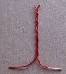
thanks pito, this is tad ugly but it here is the hack, guess it’s about time i solder a new MM ![]()

looks ilke that huge blob of solder at the crystal joints looks pretty bad, would probably need to ‘drain’ all that solder off
VBAT is 3rd pin from the bottom
i think baite is basically MM clone hence presumably the specs would be same as/similar to the original MM
and the usual places to get those 32k crystals, it is a gamble that they even works, but for this piece it works (certainly not that epson 5pf high precision feather weight crystals) ![]()
https://www.ebay.com/sch/i.html?_nkw=32768&_sacat=0
https://www.ebay.com/sch/i.html?_nkw=us … r&_sacat=0
i reused the old tactic of soldering a 32k crystal at pc14, pc15, well that actually works never mind no grounding caps
accordingly one should also have a series resistor with the crystal if one wants the crystal to last, otherwise it may be short lived, but i simply soldered it no resistors
the stm32f103 literally runs *hot*, it is pretty much very hot to touch
3.3v / 130ma ~ 25.3 ohms
and gives a power dissipation of some 0.43 watts
if you go by the specs
http://www.st.com/content/ccc/resource/ … 161566.pdf
section 5.3.5 p42 table 13 max current consumption is a mere 50ma with all pheriperial clocks enabled, this is running more than double that pretty much close to 3x the normal currents
it is somewhat puzzling on the defect density of these ‘cheap’ boards & stm32f103 batches used in manufacture
but despite running hot, it is rather interesting that the chip actually runs the sketch fine driving ili9341 lcd etc
but the steal? no caps they are actually needed but for now i take the short cut as it seem to work

I presume you will end up laying it flat and gluing the crystal to the underside of the board
there is no load capacitor, it is simply the crystal. i’ve been trying to figure out how and where to put 2 load capacitors but i havn’t thought out good solutions. hence i simply have the crystal that took a gamble, surprisingly it ‘just works’, time keeping seem rather accurate but is probably off, i’ve not actually measured that. i simply need the rtc time to timestamp the log files and i could make do with minutes of differences and perhaps sync the rtc say every once in a while (say a week to a month) when i hook it up via usb
I would run a small wire from GND, under the board and perhaps hand solder some 1206 SMD caps to the underside of the board.
1206 SMD parts are not impossible to hand solder.
viewtopic.php?t=671&start=10#p27426
[Pito – Wed May 03, 2017 10:05 am] –
Basically it does not matter what kind of 32kHz resonator you use – it matters how you tune the frequency exactly.
The difference 12.5pF vs. 6pF mostly affects the frequency (because the oscillator inside the chip assumes a specific capacity of the resonator). These ceramic fork 32kHz resonators are made such they have the temperature coef zero around wrist temperature.
In each case you have to tune – the best way is to use a gimmick capacitor (about 3-5mm of twisted 0.2mm magnet wire) at the input side of the oscillator against the ground (wired in parallel to the ceramic capacitor). By selecting the right ceramic cap and cutting off the gimmick wire (by tenths of mm) you can tune the frequency precisely.
1cm of gimmick cap is about 10pF.
1pF makes a difference of seconds/month.
The shorter the gimmick cap the faster the clock.
Not to scale!

unfortunately a baite MM has basically 2 precious ground pins for connection, and i’m yet to figure out how to fit them neatly on a MM/BP, i’d imagine if i use thin magnet wires (awg >30 i.e. thinner than 0.25mm) i’d be able to share the same hole / slot for the crystal contacts. however, for ground pins i’m yet to figure out a convenient way to fit things in neatly
ideally to fit the crystal and the (gimmick) capacitors contraption so that it’d fit nicely as if it is part of the board, but i guess it won’t be easy to work that out
Even if I need to fix the board later, I can just solder end of such wire to the point of existing soldered pin and it is good connection even against ocassional pull-force.
So basically you can attach such wire at the construction time through the hole (one with one pin) or maybe like 4-5 later to the same soldering point (or combine the methods).
Ofcourse connecting far away pins with the wire / capacitor would lead to some capacity to any and all paths it cross over the PCB, but it probably matter ony for noise in analog and for computing the result capacity – which would be more like experimented-out, than exactly computed anyway)
![[SOLVED] Discovery STM32F100RB — Trouble with timers and library structure](https://sparklogic.ru/wp-content/uploads/2019/11/st-stm32vl-discovery-90x90.jpg)

