EDIT: I have the sleep and deepsleep working, see later posts in this thread. What I still need to do is tidy up the code, and produce a clean, commented, easy to read version.
For your amusement here is a sketch that attaches the seconds interrupt, to blink the led and send a dot to the serial consiole and triggers alarms every 10 seconds. This works fine, until you put the beast to sleep. It is just a rough guideline, not anything solid.
//

// Example of sleep and deepsleep modes

//

//
#define BOARD_LED_PIN PB0
//#define BOARD_LED_PIN PC13
// Strictly speaking only the RTC crystal is necessary for this code to work.
#define BOARD_HAS_WORKING_RTC_CRYSTAL true
#define BOARD_HAS_WORKING_RTC_BATTERY true
// Define the Base address of the RTC registers (battery backed up CMOS Ram), so we can use them for config of touch screen or whatever.
// See http://stm32duino.com/viewtopic.php?f=15&t=132&hilit=rtc&start=40 for a more details about the RTC NVRam
// 10x 16 bit registers are available on the STM32F103CXXX more on the higher density device.
#define BKP_REG_BASE (uint32_t *)(0x40006C00 +0x04)
// Defined for power and sleep functions pwr.h and scb.h
#include <libmaple/pwr.h>
#include <libmaple/scb.h>
// These are possibly defined somewhere but I couldn't find them.
// System Control Register Bits. See...
// http://infocenter.arm.com/help/index.jsp?topic=/com.arm.doc.dui0497a/Cihhjgdh.html
#define SCB_SCR_SLEEPDEEP 4 // This register bit controls deepsleep(1) or sleep(0)
#define SCB_SCR_SLEEPONEXIT 2 // This register bit controls sleeponexit. i.e. do we go back to sleep immediately after serviceing the interrupt, or go back to the main loop.
#define SCB_SCR_SEVONPEND 16 // Controls Send Event on Pending bit:
// Set up RTC and choose one of the available clocks.
// The HSE/128 works in all boards
// Boards with a 32kHz RTC crystal fitted can choose any clock (but I suggest using LSE as this is the 32kHz clock).
//
#include <RTClock.h>
#ifdef BOARD_HAS_WORKING_RTC_CRYSTAL true
RTClock rt(RTCSEL_LSE);
#else
RTClock rt(RTCSEL_HSE);
// Alternatives...
// RTClock rt(RTCSEL_LSI);
// RTClock rt; // this starts HSE clock as a default.
#endif
bool ledOff = true;
bool alarmTriggeredFlag = false;
bool secInterruptFlag = false;
bool deepSleepFlag = false;
long int globSecCnt = 0; // Number of secondsInterrupts this session.
// NOTE: globSecCnt is *not* preserved in deepsleep as the system restarts (ram contents are lost) after deepsleep.
// The RTC of course does keep an accurate count of seconds.
// Caveat, RTC time, and the RTC battery backed registers are preserved in deepsleep only if there is a voltage source (generally a battery) connected to vBat.
// Some boards have vBat connected to VDD,the main STM32FXX 3V3 power supply so their RTC will keep working so long as the main power is preserved.
// Flash is always preserved in deepsleeep, so writing to flash would be the best way to preserve config in excess of the
// 14 bytes offered by the RTC when in deepsleep.
long int alarmDelay = 15; // Seconds between restarts if using deepsleep, or time of first alarm if using sleep (subsequent sleeps can be set in the loop() section.
struct tm time_tm, *tm_ptr; // This is a structure with date and time fields, used to set the time if BOARD_HAS_WORKING_RTC_CRYSTAL is false.
int numFlashes = 1;
// Create USB serial_debug port
USBSerial serial_debug;
void setup() {
// This may be needed if we find the sys clock is incorrect after wakeup
// Set up clock, PLL an multiplier
// Chose RCC_PLLMUL_9 and RCC_PRESCALER_USB, 1.5 for 72MHz fom 8MHz crystal (standard STM32F103 speeds on most clone boards).
// Chose RCC_PLLMUL_6 and RCC_PRESCALER_USB, 1 for 48MHz lower power from 8MHz crystal (standard STM32F103 speeds on most clone boards)
// rcc_clk_init(rcc_sysclk_src sysclk_src, rcc_pllsrc pll_src, rcc_pll_multiplier pll_mul)
// rcc_clk_init(RCC_CLKSRC_HSI, RCC_PLLSRC_HSE , RCC_PLLMUL_9);
// rcc_switch_sysclk(rcc_sysclk_src sysclk_src)
// DANGER - here be dragons.
// Switch to external 8MHz clock, set multipler, switch back to internal
// rcc_switch_sysclk(RCC_CLKSRC_HSE);
// rcc_clk_init(RCC_CLKSRC_HSI, RCC_PLLSRC_HSE , RCC_PLLMUL_2);
// rcc_clk_init(RCC_CLKSRC_HSI, RCC_PLLSRC_HSE , RCC_PLLMUL_16);
// rcc_switch_sysclk(RCC_CLKSRC_HSI);
//
// rcc_clk_init(RCC_CLKSRC_HSE, RCC_PLLSRC_HSE , RCC_PLLMUL_16);
// rcc_switch_sysclk(RCC_CLKSRC_HSE);
// Likewise for the USB prescaler
// rcc_set_prescaler(rcc_prescaler prescaler, uint32 divider)
// rcc_set_prescaler(RCC_PRESCALER_USB, 1.5);
// rcc_set_prescaler(RCC_PRESCALER_USB, 1.5);
pinMode(BOARD_LED_PIN, OUTPUT);//setup our alive pin.
digitalWrite(BOARD_LED_PIN, ledOff);
// If we have a working RTC crystal, we do nothing, this will simply preserve the current time, otherwise with no working RTC crystam we set something sane in the RTC instead.
if (!BOARD_HAS_WORKING_RTC_CRYSTAL)
{
setSaneRTC();
}
// Attempt to set up 48MHz and 1x USB clock
clockARM48();
numFlashes = 1;
for ( int x = 0; x < 10; x++ )
{
serial_debug.println("Flash48!");
flashLED(numFlashes);
}
// Back to 72MHz and 1.5x USB clock
clockARM72();
;
numFlashes = 1;
for ( int x = 0; x < 10; x++ )
{
serial_debug.println("Flash72!");
flashLED(numFlashes);
}
delay(5000);
// If not using deepsleep, you can enable the secondsInterrupt ISR, and wakeup every second. This is less energy efficent obviously.
// It has an effect on deepsleep in this sketch, so can not be left configured.
// rt.attachSecondsInterrupt(&serviceSecondsInterrupt); //Set the SecondsInterrupt ISR to fire (every second obviously).
// Set the inital alarm timer to wakeup now + alarmDelay seconds
time_t nextAlarm = (rt.getTime() + alarmDelay); // Calculate from time now.
rt.createAlarm(&AlarmFunction, nextAlarm); // Set the alarm to trigger (alarmDelay) later...
}
void loop() {
// Set loop alarm delay (seconds).
alarmDelay = 20;
//Note: If we use deepsleep, the rest of this code will do nothing since we never actually get the alarmTriggeredFlag set.
// The perhaps less than obvious reason for this is that deepsleep restarts the CPU on wakeup, so the flag is cleared.
// Check Alarm triggered flag
if (alarmTriggeredFlag)
{
// 3 flashes.. we came back from low power mode without restarting.
numFlashes = 3;
flashLED(numFlashes);
delay(2000);
} else {
// 8 quick flashes to prove we got here, either at power on or deepsleep power on.
numFlashes = 8;
flashLED(numFlashes);
delay(1000);
}
// Check seconds interrupt flag
if (secInterruptFlag)
{
// We dont have much time here.. the next interrup is due in 1 second
// Do *something* to prove we were here.
numFlashes = 1;
flashLED(numFlashes);
}
// rcc_switch_sysclk(RCC_CLKSRC_HSE);
// delay(1);
// Sleep mode - save some power while we wait for the next alarm.
// if deepSleepFlag=true we deepsleep, otherwise, we just sleep
sleepMode(deepSleepFlag);
deepSleepFlag = !deepSleepFlag;
delay(1000);
}
void serviceSecondsInterrupt()
{
if (rtc_is_second())
{
globSecCnt++;
secInterruptFlag = true;
toggleLED();
}
}
void AlarmFunction () {
// This appears to be needed here, We find the sys clock is incorrect (slow) after wakeup.
// Set up clock, PLL and multiplier anything from RCC_PLLMUL_2..RCC_PLLMUL_16
// Chose RCC_PLLMUL_9 and RCC_PRESCALER_USB, 1.5 for 72MHz fom 8MHz crystal (standard STM32F103 speeds on most clone boards).
// Chose RCC_PLLMUL_6 and RCC_PRESCALER_USB, 1 for 48MHz lower power from 8MHz crystal (standard STM32F103 speeds on most clone boards)
// rcc_clk_init(rcc_sysclk_src sysclk_src, rcc_pllsrc pll_src, rcc_pll_multiplier pll_mul)
// Experimental current draw results typical valuse with a power and blink LEDs lit subtract approx 4mA for the LED, 2mA for the regulator, and say 1mA for the resistance of the leads. .
// The halted CPU should be drawing <300uA With the processor halted, the meter was reading 7.9mA, so allowing for the quality of the meter, and other environmental issues.
// the results below look pretty accurate.. to within 1mA. Close enough for government work :¬)
// These look similar to the ST datasheet http://www.st.com/web/en/resource/technical/document/datasheet/CD00161566.pdf
// (Page 42 & 43)
// External (RCC_CLKSRC_HSE) 8MHz, no multiplier.
// rcc_switch_sysclk(RCC_CLKSRC_HSE); // 8MHz => 16mA -- datasheet value @20 deg. C => between 5.5 and 6mA
// Internal (RCC_CLKSRC_HSI) 8MHz x RCC_PLLMUL_x multiplier.
// rcc_clk_init(RCC_CLKSRC_HSI, RCC_PLLSRC_HSE , RCC_PLLMUL_2); // 16MHz => 21 mA -- datasheet value => between 10 and 11mA
// Default configuration 72MHz
// rcc_clk_init(RCC_CLKSRC_HSI, RCC_PLLSRC_HSE , RCC_PLLMUL_9); // 72MHz => 48 mA -- datasheet value => between 40 and 41mA
// rcc_clk_init(RCC_CLKSRC_HSI, RCC_PLLSRC_HSE , RCC_PLLMUL_16); // 128MHz => 69 mA -- no data.
// rcc_switch_sysclk(RCC_CLKSRC_HSE);
rcc_clk_init(RCC_CLKSRC_HSI, RCC_PLLSRC_HSE , RCC_PLLMUL_16); // 128MHz => 69 mA -- Overclocked no STM data available.
//rcc_clk_init(RCC_CLKSRC_HSE, RCC_PLLSRC_HSE , RCC_PLLMUL_2); //
//rcc_switch_sysclk(RCC_CLKSRC_HSI);
// Likewise for the USB prescaler
// rcc_set_prescaler(rcc_prescaler prescaler, uint32 divider)
// rcc_set_prescaler(RCC_PRESCALER_USB, 1.5);
// rcc_set_prescaler(RCC_PRESCALER_USB, 1.5);
alarmTriggeredFlag = true;
// We get here when the alarm triggers.
// We have all the time in the world in here, till we set the next alarm and exit.
numFlashes = 4;
flashLED(numFlashes);
//Note: these flashes are at whichever clock speed we chose above, The milis() will therefore only be millis() if the clock is 72 mHz
delay(3000); // Wait long enough to see the current reading on the multimeter. At 128MHz this will be pretty brief, but at 8MHz it will take forever :¬)
//Reset alarm to trigger another interrupt in alarmDelay seconds...
time_t now = rt.getTime();
rt.setAlarmTime(now + alarmDelay);
}
void toggleLED ()
{
ledOff = !ledOff;
digitalWrite(BOARD_LED_PIN, ledOff);
}
// Set a relatively sane RTC time to work from if there is no battery or RTC crystal fitted.
void setSaneRTC()
{
// Set the RTC time to 12:45:00 18th Oct 2015 using a tm struct.
// see http://www.cplusplus.com/reference/ctime/tm/
time_tm.tm_hour = 12;
time_tm.tm_min = 45;
time_tm.tm_sec = 0;
time_tm.tm_mday = 18;
time_tm.tm_mon = 10;
time_tm.tm_year = 115;// Per standard C "struct tm" ... years since 1900
rt.setTime(&time_tm);
}
// Quick (N times) flashes on the LED
// Timing will be in mS *only* if the processor clock is running at the correct rate.
void flashLED(int numFlashes)
{
int flashLen = 80; //mS ?
ledOff = true;
if (numFlashes > 0)
{
for (int i = 0 ; i < numFlashes; i++ )
{
for (int j = 0; j < 2; j++)
{
toggleLED();
delay(flashLen);
}
}
}
}
void sleepMode(bool deepSleepFlag)
{
// Clear PDDS and LPDS bits
PWR_BASE->CR &= PWR_CR_LPDS | PWR_CR_PDDS | PWR_CR_CWUF;
// Set PDDS and LPDS bits for standby mode, and set Clear WUF flag (required per datasheet):
PWR_BASE->CR |= PWR_CR_CWUF;
PWR_BASE->CR |= PWR_CR_PDDS;
  // Enable wakeup pin bit.

PWR_BASE->CR |=  PWR_CSR_EWUP;
// Low-power deepsleep bit.
// PWR_BASE->CR |= PWR_CR_LPDS;
// System Control Register Bits. See...
// http://infocenter.arm.com/help/index.jsp?topic=/com.arm.doc.dui0497a/Cihhjgdh.html
if (deepSleepFlag)
{ // Experimental
// Set Power down deepsleep bit.
PWR_BASE->CR |= PWR_CR_PDDS;
// Unset Low-power deepsleep.
PWR_BASE->CR &= ~PWR_CR_LPDS;
// Set sleepdeep in the system control register - if set, we deepsleep and coldstart from RTC or pin interrupts.
SCB_BASE->SCR |= SCB_SCR_SLEEPDEEP;
} else {
// Unset Power down deepsleep bit.
PWR_BASE->CR &= ~PWR_CR_PDDS;
// set Low-power deepsleep.
PWR_BASE->CR |= PWR_CR_LPDS;
/*
* PWR_CR_PDDS
Power down deepsleep.
PWR_CR_LPDS
Low-power deepsleep.
*/
// Unset sleepdeep in the system control register - if not set then we only sleep and can wake from RTC or pin interrupts.
SCB_BASE->SCR |= SCB_SCR_SLEEPDEEP;
// Low-power deepsleep bit.
}
// Set end Event on Pending bit: - enabled events and all interrupts, including disabled interrupts, can wakeup the processor.
// SCB_BASE->SCR |= SCB_SCR_SEVONPEND;
// Set SLEEPONEXIT -Indicates sleep-on-exit when returning from Handler mode to Thread mode -
// if enabled, we will effectively sleep from the end of one interrupt till the start of the next.
// SCB_BASE->SCR |= SCB_SCR_SLEEPONEXIT;
// Now go into stop mode, wake up on interrupt
asm(" wfi");
}
void clockARM48()
{
// Attempt to set up 48MHz and 1x USB clock
rcc_switch_sysclk(RCC_CLKSRC_HSE);
rcc_set_prescaler(RCC_PRESCALER_USB, 1);
rcc_clk_init(RCC_CLKSRC_HSI, RCC_PLLSRC_HSE , RCC_PLLMUL_6);
rcc_clk_init(RCC_CLKSRC_HSI, RCC_PLLSRC_HSE , RCC_PLLMUL_6);
rcc_switch_sysclk(RCC_CLKSRC_HSI);
//rcc_switch_sysclk(RCC_CLKSRC_PLL);
}
void clockARM72()
{
// Attempt to set up 72MHz and 1x USB clock
rcc_switch_sysclk(RCC_CLKSRC_HSE);
rcc_set_prescaler(RCC_PRESCALER_USB, 1.5);
rcc_clk_init(RCC_CLKSRC_HSI, RCC_PLLSRC_HSE , RCC_PLLMUL_9);
// rcc_switch_sysclk(RCC_CLKSRC_HSI);
rcc_switch_sysclk(RCC_CLKSRC_PLL);
}
Standby mode saves power by shutting down the MCU completely. It shut’s down pretty much every clock, so you need to make sure of 1st, is the RTC using the right clock source? 2nd, does standby mode require anything else special to wake with RTC?
From you code looks like you are trying to go to standby mode, I would try to first get it to the low power mode that stops the cpu, but not the clocks, and see if even that fails or that works. If that fails too, it is something other than the clock source, if it works then may be something related to the clock source.
I dont remember the names of the modes and the details on each from the top of my head, but I hope the ideas above help.
See http://static.leaflabs.com/pub/leaflabs … i/scb.html for the maple take on this arrangement.
/* System control register (SCB_SCR) */
#define SCB_SCR_SEVONPEND (1U << 4)
#define SCB_SCR_SLEEPDEEP (1U << 2)
#define SCB_SCR_SLEEPONEXIT (1U << 1)
SCB_BASE->SCR |= SCB_SCR_SLEEPDEEP;
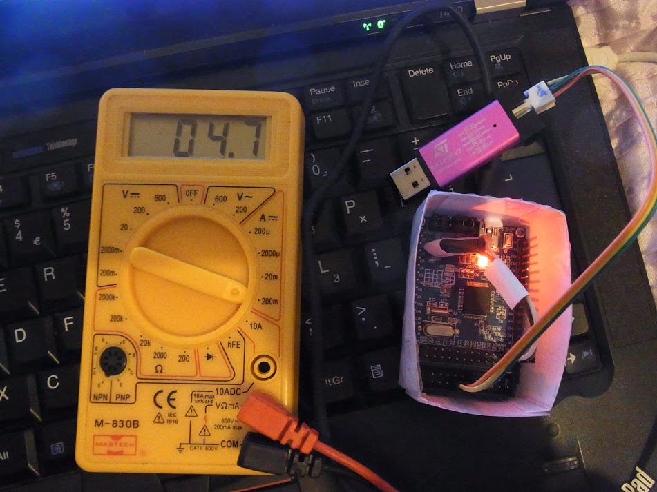
The current drops to a rather more useful 4.7mA, roughly the current drawn by the power LED I suspect, (but since I don’t have the sketch waking up correctly, this is not much use.. yet…)
4.7mA looks like the target to aim for here. That would allow me to run the board for 25 days on a single 2500mAH lipo. Longer still if I remove the power LED. With sleep, as opposed to deep_sleep we can run the board for about 4 days, and with no sleep, it will run for about 2.5 days. Reducing the clock speed would also help here, since the application I have in mind wont require much in the way of processing except when calculating sunrise, sunset, etc. a task that only needs to be performed once per day. Of course if I have a display attached, that too will draw current, with the Nokia 5110 style displays and some others, this can be in the single digit mA range, so the processor is the main power hog.
I added…
// Enable wakeup pin bit.
PWR_BASE->CR |= PWR_CSR_EWUP;
It seems that if you sleep on an idea, inspiration often strikes… ![]()
This means 20+ days between recharges of a single 2600mAh lipo might be realistic.
Since my lipo pack is actually 4x2600mAh lipos, that gives me around 100 days of standby.
I doubt I’ll ever leave a camera sitting unattended for 3 months, furthermore when the camera is shooting, it will probably draw a peak of around 1 amp when starting up, slightly less when shooting, so it will eat the battery much quicker than that. In practical terms.
This suggests that since I can currently shoot for around 24hrs or more with the pack with no power saving, now I should be able to shoot for 24 hrs spread over a 100 day period, which should allow say half an hour every day for 50 days.
Still a long way to go before I have this in a usable format… but I’m making progress. ![]()
EDIT: an interesting effect of the code is that every time it wakes up, it re-enumerates the USB device.. syslog snippet below…
Oct 19 12:11:15 ahull-T430 mtp-probe: checking bus 1, device 103: "/sys/devices/pci0000:00/0000:00:1a.0/usb1/1-1/1-1.2"

Oct 19 12:11:15 ahull-T430 mtp-probe: bus: 1, device: 103 was not an MTP device

Oct 19 12:11:17 ahull-T430 kernel: [165300.600993] usb 1-1.2: USB disconnect, device number 103

Oct 19 12:11:17 ahull-T430 kernel: [165300.798817] usb 1-1.2: new full-speed USB device number 104 using ehci-pci

Oct 19 12:11:17 ahull-T430 kernel: [165300.892955] usb 1-1.2: New USB device found, idVendor=1eaf, idProduct=0004

Oct 19 12:11:17 ahull-T430 kernel: [165300.892959] usb 1-1.2: New USB device strings: Mfr=1, Product=2, SerialNumber=0

Oct 19 12:11:17 ahull-T430 kernel: [165300.892960] usb 1-1.2: Product: Maple

Oct 19 12:11:17 ahull-T430 kernel: [165300.892962] usb 1-1.2: Manufacturer: LeafLabs

Oct 19 12:11:17 ahull-T430 kernel: [165300.893311] cdc_acm 1-1.2:1.0: ttyACM3: USB ACM device

Oct 19 12:11:17 ahull-T430 mtp-probe: checking bus 1, device 104: "/sys/devices/pci0000:00/0000:00:1a.0/usb1/1-1/1-1.2"

Oct 19 12:11:17 ahull-T430 mtp-probe: bus: 1, device: 104 was not an MTP device

Oct 19 12:11:23 ahull-T430 kernel: [165306.488231] usb 1-1.2: USB disconnect, device number 104

Oct 19 12:11:23 ahull-T430 kernel: [165306.685953] usb 1-1.2: new full-speed USB device number 105 using ehci-pci

Oct 19 12:11:23 ahull-T430 kernel: [165306.779441] usb 1-1.2: New USB device found, idVendor=1eaf, idProduct=0003

Oct 19 12:11:23 ahull-T430 kernel: [165306.779445] usb 1-1.2: New USB device strings: Mfr=1, Product=2, SerialNumber=3

Oct 19 12:11:23 ahull-T430 kernel: [165306.779447] usb 1-1.2: Product: Maple 003

Oct 19 12:11:23 ahull-T430 kernel: [165306.779448] usb 1-1.2: Manufacturer: LeafLabs

Oct 19 12:11:23 ahull-T430 kernel: [165306.779449] usb 1-1.2: SerialNumber: LLM 003

Oct 19 12:11:23 ahull-T430 mtp-probe: checking bus 1, device 105: "/sys/devices/pci0000:00/0000:00:1a.0/usb1/1-1/1-1.2"

Oct 19 12:11:23 ahull-T430 mtp-probe: bus: 1, device: 105 was not an MTP device

Oct 19 12:11:25 ahull-T430 kernel: [165308.279998] usb 1-1.2: USB disconnect, device number 105

Oct 19 12:11:25 ahull-T430 kernel: [165308.477682] usb 1-1.2: new full-speed USB device number 106 using ehci-pci

Oct 19 12:11:25 ahull-T430 kernel: [165308.571839] usb 1-1.2: New USB device found, idVendor=1eaf, idProduct=0004

Oct 19 12:11:25 ahull-T430 kernel: [165308.571844] usb 1-1.2: New USB device strings: Mfr=1, Product=2, SerialNumber=0

Oct 19 12:11:25 ahull-T430 kernel: [165308.571846] usb 1-1.2: Product: Maple

Oct 19 12:11:25 ahull-T430 kernel: [165308.571848] usb 1-1.2: Manufacturer: LeafLabs

Oct 19 12:11:25 ahull-T430 kernel: [165308.572195] cdc_acm 1-1.2:1.0: ttyACM3: USB ACM device
If we do have the standby current at <370uA that represents potentially 1171+ days of standby, or in excess of 3 years. If we are down at the 4uA level, then we are looking at more like 300 years
Low power
High Power
My UglyBoard wont run the sketch.
I suspect this is down to the fact that it doesn’t correctly re-enumerate the USB port, as we have seen in the past. It starts up, blinks the LED, then sulks.
I do have a Blue Pill that I can whip the LED off, but these have a micro USB connector rather than a mini one, so my hacked together USB current measuring lead will require surgery to add a micro USB connector.. Unless I can find a converter in my large stash of random junk in boxes well ordered workshop of course.. ![]()
I think you had the idea before of doing a low power library, we should probably work on that one day, or at least compile the different threads with low power tests so we can go back. This one will be really useful for anyone trying to use the RTC to wake up.
I believe the core now runs fine at 48Mhz if you want to try it, at the very least the usb does because I tested it. You need to change the USB to use div1, and the pll to use x6 instead of x9, I believe the file is boards.cpp or board_setup.cpp. The details are in the thread about the GD.
Roger modified most if not all the core functions that depend on the frequency so most should work fine at 48Mhz. I believe I tested usb, and TFT, but I dont completely remember.
I have been busy finishing a guitar and have not played with the stm boards in over a month, so nothing is fresh in my mind anymore…
If you need to keep variables from standby but not from reset, you could have your code save variables to i2c eeprom or flash, then go to standby, and when the code starts check if that flag was set to decide if it is a wake up or a reset to act one way or the other. The flag information is in the datasheet in the low power modes section, if I remember right at the end of the section. I do not remember thought if there is a flag for each power saving mode, or just for standby, but in the other modes code start exactly where it left, so you know exactly what was executing before waking up, no need to have a flag for those I guess.
I also had a play with changing the RCC_CLKSRC_HSI, RCC_PLLSRC_HSE , RCC_PLLMUL_X clock source parameters in the Alarm interrupt service routine.
I can successfully change the clock (in this routine only) on the fly… so I can trudge along at 16MHz or zip along at 128MHz (no smoke.. yet)…
  // Experimental current draw results typical values from my STM2F103R8T6 board, with the power and blink LEDs lit.

// rcc_clk_init(RCC_CLKSRC_HSI, RCC_PLLSRC_HSE , RCC_PLLMUL_2);      // 16MHz  => 21 mA

// rcc_clk_init(RCC_CLKSRC_HSI, RCC_PLLSRC_HSE , RCC_PLLMUL_9);      // 72MHz  => 48 mA

// rcc_clk_init(RCC_CLKSRC_HSI, RCC_PLLSRC_HSE , RCC_PLLMUL_16);    // 128MHz => 69 mA
Summary of the results below. They agree with the datasheet (Page 42 and 43), within a reasonable margin. 8mA (not including the LED etc) for an 8MHz ARM processor will do for me ![]()
  // Experimental current draw results typical values with power and/or blink LEDs lit.

//  subtract approx 4mA for the LED, 2mA for the regulator, and say 1mA for the resistance of the leads. .

// The halted CPU should be drawing <300uA With the processor halted, the meter was reading 7.9mA, so allowing for the quality of the meter, and other environmental issues.

// the results below look pretty accurate.. to within 1mA. Close enough for government work :¬)
// These look similar to the ST datasheet http://www.st.com/web/en/resource/technical/document/datasheet/CD00161566.pdf
// (Page 42 & 43)
// External (RCC_CLKSRC_HSE) 8MHz, no multiplier.
// rcc_switch_sysclk(RCC_CLKSRC_HSE); // 8MHz => 16mA -- datasheet value @20 deg. C => between 5.5 and 6mA
// Internal (RCC_CLKSRC_HSI) 8MHz x RCC_PLLMUL_x multiplier.
// rcc_clk_init(RCC_CLKSRC_HSI, RCC_PLLSRC_HSE , RCC_PLLMUL_2); // 16MHz => 21 mA -- datasheet value => between 10 and 11mA
// Default configuration 72MHz
// rcc_clk_init(RCC_CLKSRC_HSI, RCC_PLLSRC_HSE , RCC_PLLMUL_9); // 72MHz => 48 mA -- datasheet value => between 40 and 41mA
// rcc_clk_init(RCC_CLKSRC_HSI, RCC_PLLSRC_HSE , RCC_PLLMUL_16); // 128MHz => 69 mA -- no data.
We added a function that can disable the clock in any peripheral. We needed it to change the usb port speed in the GD, as the clock needs to be disabled before changing the divider, and I have not tested it in anything else, but the function is 99% the same as the one used to enable all the clocks, so I am pretty confident it works to disable the clock in any peripheral. The datasheet shows somewhere how much is the difference between all peripherals enabled and all disabled, and is a few mA. If you dont need any peripheral, I would disable the clock of those at the start of the sketch. Even peripherals that you use, you can disable their clock by default and enable it again when you need them, their registers stay valid with clock disabled according to the datasheet. That may give you a few more mA back.
I forgot the name of the function, but is used right in the file that sets the PLL multiplier, just a few lines down, it disables the USB clock, then changes the divider, and enables it again.
http://www.stm32duino.com/viewtopic.php?f=45&t=667
conclusions are interesting
stephen
Added a couple of crude functions to swap between 48MHz and 72MHz, the only peripheral clock that is adjusted is the USB clock, so use with caution.
At 48MHz millis() etc will all be slowed down, any other timings may well also be shot.
A more robust approach would involve taking a snapshot of the current peripheral clocks and adjusting those accordingly for the new PLL clock speed.
I should also check to see if the clock has settled before swapping, so these simple functions may glitch and leave you at the wrong clock speed.
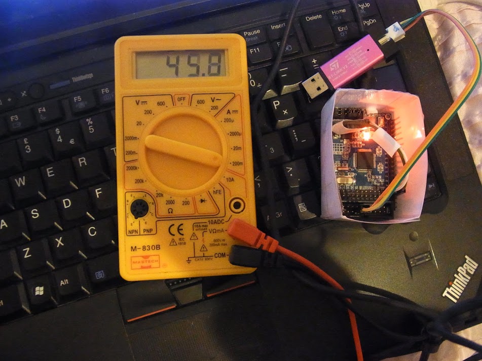
I’m heading in the right direction however. Sketch now boots, slows down to 48MHz (current drops to 20mA), blinks and writes Blink48! 100 times to the USB serial, speeds back up to 72MHz (current goes up to 45mA) and blinks and writes Blink72! 100 times to USB, then goes to sleep. Wakes up, runs at 128MHz in the Alarm loop (more blinks, current peaks at 65mA), goes to deepsleep, restarts (USB drops), and repeats.
Note:This is work in progress, so may be unreliable.
Since I now have control of the USB port at two different clock speeds I can do a bit more debugging.
//

// Example of RTC alarm triggering and changing clocks on the fly

//

//
#define BOARD_LED_PIN PB0
//#define BOARD_LED_PIN PC13
// Strictly speaking only the RTC crystal is necessary for this code to work.
#define BOARD_HAS_WORKING_RTC_CRYSTAL true
#define BOARD_HAS_WORKING_RTC_BATTERY true
// Define the Base address of the RTC registers (battery backed up CMOS Ram), so we can use them for config of touch screen or whatever.
// See http://stm32duino.com/viewtopic.php?f=15&t=132&hilit=rtc&start=40 for a more details about the RTC NVRam
// 10x 16 bit registers are available on the STM32F103CXXX more on the higher density device.
#define BKP_REG_BASE (uint32_t *)(0x40006C00 +0x04)
// Defined for power and sleep functions pwr.h and scb.h
#include <libmaple/pwr.h>
#include <libmaple/scb.h>
// These are possibly defined somewhere but I couldn't find them.
// System Control Register Bits. See...
// http://infocenter.arm.com/help/index.jsp?topic=/com.arm.doc.dui0497a/Cihhjgdh.html
#define SCB_SCR_SLEEPDEEP 4 // This register bit controls deepsleep(1) or sleep(0)
#define SCB_SCR_SLEEPONEXIT 2 // This register bit controls sleeponexit. i.e. do we go back to sleep immediately after serviceing the interrupt, or go back to the main loop.
#define SCB_SCR_SEVONPEND 16 // Controls Send Event on Pending bit:
// Set up RTC and choose one of the available clocks.
// The HSE/128 works in all boards
// Boards with a 32kHz RTC crystal fitted can choose any clock (but I suggest using LSE as this is the 32kHz clock).
//
#include "RTClock.h"
uint32 tt;
#ifdef BOARD_HAS_WORKING_RTC_CRYSTAL true
RTClock rt(RTCSEL_LSE);
#else
RTClock rt(RTCSEL_HSE);
// Alternatives...
// RTClock rt(RTCSEL_LSI);
// RTClock rt; // this starts HSE clock as a default.
#endif
// Time library - https://github.com/PaulStoffregen/Time
#include "Time.h"
// Somewhere to store the current time.
int thisYear = 2015;
int thisMonth = 6;
int thisDay = 27;
int lastDay = 0;
int thisHour = 0;
int thisMinute = 0;
int thisSecond = 0;
// Since some of these are used in the ISRs, they probably need to be volatile.
bool ledOff = true;
bool alarmTriggeredFlag = false;
bool secInterruptFlag = false;
bool deepSleepFlag = false;
long int globSecCnt = 0; // Number of secondsInterrupts this session.
// NOTE: globSecCnt is *not* preserved in deepsleep as the system restarts (ram contents are lost) after deepsleep.
// The RTC of course does keep an accurate count of seconds.
// Caveat, RTC time, and the RTC battery backed registers are preserved in deepsleep only if there is a voltage source (generally a battery) connected to vBat.
// Some boards have vBat connected to VDD,the main STM32FXX 3V3 power supply so their RTC will keep working so long as the main power is preserved.
// Flash is always preserved in deepsleeep, so writing to flash would be the best way to preserve config in excess of the
// 14 bytes offered by the RTC when in deepsleep.
long int alarmDelay = 5; // Seconds between restarts if using deepsleep, or time of first alarm if using sleep (subsequent sleeps can be set in the loop() section.
struct tm time_tm, *tm_ptr; // This is a structure with date and time fields, used to set the time if BOARD_HAS_WORKING_RTC_CRYSTAL is false.
int numFlashes = 1;
int loopCounter = 0;
// Create USB serial_debug port
USBSerial serial_debug;
void setup() {
// This may be needed if we find the sys clock is incorrect after wakeup
// Set up clock, PLL an multiplier
// Chose RCC_PLLMUL_9 and RCC_PRESCALER_USB, 1.5 for 72MHz fom 8MHz crystal (standard STM32F103 speeds on most clone boards).
// Chose RCC_PLLMUL_6 and RCC_PRESCALER_USB, 1 for 48MHz lower power from 8MHz crystal (standard STM32F103 speeds on most clone boards)
// rcc_clk_init(rcc_sysclk_src sysclk_src, rcc_pllsrc pll_src, rcc_pll_multiplier pll_mul)
// rcc_clk_init(RCC_CLKSRC_HSI, RCC_PLLSRC_HSE , RCC_PLLMUL_9);
// rcc_switch_sysclk(rcc_sysclk_src sysclk_src)
// DANGER - here be dragons.
// Switch to external 8MHz clock, set multipler, switch back to internal
// rcc_switch_sysclk(RCC_CLKSRC_HSE);
// rcc_clk_init(RCC_CLKSRC_HSI, RCC_PLLSRC_HSE , RCC_PLLMUL_2);
// rcc_clk_init(RCC_CLKSRC_HSI, RCC_PLLSRC_HSE , RCC_PLLMUL_16);
// rcc_switch_sysclk(RCC_CLKSRC_HSI);
//
// rcc_clk_init(RCC_CLKSRC_HSE, RCC_PLLSRC_HSE , RCC_PLLMUL_16);
// rcc_switch_sysclk(RCC_CLKSRC_HSE);
// Likewise for the USB prescaler
// rcc_set_prescaler(rcc_prescaler prescaler, uint32 divider)
// rcc_set_prescaler(RCC_PRESCALER_USB, 1);
// or
// rcc_set_prescaler(RCC_PRESCALER_USB, 1.5);
pinMode(BOARD_LED_PIN, OUTPUT);//setup our alive pin.
digitalWrite(BOARD_LED_PIN, ledOff);
// If we have a working RTC crystal, we do nothing, this will simply preserve the current time, otherwise with no working RTC crystam we set something sane in the RTC instead.
if (!BOARD_HAS_WORKING_RTC_CRYSTAL)
{
setSaneRTC();
}
delay(3000);
serial_debug.println(".");
serial_debug.println(".");
serial_debug.println(".");
showTime();
serial_debug.println("I'm back! ... 72 MHz, and I either just powered on, or woke from deepsleep.");
// Mess with the SYSCLK
for ( int runs = 1; runs < 3; runs++)
{
int flashesPerRun = 3;
// Attempt to set up 48MHz and 1x USB clock
clockARM48();
numFlashes = 1;
for ( int x = 0; x < flashesPerRun; x++ )
{
serial_debug.println("LED Flash @48MHz!");
flashLED(numFlashes);
}
// Back to 72MHz and 1.5x USB clock
clockARM72();
numFlashes = 1;
for ( int x = 0; x < flashesPerRun; x++ )
{
serial_debug.println("LED Flash @72MHz!");
flashLED(numFlashes);
}
}
// If not using deepsleep, you can enable the secondsInterrupt ISR, and wakeup every second. This is less energy efficent obviously.
// FIXME: It has an effect on deepsleep in this sketch, so can not be left configured.
// rt.attachSecondsInterrupt(&serviceSecondsInterrupt); //Set the SecondsInterrupt ISR to fire (every second obviously).
// Set the inital alarm timer to wakeup now + alarmDelay seconds
setNextAlarm();
showAlarmDelay();
serial_debug.println("Completed setup(); Alarm trigger set");
showTime();
delay(1000);
}
void loop() {
loopCounter++;
showTime();
serial_debug.println("Started loop() - Setting clock to 72MHz");
clockARM72();
// Set loop alarm delay (seconds).
alarmDelay = 5*loopCounter;
showAlarmDelay();
tt = rt.getTime();
//Note: If we use deepsleep, the rest of this code will do nothing since we never actually get the alarmTriggeredFlag set.
// The perhaps less than obvious reason for this is that deepsleep restarts the CPU on wakeup, so the flag is cleared.
// Check Alarm triggered flag
if (alarmTriggeredFlag)
{
alarmTriggeredFlag = false;
// 3 flashes.. we came back from low power mode without restarting.
// clockARM48()
serial_debug.println("alarmTriggeredFlag was set by the ISR while we were doing other stuff. Sending 3 Blinks of the LED * * *");
numFlashes = 3;
flashLED(numFlashes);
//delay(2000);
//Ready ourselves for another alarm in N seconds
// alarmDelay = 10;
setNextAlarm();
showAlarmDelay();
} else {
// 8 quick flashes to prove we got here, either at power on or deepsleep power on.
// clockARM48();
if (secInterruptFlag)
{
serial_debug.println("We are in loop(); Alarm not triggered, you should see the LED flashing due to the secondsInterrupt ISR");
} else {
serial_debug.println("");
}
}
// Check seconds interrupt flag
if (secInterruptFlag)
{
// We dont have much time here.. the next interrup is due in 1 second
// Do *something* to prove we were here.
serial_debug.println("secInterruptFlag cleared");
secInterruptFlag = false;
}
//serial_debug.println("Setting clock to 8MHz HSI");
//clockARM8();
//delay(1000);
// Sleep mode - save some power while we wait for the next alarm.
// if deepSleepFlag=true we deepsleep, otherwise, we just sleep
if (loopCounter % 5 == 0 )
{
deepSleepFlag = true;
} else {
deepSleepFlag = false;
}
showTime();
if (deepSleepFlag)
{
serial_debug.println("Attempting to deepsleep");
delay(1000);
sleepMode(deepSleepFlag);
} else {
serial_debug.println("Attempting to slow to 48 MHz - the next delay() will be much longer than normal");
clockARM48();
serial_debug.println("Starting delay(1000);");
delay(1000);
clockARM72();
serial_debug.println("Back to 72MHz");
}
//sleepMode(deepSleepFlag);
delay(1000);
}
void serviceSecondsInterrupt()
{
if (rtc_is_second())
{
//toggleLED();
globSecCnt++;
secInterruptFlag = true;
//toggleLED();
}
}
void AlarmFunction () {
alarmTriggeredFlag = true;
return;
}
void toggleLED ()
{
ledOff = !ledOff;
digitalWrite(BOARD_LED_PIN, ledOff);
}
// Set a relatively sane RTC time to work from if there is no battery or RTC crystal fitted.
void setSaneRTC()
{
// Set the RTC time to 12:45:00 18th Oct 2015 using a tm struct.
// see http://www.cplusplus.com/reference/ctime/tm/
time_tm.tm_hour = 12;
time_tm.tm_min = 45;
time_tm.tm_sec = 0;
time_tm.tm_mday = 18;
time_tm.tm_mon = 10;
time_tm.tm_year = 115;// Per standard C "struct tm" ... years since 1900
rt.setTime(&time_tm);
}
// Quick (N times) flashes on the LED
// Timing will be in mS *only* if the processor clock is running at the correct rate.
void flashLED(int numFlashes)
{
int flashLen = 80; //mS ?
ledOff = true;
if (numFlashes > 0)
{
for (int i = 0 ; i < numFlashes; i++ )
{
for (int j = 0; j < 2; j++)
{
toggleLED();
delay(flashLen);
}
}
}
}
void sleepMode(bool deepSleepFlag)
{
// Clear PDDS and LPDS bits
PWR_BASE->CR &= PWR_CR_LPDS | PWR_CR_PDDS | PWR_CR_CWUF;
// Set PDDS and LPDS bits for standby mode, and set Clear WUF flag (required per datasheet):
PWR_BASE->CR |= PWR_CR_CWUF;
PWR_BASE->CR |= PWR_CR_PDDS;
// Enable wakeup pin bit.
PWR_BASE->CR |= PWR_CSR_EWUP;
// Low-power deepsleep bit.
// PWR_BASE->CR |= PWR_CR_LPDS;
// System Control Register Bits. See...
// http://infocenter.arm.com/help/index.jsp?topic=/com.arm.doc.dui0497a/Cihhjgdh.html
if (deepSleepFlag)
{ // Experimental
// Set Power down deepsleep bit.
PWR_BASE->CR |= PWR_CR_PDDS;
// Unset Low-power deepsleep.
PWR_BASE->CR &= ~PWR_CR_LPDS;
// Set sleepdeep in the system control register - if set, we deepsleep and coldstart from RTC or pin interrupts.
SCB_BASE->SCR |= SCB_SCR_SLEEPDEEP;
} else {
// Unset Power down deepsleep bit.
PWR_BASE->CR &= ~PWR_CR_PDDS;
// set Low-power deepsleep.
PWR_BASE->CR |= PWR_CR_LPDS;
/*
* PWR_CR_PDDS
Power down deepsleep.
PWR_CR_LPDS
Low-power deepsleep.
*/
// Unset sleepdeep in the system control register - if not set then we only sleep and can wake from RTC or pin interrupts.
SCB_BASE->SCR |= SCB_SCR_SLEEPDEEP;
// Low-power deepsleep bit.
}
// Set end Event on Pending bit: - enabled events and all interrupts, including disabled interrupts, can wakeup the processor.
// SCB_BASE->SCR |= SCB_SCR_SEVONPEND;
// Set SLEEPONEXIT -Indicates sleep-on-exit when returning from Handler mode to Thread mode -
// if enabled, we will effectively sleep from the end of one interrupt till the start of the next.
// SCB_BASE->SCR |= SCB_SCR_SLEEPONEXIT;
// Now go into stop mode, wake up on interrupt
asm(" wfi");
}
void ledpulse()
{
toggleLED();
toggleLED();
}
void clockARM48()
{
// slow! div speed. NOTE! 512 is stop/hang when USB not connected!
//rcc_set_prescaler(RCC_PRESCALER_AHB, RCC_AHB_SYSCLK_DIV_256);
// Clock divisor Normal speed
rcc_set_prescaler(RCC_PRESCALER_AHB, RCC_AHB_SYSCLK_DIV_1);
// Attempt to set up 48MHz and 1x USB clock
rcc_switch_sysclk(RCC_CLKSRC_HSE);
rcc_set_prescaler(RCC_PRESCALER_USB, 1);
//rcc_clk_init(RCC_CLKSRC_HSI, RCC_PLLSRC_HSE , RCC_PLLMUL_6);
rcc_clk_init(RCC_CLKSRC_HSE, RCC_PLLSRC_HSE , RCC_PLLMUL_6);
rcc_switch_sysclk(RCC_CLKSRC_HSI);
//rcc_switch_sysclk(RCC_CLKSRC_PLL);
}
void clockARM72()
{
// Clock divisor Normal speed
rcc_set_prescaler(RCC_PRESCALER_AHB, RCC_AHB_SYSCLK_DIV_1);
// Attempt to set up 72MHz and 1x USB clock
rcc_switch_sysclk(RCC_CLKSRC_HSE);
rcc_set_prescaler(RCC_PRESCALER_USB, 1.5);
rcc_clk_init(RCC_CLKSRC_HSE, RCC_PLLSRC_HSE , RCC_PLLMUL_9);
// rcc_switch_sysclk(RCC_CLKSRC_HSI);
rcc_switch_sysclk(RCC_CLKSRC_PLL);
}
void clockARM8()
{
// Clock divisor slow speed
rcc_set_prescaler(RCC_PRESCALER_AHB, RCC_AHB_SYSCLK_DIV_256);
// Attempt to set up 72MHz and 1x USB clock
//rcc_switch_sysclk(RCC_CLKSRC_HSE);
//rcc_set_prescaler(RCC_PRESCALER_USB, 1.5);
//rcc_clk_init(RCC_CLKSRC_HSE, RCC_PLLSRC_HSE , RCC_PLLMUL_9);
// rcc_switch_sysclk(RCC_CLKSRC_HSI);
//rcc_switch_sysclk(RCC_CLKSRC_PLL);
}
void setNextAlarm()
{
// Set the alarm timer to wakeup now + alarmDelay seconds
time_t nextAlarm = (rt.getTime() + alarmDelay); // Calculate from time now.
rt.createAlarm(&AlarmFunction, nextAlarm); // Set the alarm to trigger (alarmDelay) later...
}
void showAlarmDelay()
{
serial_debug.print("Alarm Delay set to ");
serial_debug.print(alarmDelay);
serial_debug.println(" seconds.");
}
void serialCurrentTime() {
serial_debug.print("# Current STM32 time - ");
if (hour(tt) < 10) {
serial_debug.print("0");
}
serial_debug.print(hour(tt));
serial_debug.print(":");
if (minute(tt) < 10) {
serial_debug.print("0");
}
serial_debug.print(minute(tt));
serial_debug.print(":");
if (second(tt) < 10) {
serial_debug.print("0");
}
serial_debug.print(second(tt));
serial_debug.print(" ");
serial_debug.print(day(tt));
serial_debug.print("/");
serial_debug.print(month(tt));
serial_debug.print("/");
serial_debug.print(year(tt));
//serial_debug.println("("TZ")");
}
void showTime()
{
tt = rt.getTime();
serialCurrentTime();
serial_debug.println();
}
i know a feline who’d agree with the second part of that, only time she accelerates is for food ![]()
srp
i know a feline who’d agree with the second part of that, only time she accelerates is for food ![]()
srp
stephen
If you need to keep variables from standby but not from reset, you could have your code save variables to i2c eeprom or flash, then go to standby, and when the code starts check if that flag was set to decide if it is a wake up or a reset to act one way or the other. The flag information is in the datasheet in the low power modes section, if I remember right at the end of the section. I do not remember thought if there is a flag for each power saving mode, or just for standby, but in the other modes code start exactly where it left, so you know exactly what was executing before waking up, no need to have a flag for those I guess.
The code below *almost* does everything you would need to do to change clock speeds, deepsleep (which causes a restart which the code detects) and sleep. The only trouble is, when I sleep (as opposed to deepsleep) I cannot then re-enumerate the USB cleanly, so I need to know if this is.
Note: A deepsleep triggers in effect a reboot, so the USB re-enumerates cleanly.
A) Necessary (it may be possible to keep the old instance alive) Keeping USB alive would be the best solution.
or B) Doable within the existing libmaple/stm32duino code base.
The code as it currently stands will sleep, but then I get…
[454833.555038] usb 1-1.2: device descriptor read/64, error -32

[454833.731004] usb 1-1.2: device descriptor read/64, error -32

[454833.906980] usb 1-1.2: new low-speed USB device number 84 using ehci-pci

[454833.978967] usb 1-1.2: device descriptor read/64, error -32

[454834.154941] usb 1-1.2: device descriptor read/64, error -32

[454834.330917] usb 1-1.2: new low-speed USB device number 85 using ehci-pci

[454834.738853] usb 1-1.2: device not accepting address 85, error -32

[454834.810846] usb 1-1.2: new low-speed USB device number 86 using ehci-pci

[454835.218779] usb 1-1.2: device not accepting address 86, error -32

[454835.218899] usb 1-1-port2: unable to enumerate USB device
			//Reset the USB interface on generic boards - developed by Victor PV

gpio_set_mode(PIN_MAP[PA12].gpio_device, PIN_MAP[PA12].gpio_bit, GPIO_OUTPUT_PP);

gpio_write_bit(PIN_MAP[PA12].gpio_device, PIN_MAP[PA12].gpio_bit,0);
for(volatile unsigned int i=0;i<256;i++);// Only small delay seems to be needed, and USB pins will get configured in Serial.begin

gpio_set_mode(PIN_MAP[PA12].gpio_device, PIN_MAP[PA12].gpio_bit, GPIO_INPUT_FLOATING);
I’m not sure you can just force USB re-enumeration and the USB will work.
I suspect that the USB code will be in a mode where it thinks its connected, and you’d need to re-initialise it first (before forcing re-enumeration)
I think I’ve tried manually forcing re-enumeration using a resistor and a button, and it didn’t magically start working again after it was enumerated.
But I guess its worth a try..
			//Reset the USB interface on generic boards - developed by Victor PV

gpio_set_mode(PIN_MAP[PA12].gpio_device, PIN_MAP[PA12].gpio_bit, GPIO_OUTPUT_PP);

gpio_write_bit(PIN_MAP[PA12].gpio_device, PIN_MAP[PA12].gpio_bit,0);
for(volatile unsigned int i=0;i<256;i++);// Only small delay seems to be needed, and USB pins will get configured in Serial.begin

gpio_set_mode(PIN_MAP[PA12].gpio_device, PIN_MAP[PA12].gpio_bit, GPIO_INPUT_FLOATING);
enum WokenfromSleepFlag(Reset, PowerOn, Warm, Deep) names guessed!
srp
enum WokenfromSleepFlag(Reset, PowerOn, Warm, Deep) names guessed!
srp
If so, with both flags you could discern when was each case.
If the flag is not cleared automatically, I don’t see a problem in reading it directly rather than using a variable, but if the variable helps you keep everything organized, then why not. I was just wondering if there was a need for it.
If so, with both flags you could discern when was each case.
If the flag is not cleared automatically, I don’t see a problem in reading it directly rather than using a variable, but if the variable helps you keep everything organized, then why not. I was just wondering if there was a need for it.
If the voltage regulator counts for around 4mA of this, then 5.6mA is the processor+power LED.
9.6mA allows my 4 x 2400mA LiPos to power the project for around 40 days of standby/monitoring, and 5.6mA => around 71 days . That will do for me. If I need it to last longer, I’ll add more batteries ![]()
Coupled with the RTC wakeup code (where effectively the battery drain is pretty close to zero when sleeping, if we power direct from the LiPos, without the regulator), I think I’ve done all the “research” I need for the time being.
Latest snippet of code below.
// STM32_PIR_Blink - Simple Low Power demo using a PIR or other "button"
//
// Board speed is reduced to 8MHz, sketch responds to interrupt on pin BOARD_BUTTON and changes the state of the LED.
//
// At 72 MHz, the sketch consumes between 44.3mA and 46.5mA
// Slowing the clock and using WFI, the sketch consumes ~9.5mA - around 4mA of this will be the voltage regulator + the power LED,
// so the STM32F103R8T6 used for testing was only drawing about 5.5mA, while still running 32 bit ARM code at 8MHz. Not too shabby.
//
// Ensure you set the correct mode for the input, depending on your "button", one of INPUT, INPUT_PULLUP or INPUT_PULLDOWN
// Ths sketch was tested with with a button to ground (set the type to INPUT_PULLUP), and also with an HC-SR591 PIR (set the type to INPUT)
// HC-SR591 PIR => http://www.ebay.com/sch/i.html?_from=R40&_sacat=0&_sop=15&_nkw=hc-sr501%20pir%20motion%20sensor&rt=nc&LH_BIN=1&_trksid=p2045573.m1684
// These will generally operate down to 3.3V. Output *should* be 3.3 safe with VCC <20V, but check the spec. of the PIR or you may release the magic smoke.
// Test system - Generic STM32F103R8T6 board with RTC battery and crystal fitted. PIR attached to BOARD_BUTTON_PIN LED attached to BOARD_LED_PIN
// 2nd button (from generic 2.2" touch screen LCD display board) attached to PA0
// Pressing the display button caues a software reset (systemHardReset) using nvic_sys_reset();
// The ultimate idea being to wakeup with this button, and when we are
// later doing nothing (no user input from the touch screen, or exit from menu), we drop in to sleep mode, monitoring the PIR and the RTC.
//
// As a side effect of this, I can flash code to the board by pressing the display button as the subsequent reboot enables the bootloader.
// Defined for power and sleep functions pwr.h and scb.h
#include <libmaple/pwr.h>
#include <libmaple/scb.h>
int BOARD_LED_PIN = PB0;
int BOARD_BUTTON = PA15;
int DISPLAY_BUTTON = PA0;
volatile bool boardButtonInterruptFlag = false;
volatile bool displayButtonInterruptFlag = false;
void boardButtonInterrupt() {
boardButtonInterruptFlag = true;
}
void displayButtonInterrupt() {
displayButtonInterruptFlag = true;
}
void setup() {
for (int i = 0; i < 4; i++)
{
pinMode(BOARD_LED_PIN, OUTPUT);
digitalWrite(BOARD_LED_PIN, 1);
toggleLED();
delay(100);
toggleLED();
delay(100);
}
// Slow down to 8MHz (current drops to ~ 18mA
clockARM8();
disableClocks();
delay(1000);
pinMode(BOARD_BUTTON, INPUT);
pinMode(DISPLAY_BUTTON, INPUT_PULLUP);
attachInterrupt(BOARD_BUTTON, boardButtonInterrupt, CHANGE);
attachInterrupt(DISPLAY_BUTTON, displayButtonInterrupt, CHANGE);
}
void loop() {
// WFI - current drops to ~12mA
// sleepMode();
standbyModeDeepsleep();
//stopModeDeepsleep;
if (boardButtonInterruptFlag)
{
//toggleLED();
delay(10);
//toggleLED();
boardButtonInterruptFlag = false;
}
// Someone pressed or released a button... Do stuff... wake up the dog, photgraph the wild life, switch on the air raid siren.. or whatever.
digitalWrite(BOARD_LED_PIN,(!digitalRead(BOARD_BUTTON)));
// toggleLED();
if(displayButtonInterruptFlag)
{
//Someone Pressed the button on the display.
systemHardReset();
}
}
void toggleLED()
{
digitalWrite(BOARD_LED_PIN, (!digitalRead(BOARD_LED_PIN)));
}
void clockARM8()
{
// Switch to the 8MHz external clock. We loose USB, but we consume 2/3 less power.
rcc_switch_sysclk(RCC_CLKSRC_HSE);
}
void disableClocks()
{
// Disable all peripheral clocks except GPIOA, GPIOB and TIMER1
rcc_clk_disable(RCC_ADC1);
rcc_clk_disable(RCC_ADC2);
rcc_clk_disable(RCC_ADC3);
rcc_clk_disable(RCC_AFIO);
rcc_clk_disable(RCC_BKP);
rcc_clk_disable(RCC_CRC);
rcc_clk_disable(RCC_DAC);
rcc_clk_disable(RCC_DMA1);
rcc_clk_disable(RCC_DMA2);
rcc_clk_disable(RCC_FLITF);
rcc_clk_disable(RCC_FSMC);
//rcc_clk_disable(RCC_GPIOA);
//rcc_clk_disable(RCC_GPIOB);
rcc_clk_disable(RCC_GPIOC);
rcc_clk_disable(RCC_GPIOD);
rcc_clk_disable(RCC_GPIOE);
rcc_clk_disable(RCC_GPIOF);
rcc_clk_disable(RCC_GPIOG);
rcc_clk_disable(RCC_I2C1);
rcc_clk_disable(RCC_I2C2);
rcc_clk_disable(RCC_PWR);
rcc_clk_disable(RCC_SDIO);
rcc_clk_disable(RCC_SPI1);
rcc_clk_disable(RCC_SPI2);
rcc_clk_disable(RCC_SPI3);
rcc_clk_disable(RCC_SRAM);
//rcc_clk_disable(RCC_TIMER1);
rcc_clk_disable(RCC_TIMER2);
rcc_clk_disable(RCC_TIMER3);
rcc_clk_disable(RCC_TIMER4);
rcc_clk_disable(RCC_TIMER5);
rcc_clk_disable(RCC_TIMER6);
rcc_clk_disable(RCC_TIMER7);
rcc_clk_disable(RCC_TIMER8);
rcc_clk_disable(RCC_TIMER9);
rcc_clk_disable(RCC_TIMER10);
rcc_clk_disable(RCC_TIMER11);
rcc_clk_disable(RCC_TIMER12);
rcc_clk_disable(RCC_TIMER13);
rcc_clk_disable(RCC_TIMER14);
rcc_clk_disable(RCC_USART1);
rcc_clk_disable(RCC_USART2);
rcc_clk_disable(RCC_USART3);
rcc_clk_disable(RCC_UART4);
rcc_clk_disable(RCC_UART5);
rcc_clk_disable(RCC_USB);
}
void systemHardReset(void) {
// Perform a system reset, see ../libmaple/nvic.c for the method
nvic_sys_reset();
// We will never get any further than this.
}
void sleepMode()
{
asm(" WFI");
}
void stopModeDeepsleep()
{
// Clear PDDS and LPDS bits
PWR_BASE->CR &= PWR_CR_LPDS | PWR_CR_PDDS | PWR_CR_CWUF;
// System Control Register Bits. See...
// http://infocenter.arm.com/help/index.jsp?topic=/com.arm.doc.dui0497a/Cihhjgdh.html
// Stop mode "PDDS and LPDS bits + SLEEPDEEP bit + WFI "
// Low-power deepsleep bit.
// PWR_BASE->CR |= PWR_CR_LPDS;
// Set PDDS and LPDS bits for standby mode, and set Clear WUF flag (required per datasheet):
PWR_BASE->CR |= PWR_CR_CWUF; //
PWR_BASE->CR |= PWR_CR_LPDS;
PWR_BASE->CR |= PWR_CR_PDDS;
// Enable wakeup pin bit.
PWR_BASE->CR |= PWR_CSR_EWUP;
// Set Power down deepsleep bit.
// PWR_BASE->CR |= PWR_CR_PDDS;
// Unset Low-power deepsleep.
// PWR_BASE->CR &= ~PWR_CR_LPDS;
// Set sleepdeep in the system control register - if set, we deepsleep and coldstart from RTC or pin interrupts.
SCB_BASE->SCR |= SCB_SCR_SLEEPDEEP;
// Now go into ARM halt mode, wake up on interrupt
asm(" wfi");
}
void standbyModeDeepsleep()
{
// Clear PDDS and LPDS bits
PWR_BASE->CR &= PWR_CR_LPDS | PWR_CR_PDDS | PWR_CR_CWUF;
// System Control Register Bits. See...
// http://infocenter.arm.com/help/index.jsp?topic=/com.arm.doc.dui0497a/Cihhjgdh.html
// Stop mode "PDDS and LPDS bits + SLEEPDEEP bit + WFI "
// Low-power deepsleep bit.
// PWR_BASE->CR |= PWR_CR_LPDS;
// Set PDDS and LPDS bits for standby mode, and set Clear WUF flag (required per datasheet):
PWR_BASE->CR |= PWR_CR_CWUF; //
PWR_BASE->CR &= ~PWR_CR_LPDS;
PWR_BASE->CR |= PWR_CR_PDDS;
// Enable wakeup pin bit.
PWR_BASE->CR |= PWR_CSR_EWUP;
// Set Power down deepsleep bit.
// PWR_BASE->CR |= PWR_CR_PDDS;
// Unset Low-power deepsleep.
// PWR_BASE->CR &= ~PWR_CR_LPDS;
// Set sleepdeep in the system control register - if set, we deepsleep and coldstart from RTC or pin interrupts.
SCB_BASE->SCR |= SCB_SCR_SLEEPDEEP;
// Now go into ARM halt mode, wake up on interrupt
asm(" wfi");
}
I think @MarkM also is doing a low power project, so I”m sure he should be finding your unpaid “research” very interesting.
Perhaps you should have Donate via Paypal button in your posting ![]()
I think @MarkM also is doing a low power project, so I”m sure he should be finding your unpaid “research” very interesting.
I have followed the examples and have removed the reg and pwr LED and have got the deep sleep power down to 150uA and 45mA on RTC wake up but I can’t seam to make the interrupt wakeup work. If I past the last example the sleep current is 2mA and the Interrupt works what am I missing?
Just to confirm in the STM32F103 is in a deepsleep 150uA will it wake from interrupt?
#include <RTClock.h>

#include <Wire.h>

#include <EEPROM.h>

#include <libmaple/pwr.h>

#include <libmaple/scb.h>
RTClock rt (RTCSEL_LSE); // initialise
uint32 tt;
#define LED_PIN PC13
// This function is called in the attachSecondsInterrpt
void sleepMode(bool deepSleepFlag)
{
// Clear PDDS and LPDS bits
PWR_BASE->CR &= PWR_CR_LPDS | PWR_CR_PDDS | PWR_CR_CWUF;
// Set PDDS and LPDS bits for standby mode, and set Clear WUF flag (required per datasheet):
PWR_BASE->CR |= PWR_CR_CWUF;
PWR_BASE->CR |= PWR_CR_PDDS;
// Enable wakeup pin bit.
PWR_BASE->CR |= PWR_CSR_EWUP;
// Low-power deepsleep bit.
// PWR_BASE->CR |= PWR_CR_LPDS;
// System Control Register Bits. See...
// http://infocenter.arm.com/help/index.jsp?topic=/com.arm.doc.dui0497a/Cihhjgdh.html
if (deepSleepFlag)
{ // Experimental
// Set Power down deepsleep bit.
PWR_BASE->CR |= PWR_CR_PDDS;
// Unset Low-power deepsleep.
PWR_BASE->CR &= ~PWR_CR_LPDS;
// Set sleepdeep in the system control register - if set, we deepsleep and coldstart from RTC or pin interrupts.
SCB_BASE->SCR |= SCB_SCR_SLEEPDEEP;
} else {
// Unset Power down deepsleep bit.
PWR_BASE->CR &= ~PWR_CR_PDDS;
// set Low-power deepsleep.
PWR_BASE->CR |= PWR_CR_LPDS;
/*/
* PWR_CR_PDDS
Power down deepsleep.
PWR_CR_LPDS
Low-power deepsleep.
*/
// Unset sleepdeep in the system control register - if not set then we only sleep and can wake from RTC or pin interrupts.
SCB_BASE->SCR |= SCB_SCR_SLEEPDEEP;
// Low-power deepsleep bit.
}
// Set end Event on Pending bit: - enabled events and all interrupts, including disabled interrupts, can wakeup the processor.
// SCB_BASE->SCR |= SCB_SCR_SEVONPEND;
// Set SLEEPONEXIT -Indicates sleep-on-exit when returning from Handler mode to Thread mode -
// if enabled, we will effectively sleep from the end of one interrupt till the start of the next.
// SCB_BASE->SCR |= SCB_SCR_SLEEPONEXIT;
// Now go into stop mode, wake up on interrupt
asm(" wfi");
}
void runit(){
}
void setup()
{
Serial.begin(115200);
delay(1000);
pinMode(LED_PIN, OUTPUT);
digitalWrite(LED_PIN,HIGH);
}
void loop()
{
Serial.println("loop");
Serial.println(rt.getTime());
delay(1000);
rt.createAlarm(runit, rt.getTime() + 5);
sleepMode(false);
for(int i= 0; i<100;i++) {
Serial.print("this prints only zero");
Serial.println(rt.getTime());
}
delay(1000);
digitalWrite(LED_PIN,!digitalRead(LED_PIN));
}
I took the code from the first post and stripped it down to this:
#define BOARD_LED_PIN PC13

#define BKP_REG_BASE   (uint32_t *)(0x40006C00 +0x04)
// Defined for power and sleep functions pwr.h and scb.h
#include <libmaple/pwr.h>
#include <libmaple/scb.h>
#define SCB_SCR_SLEEPDEEP 4 // This register bit controls deepsleep(1) or sleep(0)
#define SCB_SCR_SLEEPONEXIT 2 // This register bit controls sleeponexit. i.e. do we go back to sleep immediately after serviceing the interrupt, or go back to the main loop.
#define SCB_SCR_SEVONPEND 16 // Controls Send Event on Pending bit:
#include <RTClock.h>
RTClock rt(RTCSEL_LSE);
long int alarmDelay = 15;
void setup() {
pinMode(BOARD_LED_PIN, OUTPUT);
digitalWrite(BOARD_LED_PIN, false);
delay(10);
digitalWrite(BOARD_LED_PIN, true);
time_t nextAlarm = (rt.getTime() + alarmDelay);
rt.createAlarm(&AlarmFunction, nextAlarm);
sleepMode(true);
}
void loop() {
// We will never get here as the device is always reset when the RTC alarm is triggered and we go to sleep already in the setup()
}
void AlarmFunction () {
// This is not executed either..
}
void sleepMode(bool deepSleepFlag)
{
// Clear PDDS and LPDS bits
PWR_BASE->CR &= PWR_CR_LPDS | PWR_CR_PDDS | PWR_CR_CWUF;
// Set PDDS and LPDS bits for standby mode, and set Clear WUF flag (required per datasheet):
PWR_BASE->CR |= PWR_CR_CWUF;
PWR_BASE->CR |= PWR_CR_PDDS;
// Enable wakeup pin bit.
PWR_BASE->CR |= PWR_CSR_EWUP;
// Low-power deepsleep bit.
// PWR_BASE->CR |= PWR_CR_LPDS;
// System Control Register Bits. See...
// http://infocenter.arm.com/help/index.jsp?topic=/com.arm.doc.dui0497a/Cihhjgdh.html
if (deepSleepFlag)
{ // Experimental
// Set Power down deepsleep bit.
PWR_BASE->CR |= PWR_CR_PDDS;
// Unset Low-power deepsleep.
PWR_BASE->CR &= ~PWR_CR_LPDS;
// Set sleepdeep in the system control register - if set, we deepsleep and coldstart from RTC or pin interrupts.
SCB_BASE->SCR |= SCB_SCR_SLEEPDEEP;
} else {
// Unset Power down deepsleep bit.
PWR_BASE->CR &= ~PWR_CR_PDDS;
// set Low-power deepsleep.
PWR_BASE->CR |= PWR_CR_LPDS;
/*
* PWR_CR_PDDS
Power down deepsleep.
PWR_CR_LPDS
Low-power deepsleep.
*/
// Unset sleepdeep in the system control register - if not set then we only sleep and can wake from RTC or pin interrupts.
SCB_BASE->SCR |= SCB_SCR_SLEEPDEEP;
// Low-power deepsleep bit.
}
// Set end Event on Pending bit: - enabled events and all interrupts, including disabled interrupts, can wakeup the processor.
// SCB_BASE->SCR |= SCB_SCR_SEVONPEND;
// Set SLEEPONEXIT -Indicates sleep-on-exit when returning from Handler mode to Thread mode -
// if enabled, we will effectively sleep from the end of one interrupt till the start of the next.
// SCB_BASE->SCR |= SCB_SCR_SLEEPONEXIT;
// Now go into stop mode, wake up on interrupt
asm(" wfi");
}
Is the bootloader issue, the time to startup, or something else, e.g. USB serial ?
( as the bootloader does not run in the background as it completely transfers control to the sketch after it completes – i.e the code just jumps to the start address of the sketch when the bootloader is finished)
Removing the regulator is a viable option when running from a couple of AAA cells, a single LiPo at 4.2V fully charged might be a little dangerous, but there is only one way to find out. What could possibly go wrong. ![]()
Alternatively there may be a better (lower standby current) LDO voltage regulator option, perhaps something like the XC6203E332PR
Is the bootloader issue, the time to startup, or something else, e.g. USB serial ?
If you are running from a CR2032 or a single AAA cell or you want Microchip reliability, the MCP would win, but if your power source is a couple of recovered laptop 18650 cells, cheap wins.
I’m now able to use both Stop & Standby modes and was able to squeeze out quite a bit more power savings especially in Stop mode.
Situation at the moments is:
– Standby mode uses 3µA while sleeping
– Device wakes up using RTC (backed by LSE clock)
– Everything works while running as the device is completely reset & initialized on each wakeup
– Stop mode uses 13µA while sleeping
– To get down to this, ADC needs to be disabled and all GPIO pins set to Analog input mode
– Device wakes up using RTC (backed by LSE clock)
– After wake up, the device is running @8MHz on HSI clock with pretty much all I/O disabled
I also created a (very, very) simple library to help using these low power modes: https://github.com/chacal/stm32sleep
Feel free to try it out, if you like! (and yes, it is very much experimental ![]() )
)
My next goal is to figure out how to make the device usable again after waking up from Stop mode. At least the system clock needs to be set up properly and some GPIOs enabled depending on the usage scenario.
Here are the sample codes copy-pasted from the README of the library:
Standby mode:
#include <STM32Sleep.h>

#include <RTClock.h>
RTClock rt(RTCSEL_LSE);
long int alarmDelay = 5;
void setup() {
// We have just started or woken up from sleep! System clock is set to 72MHz HSE.
delay(1000);
sleepAndWakeUp(STANDBY, &rt, alarmDelay);
}
void loop() { } // This is never run
<…>
I also created a (very, very) simple library to help using these low power modes: https://github.com/chacal/stm32sleep
<…>
Unfortunately I didn’t get very far with the idea. @Chacal If you have the time (and the inclination) it might be worth exploring this possibility.
Ultimately it would be good to have the option to able to re-enumerate USB on wakeup too, but this would presumably be dependent on restoring the clocks and other registers to regain some degree of sanity first.
I recommend putting the examples into github in a folder named “examples” … it helps folks when they download the ZIP.
EDIT:
Reading the code .. I found this:
// Enable wakeup pin bit.
PWR_BASE – > CR |= PWR_CSR_EWUP;
So PA0 _is_ the wake up pin ?
Removing the regulator is a viable option when running from a couple of AAA cells, a single LiPo at 4.2V fully charged might be a little dangerous, but there is only one way to find out. What could possibly go wrong. ![]()
Alternatively there may be a better (lower standby current) LDO voltage regulator option, perhaps something like the XC6203E332PR
Hmmm, you certainly want 10-20uA..
PS: I’ve seen the sketch (by ahull) in the first post – do we have such functions for switching the MCU clock on the fly up and down somewhere available?
What I miss with ahull’s routines is the adjusting with millis(), micros() and the serial baudrate.
Hmmm, you certainly want 10-20uA..
But you can use the “hi-tech” approach and use the STM32
readAnalog, digitalWrite and a mosfet or something depending on your aplication.
Would you have idea how to accomplish that?
The only extremely low power voltage measurement I am aware of is described in detail here:
viewtopic.php?f=18&t=1697&hilit=voltage … =10#p22424
My goal is that I want to power on my whole circuit when car starts. Circuit contains STM32 with displays connected to +5V pins etc. When battery voltage is >= 13V (when car is started and alternator provides bigger votage) and turn off when lower.
From OBD2 connector I can get battery voltage pin
My goal is that I want to power on my whole circuit when car starts. Circuit contains STM32 with displays connected to +5V pins etc. When battery voltage is >= 13V (when car is started and alternator provides bigger votage) and turn off when lower.
My goal is that I want to power on my whole circuit when car starts. Circuit contains STM32 with displays connected to +5V pins etc. When battery voltage is >= 13V (when car is started and alternator provides bigger votage) and turn off when lower.
is the change enough to affect your ‘proposed’ detection circuitry i.e. flip it off and then back on as generator kicks in
stephen
[ahull – Mon Oct 19, 2015 10:52 am] –
A little more progress. The updated sketch above now starts, blinks the led twice (42mA current drawn).. sleeps (4mA current drawn), rinse, repeat. So I have it waking up on alarm interrupt and then going to deep sleep, then waking up etc. The code is still a little rough round the edges, but as a working prototype, I am happy with it.It seems that if you sleep on an idea, inspiration often strikes…
This means 20+ days between recharges of a single 2600mAh lipo might be realistic.
Since my lipo pack is actually 4x2600mAh lipos, that gives me around 100 days of standby.
I doubt I’ll ever leave a camera sitting unattended for 3 months, furthermore when the camera is shooting, it will probably draw a peak of around 1 amp when starting up, slightly less when shooting, so it will eat the battery much quicker than that. In practical terms.
This suggests that since I can currently shoot for around 24hrs or more with the pack with no power saving, now I should be able to shoot for 24 hrs spread over a 100 day period, which should allow say half an hour every day for 50 days.
Still a long way to go before I have this in a usable format… but I’m making progress.
EDIT: an interesting effect of the code is that every time it wakes up, it re-enumerates the USB device.. syslog snippet below…
bounce this super old thread, you know something, i think you could literally film bean sprout growing up to film a tree growing up on batteries
it is giving me an itch to mess with low power ![]()
https://www.st.com/resource/en/applicat … 171691.pdf
however, i’d probably stop at STOP mode rather than the STANDBY mode
it seemed in STOP mode sram and registers are preserved, but clocks are switched off according to the docs
what i’m rather curious about is that even if sram and registers are preserved once clocks stops, usb disconnects
and i’m not sure what other things maybe even the peripherals like adc, spi etc has to be stopped and possibly reset
some kind of state has to be lost, is it still quite possible to continue running after the WFI/WFE?
it would seem to me that after waking up from STOP (or certainly STANDBY) it would be necessary to start from scratch just like after a reset
there is actually another way to do low power, which is to mess with the clocks e.g. between HSE and HSI like you have tried
it is interesting as ‘modern’ cpus seem to do that almost ‘effortlessly’, what is less known is at the instant of the frequency switch would things continue to be stable? my guess is lots of work has gone into the ‘modern’ hardware that ‘automatically’ does dynamic frequency scaling
and i’d guess the hardware designers mainly tweak the cpu frequencies while keeping the bulk of the io at the same frequencies, otherwise too many dependencies like stm32 usb, adc, spi, uart, buses etc gets pulled into the picture and everything gets out of sync. even then i’d see it as no easy feat
https://www.eetimes.com/author.asp?sect … id=1327469
as a guide the equation:
P = C * V^2 * F * NRebooting may be as crude as toggling an IO pin attached to your own reset line, assuming there is no more elegant way to do things.
one could perhaps jump direct and bypass the boot loader. The catch here is that one would need to check and see that all the h/w & s/w is after all reset to a sane state after that
However since I am on holiday several thousand miles from any boards I can test this theory with, you will need to try that experiment without me.
7.1.1 system reset
Software reset
The SYSRESETREQ bit in Cortex®-M3 Application Interrupt and Reset Control Register
must be set to force a software reset on the device. Refer to the STM32F10xxx Cortex®-M3
programming manual (see Related documents) for more details.
hence reset is easy. but normally when waking from stop mode, one may not want to literally do a complete reset
and if i read the various posts, apparently clocks are reverted to the state after reset e.g. that stm32f1 runs on 8mhz HSI
hence, jumping to the start of firmware e.g. 0x8003000 is one possible way to skip a complete reset
only thing then is that one would need to setup all the clocks and peripherals that one need e.g. adc, spi, usb etc so that they would work as one expect
i’d consider using low power stop and standby modes ‘advanced’ use cases and it is likely novices with stm32 would confront a wall of steep learning curve if they choose to jump in to the ‘deep end’ of the pool.
an easier ‘standby’ use case is to use ‘standby’ mode as a software poweroff, e.g. one could make a tactile button for ‘power’ and pressing that ‘switch off’ the stm32. this would then make sense to simply trigger the software reset when waking up as one do not need to keep state between before and after the low power state
in the mean time have a good holiday and don’t worry about stm32, it is in standby mode so just leave it there let it ignore all the interrupts and sleep
![]()
First of all let me congratulate you for the initiative of creating this thread!
In a project that I am currently working on the low power is a must…
But still need to follow that long path to understand all the possibilities and options.
To start this approach just copy the code in the first post, but get an error and does not compile:
invalid conversion from ‘tm*’ to ‘time_t {aka long int}’ [-fpermissive]
Does anyone have any idea why?
And Chacal thanks for share your code with us.
The approach without the bootloader seems to me e very good bet!
The only problem is that I need 2 SPI bus to work after every wakeup.
As you mention the reset will restart all the other peripheral and clocks and for that the USB is ok
Thanks.
All the best,
Tim
ideally one should refer to relevant docs while setting the registers e.g.
https://www.st.com/content/ccc/resource … 171691.pdf
or the reference manuals
#include <RTClock.h>

#include <libmaple/pwr.h>

#include <libmaple/scb.h>
RTClock rt(RTCSEL_LSE); // initialise RTC to use LSE
void alarm_triggered() {}; // no op
void setup() {
//blink the led to say that we are alive :)
pinMode(LED_BUILTIN, OUTPUT);
for(int i=0; i<10; i++) {
digitalWrite(LED_BUILTIN, HIGH);
delay(100);
digitalWrite(LED_BUILTIN, LOW);
delay(100);
}
//set alarm
rt.attachAlarmInterrupt(&alarm_triggered);
rt.setAlarmTime(rt.getTime()+10); //10 secs away
// standby mode
//https://www.st.com/content/ccc/resource/technical/document/application_note/ff/0a/dc/d2/5e/f5/4b/5a/CD00171691.pdf/files/CD00171691.pdf/jcr:content/translations/en.CD00171691.pdf
PWR_BASE->CR &= ~PWR_CR_LPDS; // clear LPDS
PWR_BASE->CR |= PWR_CR_PDDS; // set PDDS
PWR_BASE->CR |= PWR_CR_CWUF; //clear WUF
PWR_BASE->CR |= PWR_CSR_EWUP; //enable wakeup pin
SCB_BASE->SCR |= SCB_SCR_SLEEPDEEP; //set DEEPSLEEP
// goto standby mode / sleep()
asm("wfi");
//once wake up reboot/reset
nvic_sys_reset();
}
void loop() {
//this won't run, there is a ghost if this does run lol
}
i noted the ‘system initialization’ starts with init()
https://github.com/rogerclarkmelbourne/ … ds.cpp#L65
and init calls setup_clocks(); i’m wondering if after waking up from that asm(“wfi”); if one could simply call setup_clocks(). maybe just doing that alone would restore the functionalities.
Or perhaps it is simplier than that, i.e. all the sub-system pre-scalers etc has been previously setup and one only need to use Chacal’s function to setup just the main system clock to run off PLL at 72 mhz and ‘everything’ go back to business as usual.
the other things are if it is necessary to remove clocks from the peripherals separately if one wants to reduce power. this is a little strange as it would seem once the main HSI, HSE clocks are stopped in STOP mode, the peripheral clocks should be automatically stopped since they are all derived from HSI, HSE or PLL, that’d take measuring currents to tell. the notion is that if ‘nothing changed’ and the pre-scalers are all preserved and that only HSE, HSI or PLL is stopped. then ‘everything’ would go back to business as usual once one setup HSI, HSE or PLL,
but given a time lapse, the states of the individual peripherals and even the ‘driver’ codes may still need to be ‘reset’, as they may be keeping a state before WFI. continuing from there after waking could cause problems as the states may be inconsistent
i’ve not tested that myself, due to all those complications resetting clocks, states and peripherals after waking up from WFI / WFE, i’ve only tried the ‘short cut’ just reboot after waking up ![]()
As my application is only using HSE and LSE for RTC, SPI0 and SPI1.
Try to use the disable functions for the adc or the USART but none seems to reduce the power consumption.
Any advice is well come.
Thanks.
Tim
note that leaving a pin as output may possibly consume currents / power, especially it is feeding some circuits sinking or sourcing currents, that tend to have a larger effect as power consumption is v^2 / r and 3.3v is the squared term, while internally the stm core only runs at 1.8v
if there are other circuit components other than the mcu itself, review those circuit components they may be the ones consuming power e.g lcd,. led, resistors, transistors etc
That is curious in fact, during the development I found out that change a single pin from input to output save me some power 0,2mA …
But the other way around did not work. Is it possible to change the state during the loop cycle, or does it have to be in the setup?
If I do not declare a pin in the beginning of the sketch does it mean it will be input, output or in a trickle state?
The peripherals involved are both uA consumers so it does not change that much have then connected or not.
The clocks in Chacal’s lib was a very good idea and try again with out success to use then to reduce the power on the fly.
Maybe I am doing something wrong again ![]() .
.
Will try to methodically introduce changes and see how does it change if it change at all…
Thanks for your feeback.
Tim
if you set a pin as OUTPUT, and there is a pull up, pull down resistor, my guess is that some current flows, so i thought setting them as INPUT switching to high impedance may help. i think there is also analog input mode, not sure if that makes any difference.
neither do i know for sure if all pins are in default input mode at reset, that’d need to search up in the manuals
there is also a chance in that after the peripherals (e.g. SPI, UART, etc) are initialised (i.e. clocked), some of those pins may be set into an output mode due to that auxiliary function (e.g. SPI, UART etc
these things do involve both reviewing manual sections and actually measuring currents and tests which i’ve not tried myself
if you are actually measuring currents try setting the STANDBY mode like i suggest. i’m not sure if doing that would ‘switch off’ the peripherals, but if it does then the currents (hence power) may reduce substantially, i’ve not actually measured them though and hence won’t be able to tell you about it. the hard part is after you recover from STANDBY, i choose to simply reboot, that works for some scenarios/use cases
and like mentioned, the power hungry component may after all not be stm32 itself if it is already in standby and clocks removed from gpio and pins set to high Z (e.g. input mode), hence one would need to check other pieces of components as well
pinMode(PA0, INPUT_ANALOG); PWR_BASE->CR |= PWR_CR_PDDS | PWR_CR_CWUF;// set PDDS, clear WUFTry your suggestion but did not have any luck…
The result is still the same probably it must have been something wrong with my software/hardware!
Will keep pursuit that amazing low power levels they claim.
Thanks for your inputs.
Tim
This makes no sense to me except that the bootloader is modifying something that the no-bootloader code is not, affecting power in STANDBY mode.
I’m not near any of my test boards, and wont be for the a wile, so I can’t help, I’m afraid.
I’m trying to use a specific pin (PB12) to awaken from this mode. I don’t get how I can wake up?
I already have the code for going to sleep mode:
void enterSleepMode(){

asm("    wfi");

}
but do note that there is a systick() interrupt that fires every millisecond. it is actually used by delay() function.
systick() interrupt would wake up that
asm(" wfi");
