I want to use an STM32f103c8t6 + i2c OLED 1,3 display 128×64 (ssd1306 or sh1106, it’s indifferent)
the display is an OBSOLETE from 90’s FUTABA VFD 20×2 M202SD01HA and is not compatible with HD44780 protocol
and is from Reverb Lexicon PCM80 (or pcm81)
here the documentation about timing and data transfer
the data transfer is happening using parallel data transfer
so I need some suggestion about libraries that I can adapt to do the parallel data transfer.
data coming from the pcm80 should be interpreted and transferred to the OLED
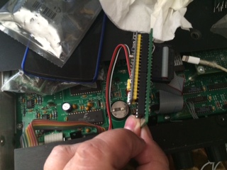
I measured, and the space is RIGHT!
thank you!
synthi
this is the current display
like this one 
I would be wildly surprised if any “Arduino display library mapped to the VFD commands.” That being said, I have worked with the OLED displays and their libraries are straight-forward.
Assuming that Arduino is the right platform (I think there are better solutions, more later), then there are two obvious ways to pull-off this translation: (very simplistic vuew, not fully baked)
– Bring in the parallel stream, decode instructions and data….
IF data, buffer the data character in SRAM, set a flag, return control to the state machine which will invoke the OLED library to update the OLED display.
IF instruction, decode and translate to 1 of more OLED library calls, set a flag, return control to the state machine which will call the OLED library to pricess the instruction(s).
– Bring in the parallel stream, decode.
IF character send to OLED library, loop.
IF instruction, send to OLED library, loop.
Both approaches have strength and weaknesses.
IMO, Arduino is not my 1st choice. I think FPGA is the most desirable if your design has volume. If your design is just 1-off for your personal use then maybe Arduino… but you’re in for a wild ride IMO.
Futaba sells a LCD emulator.
RU left-brain or right-brain … that is, are you up to the challenge? IMO, not a beginner project or even an intermediate project.
So, distilling if all, STM32duino & OLED may well fit your need. You will need to build the entire parallel logic interface both hsrdware and software. The OLED stuff is pretty well canned but I have no idea if the OLED library is optimized to be usable.
If you want to see OLED + STM32duino, I have some examples here: https://www.hackster.io/rayburne/projects
Ray
Thank you for your suggestions and your experiments with OLED
Will be one shot project… and yes I’m up for the challenge
and I switched from Arduino to STM just because of the missing ports on the Arduino platform
the space is important too: I have only 99mm x 34mm for the substitution
(protoboard + stm32f103 + oled + cabling)
just an idea
The DISPD0 to DISPD7 needs to be connected to PA0 to PA7
DISPBSY to PB6
DISPWRT to PB7
DISPRXD to GND
I need some example from people having done some parallel polling
thanks
Antonio
I need some example from people having done some parallel polling
thanks
Antonio
<https://github.com/sheepdoll/AVRVFDCLOCK.git>
This emulates a standard 14 pin LCD on a 14 segment alpha numeric VFD. I used the popular h44780 protocol so that it is drop in for any LCD. The protocol is basically a shift register.
A lot of the FUTABA vfd’s used this protocol. Others were basically a glass teletype display that used ASCII codes and escape sequences to position the cursor. I prefer the 14 pin version.
If I ever find that elusive thing called uninterrupted time I was working on connecting this to one of my STM32s.
I’m getting some result
I’ve attached an interrupt to the PB5 port on RISING (WRITE is HI)
the interrupt is
if the SELECT is LOW
setting BUSY HIGH
reading from the PA0 to PA7
setting BUSY LOW
but I’m getting very strange chars from the data read (invstigating)
uint8_t GetData()

{

uint8_t char_in =

(digitalRead(Data0) << 0) +

(digitalRead(Data1) << 1) +

(digitalRead(Data2) << 2) +

(digitalRead(Data3) << 3) +

(digitalRead(Data4) << 4) +

(digitalRead(Data5) << 5) +

(digitalRead(Data6) << 6) +

(digitalRead(Data7) << 7);
return char_in;
}
now the reading loop is this one
void interrupt()

{

if (!(GPIOB->regs->IDR & 0x0004)) // ignore if select signal is not present

{

//turn on the busy signal

GPIOB->regs->ODR |= 0b0001000000000000;
uint8_t data = GPIOA->regs->IDR & 0x00FF;
//process the new byte
processData(data);
delayMicroseconds(35);
GPIOB->regs->ODR &= ~(0b0001000000000000);
}
}
Some guys with the same problem got their lexicon to life again:
https://www.gearslutz.com/board/geekslu … oblem.html
the error is giving m is E4
that is “Display error”
In some way, the device knows I’m not using the original FUTABA
If I override the block, pressing UP and TEMPO, the reverb starts and works correctly
what I’m getting is some spurious character in the parallel port
for example I’m getting 0x30 when I’m expecting 0x20
but in other screen I’m getting the correctly 0x20 and 0x30 !
other thing:
one of the command for the FUTABA is “DP” (display position)
after DP there is always a byte between 0x00 and 0x27 (40 positions in the FUTABA)
but sometimes I’m getting wrong positions, like “252” or “168”
and is happening always in the same screens: I suspect there are some timing issues
OR the DATA port is not correctly cleaned after reading
thanks
madias wrote:Ok, for that nearly 500USD device (current used market price) it’s a good idea to investigate a little bit further:
Some guys with the same problem got their lexicon to life again:
https://www.gearslutz.com/board/geekslu … oblem.html
All in all this sounds like a job for:
http://www.aliexpress.com/item/1set-New … 33314.html
Beyond the analyzing things you can measure the real timing with it, maybe you are really a little bit off (but it’s strange that it happens in the particular screens.)
Display error: I would keep as a “childlock feature”.
If most of the remaining errors are reproduceable I would build as many exceptions in code as possible, because this code is only for this single device and not for mass productions.
solved the problem of spourious chars
I cleaned the port for every read
now the full callback for reading is
void interruptFunc()

{

//turn on the busy signal

GPIOB->regs->BSRR = 0b0000000000010000;
uint8_t data = GPIOA->regs->IDR & 0b0000000011111111;
//clean bits
GPIOA->regs->BRR = 0b0000000011111111;
//process the new byte
processData(data);
//delayMicroseconds(200);
GPIOB->regs->BRR = 0b0000000000010000;
}
It would be a shame dropping such a special sounding device because of a lousy display!
I hope that we will never see in the future Ebay “sellers” with a “Lexicon PCM80/81 Display upgrade kit for only 250USD” using your code (without credits).
Just one more thinking: Would a simple 2002LCD wouldn’t fit better into the lex? –> http://www.aliexpress.com/wholesale?cat … xt=lcd2002
so I decided, let’s learn something… ![]()
attached a little video where I’m using a i2c 0.96 bicolor oled (128 x 64) ($4.23 !!)
I did 2 different text size experiment (but the display is still TOO SMALL! like a quarter of dollar)
you can see the speed of changes
madias wrote:Congratulations synthi!
It would be a shame dropping such a special sounding device because of a lousy display!
I hope that we will never see in the future Ebay “sellers” with a “Lexicon PCM80/81 Display upgrade kit for only 250USD” using your code (without credits).
Just one more thinking: Would a simple 2002LCD wouldn’t fit better into the lex? –> http://www.aliexpress.com/wholesale?cat … xt=lcd2002
during the weekend I did a protoboard and I missed completely measures… ![]()
I forgot that the connector protruded for about 20 mm !
I need a female connector with 90 deg of rotation (parallel to the board)
currently I used velcro to maintain the screen in place
and the idea is to fix the (insulated) protoboard too with velcro, to the top panel
- IMG_5502.JPG (36.34 KiB) Viewed 1044 times
I’m attaching the PSEUDO schematics and the BIN file for and OLED 128×64 with I2C SH1106 controller (works on SSD1306 too, but I tested more on 1106)
the 2 switches in the scheme let you play with 4 different font configurations
OFF OFF 2 lines small << —– best ![]()
ON OFF 2 lines big 1 small
OFF ONN 1 small 2 big
ON ON 4 lines big
- FutabaEmulation.pdf
- (60.68 KiB) Downloaded 82 times
Thanks
All Comments