I set this all up on an Arduino UNO and it runs just fine. It’s a small program that uses the serial monitor for inputting commands to control the servos.
After I did this I tried using the same program on an STM32F103C8 board. The program runs just fine in terms of inputting and printing out the Servo commands. However, it doesn’t move the servos. I’m suspecting that it has something to do with the I2C not being set up properly.
On the UNO all I did was include the Wire.h library along with the Adafruit library for the 9685 board and everything works. But this doesn’t seem to work on the STM32 board.
Do I need to do something more to set up the I2C bus on the STM32 board? I’m using pins PB6 and PB7 for SCL and SDA respectively.
Here is the code. It includes a lot of Serial.print statements so I can see what’s happening on the serial monitor. That much is working just fine. But the servos aren’t responding on the STM32 system. But the program runs just fine on the Arduino UNO.
Here’s the code:
/*

PCA9685 PWM Servo Driver

My Version using Kayboard input and Serial COM.

using four servos

*/
// Include Wire Library for I2C Communications
#include <Wire.h>
// Include Adafruit PWM Library
#include <Adafruit_PWMServoDriver.h>
// Variables used for Serial monitor
String servo_position_string;
char sps_array[4];
int servo_position_integer;
String message = "Input R, L, or M for Right, Left, Middle Servo Position: (4 servos)";
bool serial_msg_flag = true;
// Variables for the PCA9685 board
#define MIN_PULSE_WIDTH 650
#define MAX_PULSE_WIDTH 2350
#define FREQUENCY 50
// The PCA9685 board address begins at 0x40,
Adafruit_PWMServoDriver pwm = Adafruit_PWMServoDriver(0x40);
// Serial input value
int servo_input_Val; // This will be my keyboard input value for the servo position.
// Define Motor Outputs on PCA9685 board
// int motorA = 0;
int motor_pointer = 0;
int pos_variable = 0;
// Begin SETUP
void setup()
{
// Set up to communicate via laptop USB connection.
Serial.begin(9600);
// Not much here all we do is begin the pwm Adafruit object and set the frequency to 50 Hz.
pwm.begin();
pwm.setPWMFreq(FREQUENCY);
}
void loop() {
if (serial_msg_flag)
{
Serial.println(message);
serial_msg_flag = false; // message has been printed.
}
while (Serial.available())
{
servo_position_string = Serial.readString(); // get the input string
Serial.println(servo_position_string); // print the input string
Serial.println(servo_position_string.length());
// ------------ test the input for correct values --------------
if (servo_position_string.length() > 0 && servo_position_string.length() < 7)
{
servo_position_string.toCharArray(sps_array, 5);
motor_pointer = 0;
Serial.print("Motor Pointer Before Loop = ");
for (int i=0; i<4; i++)
{
Serial.print(sps_array[i]);
//Serial.println("_");
}
Serial.println(motor_pointer);
for (int i=0; i <4; i++)
{
Serial.print("sps_array Character = ");
Serial.println(sps_array[i]);
// set the pos-variable to the correct value
if (sps_array[i] == 'R' || sps_array[i] == 'r') {pos_variable = 0;}
else if (sps_array[i] == 'M' || sps_array[i] == 'm') {pos_variable = 500;}
else if (sps_array[i] == 'L' || sps_array[i] == 'l') {pos_variable = 1000;}
else {pos_variable = 0;}
// print out results to the serial monitor
Serial.print("Motor_pointer = ");
Serial.println(motor_pointer);
Serial.print("pos_variable = ");
Serial.println(pos_variable);
// call the moveMotor routine for each servo
moveMotor (pos_variable, motor_pointer);
motor_pointer = motor_pointer + 4;
}
}
else
{
Serial.println("out of range error");
}
serial_msg_flag = true; // ok to print message again.
}
}
// This is the subroutine or Method named moveMotor
// it requires two integers
// controlIn is the analog input --- This comes from the serial input.
// motorOut is the servo pin number of the PCA9685 board.
void moveMotor(int potVal, int motorOut)
{
int pulse_wide, pulse_width;
pulse_wide = map(potVal, 0, 1023, MIN_PULSE_WIDTH, MAX_PULSE_WIDTH);
// the actual pulse_width is then caculated using the value of pulse-wide.
pulse_width = int(float(pulse_wide) / 1000000 * FREQUENCY * 4096);
//Send information to PC9684 Board via I2C
pwm.setPWM(motorOut, 0, pulse_width);
}
Can anyone give me some suggestions of what needs to be changed? I’ll post the library code below. One thing to note is that this also uses the Arduino Wire.h library the Adafruit servo library below clearly states that is points to an I2C “wire compatible” object. So I’m guessing that the STM32F103C8 is wire compatible? Does this mean it needs to be compatible with the Wire.h library?
In any case, here’s the Adafruit servo library code.
Adafruit_PWMServoDriver.h
/***************************************************

This is a library for our Adafruit 16-channel PWM & Servo driver
Pick one up today in the adafruit shop!
------> http://www.adafruit.com/products/815
These displays use I2C to communicate, 2 pins are required to
interface. For Arduino UNOs, thats SCL -> Analog 5, SDA -> Analog 4
Adafruit invests time and resources providing this open source code,
please support Adafruit and open-source hardware by purchasing
products from Adafruit!
Written by Limor Fried/Ladyada for Adafruit Industries.
BSD license, all text above must be included in any redistribution
****************************************************/
#ifndef _ADAFRUIT_PWMServoDriver_H
#define _ADAFRUIT_PWMServoDriver_H
#if ARDUINO >= 100
#include "Arduino.h"
#else
#include "WProgram.h"
#endif
#include "Wire.h"
#define PCA9685_SUBADR1 0x2
#define PCA9685_SUBADR2 0x3
#define PCA9685_SUBADR3 0x4
#define PCA9685_MODE1 0x0
#define PCA9685_PRESCALE 0xFE
#define LED0_ON_L 0x6
#define LED0_ON_H 0x7
#define LED0_OFF_L 0x8
#define LED0_OFF_H 0x9
#define ALLLED_ON_L 0xFA
#define ALLLED_ON_H 0xFB
#define ALLLED_OFF_L 0xFC
#define ALLLED_OFF_H 0xFD
/**************************************************************************/
/*!
@brief Class that stores state and functions for interacting with PCA9685 PWM chip
*/
/**************************************************************************/
class Adafruit_PWMServoDriver {
public:
Adafruit_PWMServoDriver(uint8_t addr = 0x40);
Adafruit_PWMServoDriver(TwoWire *I2C, uint8_t addr = 0x40);
void begin(void);
void reset(void);
void setPWMFreq(float freq);
void setPWM(uint8_t num, uint16_t on, uint16_t off);
void setPin(uint8_t num, uint16_t val, bool invert=false);
private:
uint8_t _i2caddr;
TwoWire *_i2c;
uint8_t read8(uint8_t addr);
void write8(uint8_t addr, uint8_t d);
};
#endif
How do you power the boards?
Do you have pull-up resistors for the I2C lines?
[stevestrong – Tue Sep 04, 2018 12:34 pm] –
Please post here the complete Arduino IDE message when you build and upload the project.
Here’s the Arduino IDE upload message:
Sketch uses 26084 bytes (39%) of program storage space. Maximum is 65536 bytes.

Global variables use 3712 bytes (18%) of dynamic memory, leaving 16768 bytes for local variables. Maximum is 20480 bytes.

stm32flash 0.4
http://stm32flash.googlecode.com/
Using Parser : Raw BINARY
Interface serial_w32: 115200 8E1
Version : 0x22
Option 1 : 0x00
Option 2 : 0x00
Device ID : 0x0410 (Medium-density)
- RAM : 20KiB (512b reserved by bootloader)
- Flash : 128KiB (sector size: 4x1024)
- Option RAM : 16b
- System RAM : 2KiB
Write to memory
Erasing memory
Wrote address 0x08000100 (0.98%)
Wrote address 0x08000200 (1.96%)
Wrote address 0x08000300 (2.94%)
Wrote address 0x08000400 (3.93%)
Wrote address 0x08000500 (4.91%)
Wrote address 0x08000600 (5.89%)
Wrote address 0x08000700 (6.87%)
Wrote address 0x08000800 (7.85%)
Wrote address 0x08000900 (8.83%)
Wrote address 0x08000a00 (9.81%)
Wrote address 0x08000b00 (10.80%)
Wrote address 0x08000c00 (11.78%)
Wrote address 0x08000d00 (12.76%)
Wrote address 0x08000e00 (13.74%)
Wrote address 0x08000f00 (14.72%)
Wrote address 0x08001000 (15.70%)
Wrote address 0x08001100 (16.68%)
Wrote address 0x08001200 (17.67%)
Wrote address 0x08001300 (18.65%)
Wrote address 0x08001400 (19.63%)
Wrote address 0x08001500 (20.61%)
Wrote address 0x08001600 (21.59%)
Wrote address 0x08001700 (22.57%)
Wrote address 0x08001800 (23.55%)
Wrote address 0x08001900 (24.54%)
Wrote address 0x08001a00 (25.52%)
Wrote address 0x08001b00 (26.50%)
Wrote address 0x08001c00 (27.48%)
Wrote address 0x08001d00 (28.46%)
Wrote address 0x08001e00 (29.44%)
Wrote address 0x08001f00 (30.42%)
Wrote address 0x08002000 (31.41%)
Wrote address 0x08002100 (32.39%)
Wrote address 0x08002200 (33.37%)
Wrote address 0x08002300 (34.35%)
Wrote address 0x08002400 (35.33%)
Wrote address 0x08002500 (36.31%)
Wrote address 0x08002600 (37.29%)
Wrote address 0x08002700 (38.28%)
Wrote address 0x08002800 (39.26%)
Wrote address 0x08002900 (40.24%)
Wrote address 0x08002a00 (41.22%)
Wrote address 0x08002b00 (42.20%)
Wrote address 0x08002c00 (43.18%)
Wrote address 0x08002d00 (44.17%)
Wrote address 0x08002e00 (45.15%)
Wrote address 0x08002f00 (46.13%)
Wrote address 0x08003000 (47.11%)
Wrote address 0x08003100 (48.09%)
Wrote address 0x08003200 (49.07%)
Wrote address 0x08003300 (50.05%)
Wrote address 0x08003400 (51.04%)
Wrote address 0x08003500 (52.02%)
Wrote address 0x08003600 (53.00%)
Wrote address 0x08003700 (53.98%)
Wrote address 0x08003800 (54.96%)
Wrote address 0x08003900 (55.94%)
Wrote address 0x08003a00 (56.92%)
Wrote address 0x08003b00 (57.91%)
Wrote address 0x08003c00 (58.89%)
Wrote address 0x08003d00 (59.87%)
Wrote address 0x08003e00 (60.85%)
Wrote address 0x08003f00 (61.83%)
Wrote address 0x08004000 (62.81%)
Wrote address 0x08004100 (63.79%)
Wrote address 0x08004200 (64.78%)
Wrote address 0x08004300 (65.76%)
Wrote address 0x08004400 (66.74%)
Wrote address 0x08004500 (67.72%)
Wrote address 0x08004600 (68.70%)
Wrote address 0x08004700 (69.68%)
Wrote address 0x08004800 (70.66%)
Wrote address 0x08004900 (71.65%)
Wrote address 0x08004a00 (72.63%)
Wrote address 0x08004b00 (73.61%)
Wrote address 0x08004c00 (74.59%)
Wrote address 0x08004d00 (75.57%)
Wrote address 0x08004e00 (76.55%)
Wrote address 0x08004f00 (77.53%)
Wrote address 0x08005000 (78.52%)
Wrote address 0x08005100 (79.50%)
Wrote address 0x08005200 (80.48%)
Wrote address 0x08005300 (81.46%)
Wrote address 0x08005400 (82.44%)
Wrote address 0x08005500 (83.42%)
Wrote address 0x08005600 (84.40%)
Wrote address 0x08005700 (85.39%)
Wrote address 0x08005800 (86.37%)
Wrote address 0x08005900 (87.35%)
Wrote address 0x08005a00 (88.33%)
Wrote address 0x08005b00 (89.31%)
Wrote address 0x08005c00 (90.29%)
Wrote address 0x08005d00 (91.27%)
Wrote address 0x08005e00 (92.26%)
Wrote address 0x08005f00 (93.24%)
Wrote address 0x08006000 (94.22%)
Wrote address 0x08006100 (95.20%)
Wrote address 0x08006200 (96.18%)
Wrote address 0x08006300 (97.16%)
Wrote address 0x08006400 (98.14%)
Wrote address 0x08006500 (99.13%)
Wrote address 0x080065e4 (100.00%) Done.
Starting execution at address 0x08000000... done.
I see that you are using the serial upload method. Which OS?
The pull-ups should be connected to 5V.
Try to connect PB6 or PB7 to PC13, this way the on-board LED should blink when there is some communication on the I2C bus.
This will check whether the I2C lines toggle or not.
[stevestrong – Tue Sep 04, 2018 7:01 pm] –
I was more interested on the build output (compiler lines), not on counting upload percentages…
I’m compiling this using Arduino IDE ver 1.8.5
The compiler only reports the following with no errors.
Sketch uses 26084 bytes (39%) of program storage space. Maximum is 65536 bytes.
Global variables use 3712 bytes (18%) of dynamic memory, leaving 16768 bytes for local variables. Maximum is 20480 bytes.
[stevestrong – Tue Sep 04, 2018 7:01 pm] –
I see that you are using the serial upload method. Which OS?
I’m using a Windows 10 Notebook computer. And keep in mind that this has all been working for the UNO and MEGA boards. I’ve also been using the STM32f103C8 successfully for other projects as well. I haven’t had a problem until now when trying to use the I2C.
[stevestrong – Tue Sep 04, 2018 7:01 pm] –
The pull-ups should be connected to 5V.
That’s my current configuration.
[stevestrong – Tue Sep 04, 2018 7:01 pm] –
Try to connect PB6 or PB7 to PC13, this way the on-board LED should blink when there is some communication on the I2C bus.
This will check whether the I2C lines toggle or not.
Yes, I just now tried that and the PC13 does indeed blink on both the SCL and SDA lines when I send that servo control data.
Thanks for that tip, I would have never thought of that.
But let’s try not to lose sight of the fact that even Adafruit suggested that I might need to modify their open-source library and that it’s currently not programmed for the STM32F103C8.
I was also wondering whether the Arduino Wire.h library might need to be modified instead? Because the Adafruit library actually uses #include Wire.h.
Currently I’m not sure where to find the Wire.h and Wire.cpp files. I’ll have to do a search for them. I would like to see what’s in those files as well.
Finally, I have a another “guess” as to what might be wrong. The Arduino board runs at a much lower frequency than the STM32 board. So I’m wondering if the problem might be in the I2C frequency that is being used? I’m not sure how or where to change that. I’m new to I2C, so I don’t have any experience with how to program it in the details.
But yeah, the I2C lines are blinking when I connect them to the PC13 LED. So apparently it’s sending data over the lines. Could it just be that it’s being sent at the wrong frequency?
I don’t have a scope. I wish I did.
Here’s a photo of my set up. I tried to explain some of the wiring using PCpaint. I don’t currently have a full schematic of my set up. I’m planning on drawing one up as I would like to eventually make a YouTube video of how to set this up. But right now I’m still trying to get it work.
The PCA9685 board is also powered by the 5 volt breadboard rail. The the ground of the two rails are tied together. The STM32 is obviously powered by the 3.3 v rail. And of course the STM32 is running the program because the it’s returning all the proper information on the serial terminal.
I didn’t call it out in the photo but there is a small red board between the breadboard power supply module and the STM32. That is the USB to Serial board. That connects to pins PA9 and PA10 of the STM32. And that serial connection is obviously working just fine since I can upload programming to the STM32 and then see the Serial data being printed back to me.
So the problem appears to be with getting that data to the PCA9685 board correctly. And the trick of tying PB6 and PB7 to the PC13 LED worked to show that at least something is happening on the SCL and SDA lines when I tell the servos to move.
So the problem seems to be related exclusively to an I2C problem somehow.
Could it a frequency issue?
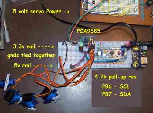
- STM32-servo-sm.jpg (22.81 KiB) Viewed 741 times
I have only little use of Ardunio but have used blue pill on ardunio a little bit but more used it with generic C
STM32f103C8 pinout:
I2C1_SDA = PB7
I2C1_SCL = PB6
I2C2_SDA = PB11
I2C2_SCL = PB10
I have used the PCA9685 quite a lot on a number of different projects in a number of different platforms but all platforms(RPi, ESP8266, ESP32, STM32) have been a 3.3v systems. I always have powered the PCA9685 on 3.3v as this is within the specs in datasheet. Powering the PCA9685 on 3.3v means the data lines will be the same as Vcc, in the spec data lines r suppose to be within 0.7 of Vcc so 3.3v is slightly outside of specs but I do doubt this is what’s causing your problem.
I haven’t used Ardunio I2C library so not sure how it works but have used I2C with STM32 in C and have just used the internal pull-ups on the MCU without adding any extra external pull-ups at all. I must admit I didn’t write my own library for hardware I2C on STM32 but just used the HAL library provided by ST as the HAL library worked for me first attempt.
First 2 things to try
1. just power PCA9685 on 3.3v
2. remove your external pull-ups then write a sketch that say delay 3 seconds then just setups the I2C then does nothing but go around in a loop. Then measure the voltage on the I2C pins during start up if they are basically close to 0 during startup but then go to 3.3v after 3 seconds when the I2C is setup this tells you that the internal pull-ups are being engaged when the Ardunio library is setting up the I2C and you won’t need the external pull-ups
[flyboy74 – Thu Sep 06, 2018 2:05 am] –
1. just power PCA9685 on 3.3v2. remove your external pull-ups then write a sketch that say delay 3 seconds then just setups the I2C then does nothing but go around in a loop. Then measure the voltage on the I2C pins during start up if they are basically close to 0 during startup but then go to 3.3v after 3 seconds when the I2C is setup this tells you that the internal pull-ups are being engaged when the Ardunio library is setting up the I2C and you won’t need the external pull-ups
That actually was my original set up. I originally powered the PCA9685 using 3.3v, because according to the spec sheet it’s supposed to run on anything from 3 to 5 volts. So I figured that running it on 3.3v might be a better idea since the STM32 is a 3.3v MCU. I tried that method both without pull-ups, and then later again with pull-ups. I couldn’t get it to work using 3.3v either. That’s when I moved up to using 5v for the PCA9685 but still no go.
I’m still suspecting a problem with the PCA9685 library since Adafruit suggested that their library may need to be modified for this MCU. But I have no clue how to modify it. If I need to learn how to modify that library I imagine it’s going to take me quite a while to learn how to do that. Especially since I’m not working on this project full-time.
I’m determined to get this to work. Surely there must be a way. I’m kind of surprised that there isn’t any information available on how to use this “Blue Pill” with the PCA9685 board. I did see a video on how to use a GY521 module with this “Blue Pill” board. That also uses I2C. I have some GY521 modules here. So since I have that video instruction I can try that board first. This problem might be unique to the PCA9685 Library.
I was hoping I could post here and get a quick fix. ![]()
But I guess I’ll have to resort to the old-fashioned way of just taking a lot of time to learn more by trying some other I2C projects first.
If I ever get this working I’ll come back and post the solution. My current guess is that the Adafruit Library needs to be modified in some way for the STM32F103C8 MCU. I just don’t yet know how to do that.
By the way I also have some “Black Pill” boards here. They too are STM32F103C8. I haven’t been able to get them to work with the PCA9685 either. After I find the solution it will probably work for both of these STM32 boards.
~~~~~
Note: I’m only just starting with the STM32. I needed to move to a smaller overall board so I can fit it inside G-Scale trains that I’m going to set up to be computer controlled. I’m determined to learn these MCU’s inside and out. So it’s just a matter of time. And when I do that, I also hope to make some YouTube videos to share what I’ve learned.
It was the STM32F407 that I was using I2C on and didn’t need external pull-ups but looking at the manual for the STM32F103 it looks like it will need external pull-ups
This from the manual of the STM32F103
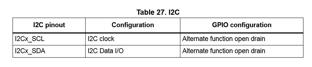
- i2c.JPG (40.38 KiB) Viewed 358 times
Here the the libiary https://github.com/OutOfTheBots/ESP32_P … PCA9685.py that I wrote. As you can see it is not a lot of code, it is written in Micro-Python so will need to be ported to Ardunio STM32 but with looking at this code and reading the data sheet it shouldn’t be too hard to nut out.
It is the library that I used for servo control on this robot https://www.youtube.com/watch?v=-MyodFHwfTU and this robot https://www.youtube.com/watch?v=9fHB7VB73dg
[flyboy74 – Thu Sep 06, 2018 3:19 am] –
To write your own library to operate a PCA9685 is quite simple.Here the the libiary https://github.com/OutOfTheBots/ESP32_P … PCA9685.py that I wrote. As you can see it is not a lot of code, it is written in Micro-Python so will need to be ported to Ardunio STM32 but with looking at this code and reading the data sheet it shouldn’t be too hard to nut out.
It is the library that I used for servo control on this robot https://www.youtube.com/watch?v=-MyodFHwfTU and this robot https://www.youtube.com/watch?v=9fHB7VB73dg
Thanks for sharing you library code. I’m familiar with Python so your code is easy for me to read. I’ll need to figure out how to convert this into something the Arduino IDE can use. But it looks simple enough. I would prefer to write my own library eventually anyway. So this will be a good learning experience for me. I like to keep libraries really simple. Often times libraries include a lot of extra code for devices I’ll never use. So it’s nice to be able to slim them down to only what I need.
But you can also try the followings:
1. run the I2C scanner sketch – to see whether your board (I2C device) is detected at all
2. replace TwoWire by SoftWire (use software I2C instead of the hardware).
There were issues with the symptom that software I2C worked but the HW I2C not. One of them was solved here: https://github.com/rogerclarkmelbourne/ … 2/pull/508
[stevestrong – Thu Sep 06, 2018 8:30 am] –
The easiest way to identify the problem would be to compare the I2C signals when using UNO to that when using STM32F1.But you can also try the followings:
1. run the I2C scanner sketch – to see whether your board (I2C device) is detected at all
Thanks Steve! I didn’t even know there was an I2C scanner sketch. It’s in my toolbox now!
The scanner reports:
Scanning…
I2C device found at address 0x40 !
I2C device found at address 0x70 !
done
I only have the one I2C device connected, and I have it called out as 0x40. I don’t know what the 0x70 address is all about? Maybe I should try calling out the address in my sketch as 0x70 and see if that helps.
But at least it’s recognizing the PCA9685 board is connected. That’s nice to know.
[stevestrong – Thu Sep 06, 2018 8:30 am] –
2. replace TwoWire by SoftWire (use software I2C instead of the hardware).
There were issues with the symptom that software I2C worked but the HW I2C not. One of them was solved here: https://github.com/rogerclarkmelbourne/ … 2/pull/508
I look into your SoftWire suggestion. Maybe that will work.
This board/chip uses I2C 7-bit address between 0x40-0x7F, selectable with jumpers.
Are you sure your address configuration is OK?
It is weird that the chip replies on two different addresses.
You should definitely try the software I2C version (first the scanner).
I2C device found at address 0x40 !
I2C device found at address 0x70 !
This is normal with PCA9685, it always replies to a scan on both 0X40 (or selected address with jumpers) and 0x70, just use 0x40
Ok, I’ll be branded as the world’s biggest idiot from this day forward.
Apparently when using the STM32 CPU I need to use uint16_t for all my integers instead of just plain int.
Using just plain “int” for numbers works just fine on the Arduino UNO. But for some reason the STM32 needs to have all numbers called out as unsigned 16 bit integers.
So that was it.
It’s working just fine now.
Apparently the Adafruit library works alright with the STM32F103C8 too.
Just got to make sure to use uint16_t values instead of just plain int.
Man, that took me a couple of weeks to discover this. But I do have the excuse that just plain int works just fine on the UNO. So who would have guessed that it won’t work on the STM32?
[Robo_Pi – Fri Sep 07, 2018 2:30 am] –
Man, that took me a couple of weeks to discover this. But I do have the excuse that just plain int works just fine on the UNO. So who would have guessed that it won’t work on the STM32?
This issue was caused this time by a bad coding technique.
Since”int” has different sizes on different architectures, it is always recommended to use int8/int16/int32 in a code which is designed to run on several architectures.
This should be a good lesson, for all of us.
[stevestrong – Fri Sep 07, 2018 7:31 am] –
This should be a good lesson, for all of us.
Yes, this certainly is a valuable lesson to learn for me. I would like my code to be as portable as possible at least between the UNO, Mega, Blue pill, and Black pill since these are the MCU’s I’m currently designing around. Of course, due to the difference in pin numbers and their functions it’s not always possible to write code that it is totally portable without at least some pin number changes. Still it’s nice to have the code as portable as possible.
My original code was modified from a YouTube channel example using the PCA9685 servo controller and an Arduino Uno. It’s a really nice YouTube channel called “DroneBot Workshop“. I really like the attention he gives to the details in his videos. But he was using “int” in his sketches which obviously works just fine on the UNO. I’ll have to send him an email and tell him about this because I’m sure he would like to know. He’s a stickler for details. In fact, he usually points things like this out. Apparently he’s not aware of this either. I’m sure he would have mentioned it if he was. He typically offers tips like using different pin numbers on different devices, but he didn’t mention the need to call out more precise integer values for different MCUs. I’ll send him an email, I’m sure he’ll appreciate the information.
By the way, here’s a link to the specific video where he describes how to use the PCA9685 servo controller. In his example he is using 4 sliding potentiometers connected to the Analog Input pins of the UNO, and using that to control a “Me Arm”. Just beware that to use this on an STM32 you need to change int to uint16_t. This is a really well-done video. I really like the detail this man goes into in his videos.
If anyone is still reading this thread I have an additional question.
Now that I got I2C1 working on pins PB6, PB7 I’d like to see if I can also get this to work on I2C2 on pins PB10, PB11.
What do I need to do to specific this second I2C line?
As far as I’m aware I didn’t do anything to tell it to use I2C1 or PB6, PB6. So I’m guessing I2C1 is a default?
How to I tell it to use the second I2C lines?
2. declare outside of any function:
TwoWire Wire2(2); // instead of HardWire Wire2(2);
C:\Users\James\Documents\Arduino\libraries\Adafruit_PWM_Servo_Driver_Library\Adafruit_PWMServoDriver.cpp:32:1: error: ‘HardWire’ does not name a type
HardWire Wire2(2);
^
C:\Users\James\Documents\Arduino\libraries\Adafruit_PWM_Servo_Driver_Library\Adafruit_PWMServoDriver.cpp: In constructor ‘Adafruit_PWMServoDriver::Adafruit_PWMServoDriver(uint8_t)’:
C:\Users\James\Documents\Arduino\libraries\Adafruit_PWM_Servo_Driver_Library\Adafruit_PWMServoDriver.cpp:40:11: error: ‘Wire2’ was not declared in this scope
_i2c = &Wire2;
^
Multiple libraries were found for “Wire.h”
Used: C:\Program Files (x86)\Arduino\hardware\Arduino_STM32-master\STM32F1\libraries\Wire
Not used: C:\Program Files (x86)\Arduino\hardware\Arduino_STM32-master\STM32F1\libraries\WireSlave
exit status 1
Error compiling for board Generic STM32F103C series.
TwoWire Wire2(2);[stevestrong – Sat Sep 08, 2018 12:43 am] –
sorry, it should be
TwoWire Wire2(2);
[stevestrong – Fri Sep 07, 2018 7:31 am] –
This issue was caused this time by a bad coding technique.
Since”int” has different sizes on different architectures, it is always recommended to use int8/int16/int32 in a code which is designed to run on several architectures.
Agreed. I have to add this of my list of gripes with the typical Arduino library. Specify your bit-width, please.
![[SOLVED] Discovery STM32F100RB — Trouble with timers and library structure](https://sparklogic.ru/wp-content/uploads/2019/11/st-stm32vl-discovery-90x90.jpg)
