for those who don’t have STLINK do like to download vs USB STM DFU mode
first setup the Black F407VET6 set the jumper from PA0 to BOOT0

Hold the K_UP button and plug the USB cable to PC.
(Due to the design, Hold the K_UP button and press the RESET will not enter to STM DFU mode)
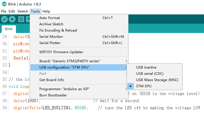
Select Arduino tools to STM DFU and press upload button.
When upload is completed MCU will auto reset and run the code.
and you will see the Upgrade successful !

continue …… how to setup the STM dfu in Arduino
https://hackaday.io/project/4139-stm32- … -converter
create a directory in <user>\Documents\Arduino\hardware\Arduino_STM32-master\tools\win\stfdu
unzip to “stfdu” directory
modify the platform.txt in Arduino\hardware\Arduino_STM32-master\STM32F4
change the compiler from binary to ihex , because the upload tools required.
compiler.elf2hex.flags=-O ihex

compiler.elf2hex.cmd=arm-none-eabi-objcopy
[poiuycat – Fri Oct 06, 2017 9:35 am] –
PS: I wonder how do I make USB serial work in DFU download.
You have to add -DSERIAL_USB to the cpu_flags in “boards.txt”:
generic_f407v.menu.usb_cfg.usb_dfu.build.cpu_flags=-DSERIAL_USB
[stevestrong – Fri Oct 06, 2017 12:06 pm] –
You have to add -DSERIAL_USB to the cpu_flags in “boards.txt”:
generic_f407v.menu.usb_cfg.usb_dfu.build.cpu_flags=-DSERIAL_USB
[poiuycat – Fri Oct 06, 2017 12:27 pm] –
I did try before adding -DSERIAL_USB in cpu_flags but it wont compile at all !!
Please post here the complete build output, including any error/warning message.
[stevestrong – Fri Oct 06, 2017 1:18 pm] –[poiuycat – Fri Oct 06, 2017 12:27 pm] –
I did try before adding -DSERIAL_USB in cpu_flags but it wont compile at all !!Please post here the complete build output, including any error/warning message.
this is the complete build output with out any error.
- DSERIAL_USB.txt
- (81.77 KiB) Downloaded 256 times
And I expect that you show us why it does not compile at all, show us the error messages.
Or do you mean that USB serial will not work?
[poiuycat – Fri Oct 06, 2017 1:31 pm] –[stevestrong – Fri Oct 06, 2017 1:18 pm] –[poiuycat – Fri Oct 06, 2017 12:27 pm] –
I did try before adding -DSERIAL_USB in cpu_flags but it wont compile at all !!Please post here the complete build output, including any error/warning message.
this is the complete build output with out any error.
DSERIAL_USB.txt
I found something strange !!
if I comment out
//Serial.begin(115200);
//Serial.println(“OK!!!!!!!!!!”);
complete build will fine and STM serial came out
if I use SerialUSB or Serial complete build OK but not working
SerialUSB.begin(115200);
SerialUSB.println(“OK!!!!!!!!!!”);
- SerialUSB not working.txt
- (81.77 KiB) Downloaded 217 times
void setup() {

delay(1000); // seems to be needed

Serial.begin(115200);

Serial.println("bla-bla");

...

}after few round of test and yes it work on you repo but not work on Roger’s repo
thanks again. ![]()
I thing is because of the usb serial buffer full or what … is this a bug or normal ? how do I check the usb buffer is full when that is unable to send out the data ? because normally HW serial system wont care the user is received the data or not but USB ?
byte LED_BUILTIN2 = PA7;

byte LED_BUILTIN1 = PA6;

// the setup function runs once when you press reset or power the board

void setup() {

//setupUSB();

// initialize digital pin LED_BUILTIN as an output.

//delay(3000);

SerialUSB.begin(115200);

//delay(3000);

SerialUSB.println("OK!!");
pinMode(LED_BUILTIN1, OUTPUT);
pinMode(LED_BUILTIN2, OUTPUT);
}
// the loop function runs over and over again forever
void loop() {
digitalWrite(LED_BUILTIN2, HIGH); // turn the LED on (HIGH is the voltage level)
SerialUSB.println("OK!!");
delay(100); // wait for a second
digitalWrite(LED_BUILTIN1, HIGH); // turn the LED off by making the voltage LOW
SerialUSB.println("OK!!");
delay(100); // wait for a second
digitalWrite(LED_BUILTIN2, LOW); // turn the LED on (HIGH is the voltage level)
SerialUSB.println("OK!!");
delay(100); // wait for a second
digitalWrite(LED_BUILTIN1, LOW); // turn the LED off by making the voltage LOW
delay(100); // wait for a second
}
I am new to the forum and interested in this thread because I would like to do a similar thing with another F4 board (see my STM32F407VGT6 postings). Ideally, I want to make it as “plug and play” as any Arduino board with a USB interface: i.e. I would like to upload the program over USB, then open a serial channel to the host for diagnostic output to the Arduino serial monitor window.
I work on Mac OSX with latest versions of the OS, Arduino IDE, and Roger Clark’s board definitions.
- My first question goes back to what happens before the start of the instructions at the start of the thread. I have installed dfu-util and can run it from Terminal.app, but I do not see “STM DFU” as an upload option in the IDE. Is there another step required to link the DFU utility into the IDE? Do I need an additional program such as DFU-Programmer / DfuSe?
- As I am not familiar with the board you are using, can you explain the significance of connecting PA0 to BOOT0?
- … and what does the “K_UP” button do?
Cheers,
Andy
In order to put STM32 in DFU moe you have to set BOOT1 to high. This is done over PA0.
K_UP is the button which is connected to PA0/W_UP: http://wiki.stm32duino.com/images/5/5c/ … EMATIC.PDF.
So if you press K_UP, this will keep the chip in DFU mode after reset.
“My” board is different in that BOOT0 and BOOT1 are pulled up by default. Jumpers are used to pull them down when needed. As I understand it, we don’t need to do anything with PA0 as the board internal power regulator will be on anyway (BYPASS_REG is not available on the F407V — i.e. 100-pin — packages). So I guess I can just run the DFU procedure with a jumper on BOOT1 to pull it down and set the mode to “boot from system memory”; then switch the jumper to BOOT0 to set the mode to “boot from flash memory” — which is the same procedure for any loading method.
Thanks for the clarification.
Andy