Looking for a simple way to tell compiler/linker to place the code and run it from an address in external SRAM.
For example I’ve got 512kB free space from 0x68000000 (the 103ZET6), and 64kB internally.
The execution from the external sram will be slower, however the size creates interesting opportunities.
The internal sram could still be used for vectors/stack and fast buffers.
The option would be to place specific functions into the external sram.
If our core and C experts know how and may provide a hint I am ready to elaborate.
Running code from SRAM in GNU GCC..
First of all, you need the –mlong-calls switch specified to the compiler. This is needed as calling functions in flash from sram or vice-versa require a branch instruction that can branch “further away”. Then you need the following in an accessible header file or at the top of a C file that will use it
#define RAMFUNC __attribute__ ((long_call, section (“.ramfunctions”)))
This is a macro for a function attribute which you can apply to a function that you want in SRAM. It really just places the function in a section called “.ramfunctions”, where it would be placed in a section called “.text” by default. (We need to update the linker script in a later step to tell the linker what to do with .ramfunctions). You can apply this to specific functions like shown below. (You have to apply it to the prototype as well).
RAMFUNC void MyRAMFunc(unsigned uiNumsamples) ;
RAMFUNC void MyRAMFunc(unsigned uiNumsamples) {
// Function Body
}
That works for C functions, you need to put something like this at the top of assembler functions (again putting the code into an appropriately named sections).
.section “.ramfunctions”
.align 8
.global PutOneChar
.thumb
.thumb_func
.type PutOneChar, %function
Then in the linker script file (*.ld) you need something like the line in red below inserted to tell the linker to put the functions marked as .ramfunctions into SRAM.
.data : AT (_etext)
{
_data = .;
*(vtable vtable.*)
*(.data .data.*)
*(.gnu.linkonce.d*)
. = ALIGN(4);
*(.ramfunctions) /* !!!! Placing functions in .ramfunctions section in RAM */
_edata = . ;
} > SRAM
This will store the function in flash to begin with, then copy it automatically into SRAM before it gets executed (almost identical to how initialised variables are handled). Just place RAMFUNC on any function that you want in RAM. Bear in mind that the attribute should be applied to any function that this function calls as well.
But where the code should come from? From flash? If it already fits in flash, then you could just run it from there, it would be faster, too.
On the other side, more meaningful, it would be nice to load code selectively form SD card and let it run from SRAM. But then you should somehow first bring the code parts onto SD card…
So as the first step we have to get text+data+bss into the external sram.
200000b8 <___ZN7print_tI16serial_default_tILm9600ELm72000000E8GPIO_PINILm1ELm9EES1_ILm0ELm65535EEEE5_putsEPKh.isra.4_veneer>:

200000b8:       f85f f000       ldr.w   pc, [pc]        ; 200000bc <___ZN7print_tI16serial_default_tILm9600ELm72000000E8GPIO_PINILm1ELm9EES1_ILm0ELm65535EEEE5_putsEPKh.isra.4_veneer+0x4>

200000bc: 08000277 .word 0x08000277The rd/wr with a 10ns sram could be 6/4cycles for the 103ZET6, or something like that.
http://www.st.com/content/ccc/resource/ … 200423.pdf
But the speed is not the critical factor here. The chance to run off the external sram is the main motivation.
Only the array has been placed to the external SRAM (10ns 256kx16) so far. Array accessed via pointers, not in Heap.
Internal SRAM:
Generating 30000 16bit uints:

BubbleSorting 30000 16bit uints:

Elapsed: 147182682  usecs

Sorted last 100 in ascending order:

29900 65270

29901 65271

29902 65274

29903 65281

29904 65282

29905 65287

29906 65288

..

29994 65516

29995 65518

29996 65519

29997 65523

29998 65528

29999 65533
BubbleSorting 30000 8bit uints:

Elapsed: 241123281  usecs
BubbleSorting 30000 16bit uints:
Elapsed: 275602656 usecs
BubbleSorting 30000 32bit uints:
Elapsed: 323401444 usecs
Here are some results while running standard Bubblesort on a set of 3000 generated random uints for various uints sizes.
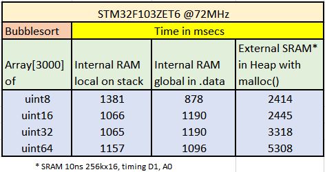
- Bubblesort_1.JPG (37.78 KiB) Viewed 14916 times
The way it worked was by having a separate linker script that uses whatever address you want to run from (I dont remember where FSMC seats in the memory map, but whatever address that is).
When using that linker script, it did not compile anything to use flash addresses, all went to RAM addresses, so you didn’t have to make anything different in your code, all was done by the linker for every piece of code, constants, etc. Obviosly someone had to copy all that to RAM before running, but that was done by the original bootloader with a certain upload option.
Then when uploading the sketch to the maple board, the bootloader would be the one that would copy that code to RAM, starting in the address in which the linker was set to, and finally call the entry point.
The bootloader was already in the board, the linker doesn’t even know about it, and the binary generated does not include any routine to copy the program from flash to RAM. It links exactly the same as if it was going to run from Flash, but it is using the address for RAM. You will understand if better if you download that linker script and check it out.
I did some tests myself on running from normal RAM, but with a custom bootloader that would first write the sketch to flash, then copy it to RAM, and run it. If the board was rebooted, it would copy the sketch to RAM again and run it, so I didn’t have to upload every single time, as it was the case with leaflabs run from RAM option. I did that when doing some speed tests running from RAM and wanted to avoid having to upload upon a reset.
I would do the same for your case, except that given the size, I agree is better to use an sdcard to store the code. So you could:
1.- Write a sketch to run from flash that initializes the FSMC, and then access an sdcard and reads whatever file you want, copies it to RAM, and then call the entry point. This should be easy to do.
2.- Create a new board variant, that uses a modified linker script that links the executable code to the bottom of FSMC address. The bin file generated can be copied to an SDCard, and loaded and executed by the program described in point 1.
You can also modify that same linker script to place the stack at the top of the external RAM address, since at the point that code is called to run, the FSMC is already initialized, but may be faster to keep the stack in internal memory for speed.
3.- Make sure the code generated in point 2 does not someway disable FSMC, changes the function of a pin used for FSMC, or anything like that.
This was the maple linker script for RAM, called ram.ld:
/*

* libmaple linker script for RAM builds.

*

* A Flash build puts .text, .rodata, and .data/.bss/heap (of course)

* in SRAM, but offsets the sections by enough space to store the

* Maple bootloader, which uses low memory.

*/
/*
* This pulls in the appropriate MEMORY declaration from the right
* subdirectory of stm32/mem/ (the environment must call ld with the
* right include directory flags to make this happen). Boards can also
* use this file to use any of libmaple's memory-related hooks (like
* where the heap should live).
*/
INCLUDE mem-ram.inc
/* Provide memory region aliases for common.inc */
REGION_ALIAS("REGION_TEXT", ram);
REGION_ALIAS("REGION_DATA", ram);
REGION_ALIAS("REGION_BSS", ram);
REGION_ALIAS("REGION_RODATA", ram);
/* Let common.inc handle the real work. */
INCLUDE common.inc
My first step was to make the FSMC alive and double check it works – it has been done.
The FSMC on that 103ZET6 wiki board works such it makes the exRAM bank3 = 0x68000000 to 0x68080000 (256kx16) transparent to the ARM.
My second step has been to start moving stuff into the exRAM – the easiest step has been with Heap. It does not need the FSMC be initialized before C starts so I still do it in setup(). Thus my Heap is now 0x68000000 to 0x6807FFF8. And it works.
Now – I would start to experiment with the older bootloader to compile for RAM, but the FSMC must be initiated in the crt0.s or somewhere like that.
I’ve found some hints already – it is described in STM examples for FSMC, but not sure we use the same crt0 mechanism here.
So the next step is to put the FSMC init into the C startup files.
  *         Called in startup_stm32f10x_xx.s/.c before jump to main.

* 	      This function configures the external SRAM mounted on STM3210E-EVAL

*         board (STM32 High density devices). This SRAM will be used as program

*         data memory (including heap and stack).
  *         Called in startup_stm32f10x_xx.s/.c before jump to main.

* 	      This function configures the external SRAM mounted on STM3210E-EVAL

*         board (STM32 High density devices). This SRAM will be used as program

*         data memory (including heap and stack).
Now the exercise is about to “enable the FSMC” inside the “system init” (where actually??), such we have FSMC alive and transparent before “something wants to mess” with the exRAM.. Ie., to copy initialized data from flash into exRAM during init or something like that
The actual sequence for BANK1_NE3 (0x68000000-..) is:
  RCC->AHBENR = 0x00000114;

RCC->APB2ENR = 0x000001E0;

GPIOD->CRL = 0x44BB44BB;

GPIOD->CRH = 0xBBBBBBBB;

GPIOE->CRL = 0xB44444BB;

GPIOE->CRH = 0xBBBBBBBB;

GPIOF->CRL = 0x44BBBBBB;

GPIOF->CRH = 0xBBBB4444;

GPIOG->CRL = 0x44BBBBBB;

GPIOG->CRH = 0x44444B44;

FSMC_Bank1->BTCR[4] = 0x00001011;

FSMC_Bank1->BTCR[5] = 0x00000200;
void init(void) {

setup_flash();

setup_clocks();

setup_nvic();

systick_init(SYSTICK_RELOAD_VAL);

wirish::priv::board_setup_gpio();

setup_adcs();

setup_timers();

wirish::priv::board_setup_usb();

wirish::priv::series_init();

boardInit();

setup_fsmc();  // <<<

}1.- Write a sketch to run from flash that initializes the FSMC, and then access an sdcard and reads whatever file you want, copies it to RAM, and then call the entry point. This should be easy to do.
2.- Create a new board variant, that uses a modified linker script that links the executable code to the bottom of FSMC address. The bin file generated can be copied to an SDCard, and loaded and executed by the program described in point 1.
You can also modify that same linker script to place the stack at the top of the external RAM address, since at the point that code is called to run, the FSMC is already initialized, but may be faster to keep the stack in internal memory for speed.
3.- Make sure the code generated in point 2 does not someway disable FSMC, changes the function of a pin used for FSMC, or anything like that.
..
oh heady days
srp
1. I built the bubblesort example with modified linker file – all sections placed in EXRAM from 0x68000000.
The .map file shows it is placed in the EXRAM (text, data, bss, heap, stack..)
The start_c.c includes the FSMC initialization, but as described above – FSMC is initialized just before jump to main – that may cause problems when running out of EXRAM, as before the FSMC initialization there is an exercise with copying inside the ram segment running in start_c.c .. ![]()
![]()
2. I converted the resulting bubbsort.bin file into a C-include-array which will be included via bubblesort.h into the sketch:
static unsigned char bubbsort[] = {

0x00, 0x00, 0x08, 0x68, 0xbd, 0x08, 0x00, 0x68, 0x11, 0x0c, 0x00, 0x68,

0x15, 0x0c, 0x00, 0x68, 0x19, 0x0c, 0x00, 0x68, 0x1d, 0x0c, 0x00, 0x68,

..

0x02, 0x00, 0x01, 0x04, 0x03, 0x09, 0x04, 0x00, 0x43, 0x00, 0x00, 0x00,

0x10, 0x48, 0x00, 0x68, 0xb8, 0x42, 0x00, 0x68

};

unsigned int bubbsort_len = 23132;
void branch_to_sram()

{

asm("bl   sram_start8;")
}
  Serial.println("Starting the .bin:");

asm("bl   sram_start8;");

or

asm("bl sram_start8\n\t"); asm( "r sram_start8";)I do not remember how was it, but it works fine for both internal RAM and internal Flash, so I am sure it will work the same for an address in exRAM.
EDIT:
Here is how it does it in main, when it is going to run the sketch in flash:
jumpToUser(USER_CODE_FLASH);
So we need a workaround.
The board is: http://wiki.stm32duino.com/index.php?ti … 32F103ZET6
and you need a 256kx16 or 512kx16 10-55ns SRAM, tsop44_2, 3.3V(!) (a lot of various types available).
The board works fine, $12. The SRAM I use is AS7C34098A-10TCN $3.50
So first 4 bytes, stack address, next 4 bytes, address of the initialization code
The first bytes of the .bin start:
  0x00, 0x00, 0x08, 0x68, 0xc9, 0x01, 0x00, 0x68, 0x31, 0x05, 0x00, 0x68,

0x35, 0x05, 0x00, 0x68, 0x39, 0x05, 0x00, 0x68, 0x3d, 0x05, 0x00, 0x68,

0x41, 0x05, 0x00, 0x68, 0x91, 0x05, 0x00, 0x68, 0x91, 0x05, 0x00, 0x68,

0x91, 0x05, 0x00, 0x68, 0x91, 0x05, 0x00, 0x68, 0x91, 0x05, 0x00, 0x68,

0x91, 0x05, 0x00, 0x68, 0x91, 0x05, 0x00, 0x68, 0x91, 0x05, 0x00, 0x68,

0xfd, 0x08, 0x00, 0x68, 0x91, 0x05, 0x00, 0x68, 0x91, 0x05, 0x00, 0x68,

0x91, 0x05, 0x00, 0x68, 0x91, 0x05, 0x00, 0x68, 0x91, 0x05, 0x00, 0x68,

0x91, 0x05, 0x00, 0x68, 0x91, 0x05, 0x00, 0x68, 0x91, 0x05, 0x00, 0x68,

0x91, 0x05, 0x00, 0x68, 0x91, 0x05, 0x00, 0x68, 0x91, 0x05, 0x00, 0x68,

0x91, 0x05, 0x00, 0x68, 0x91, 0x05, 0x00, 0x68, 0x91, 0x05, 0x00, 0x68,

0x91, 0x05, 0x00, 0x68, 0x91, 0x05, 0x00, 0x68, 0x91, 0x05, 0x00, 0x68,

0x91, 0x05, 0x00, 0x68, 0x91, 0x05, 0x00, 0x68, 0x91, 0x05, 0x00, 0x68,

0x85, 0x16, 0x00, 0x68, 0x91, 0x05, 0x00, 0x68, 0x91, 0x05, 0x00, 0x68,

0x91, 0x05, 0x00, 0x68, 0x95, 0x0a, 0x00, 0x68, 0xb9, 0x0a, 0x00, 0x68,

0xdd, 0x0a, 0x00, 0x68, 0x15, 0x0b, 0x00, 0x68, 0x69, 0x0b, 0x00, 0x68,

0xd9, 0x0b, 0x00, 0x68, 0x49, 0x0c, 0x00, 0x68, 0x91, 0x05, 0x00, 0x68,

0x91, 0x05, 0x00, 0x68, 0x91, 0x05, 0x00, 0x68, 0x91, 0x05, 0x00, 0x68,

0x91, 0x05, 0x00, 0x68, 0x91, 0x05, 0x00, 0x68, 0x9d, 0x0e, 0x00, 0x68,

0xed, 0x0e, 0x00, 0x68, 0x3d, 0x0f, 0x00, 0x68, 0x91, 0x05, 0x00, 0x68,

0x91, 0x05, 0x00, 0x68, 0x91, 0x05, 0x00, 0x68, 0x71, 0x0d, 0x00, 0x68,

0x95, 0x0d, 0x00, 0x68, 0xb9, 0x0d, 0x00, 0x68, 0xf1, 0x0d, 0x00, 0x68,

0x91, 0x05, 0x00, 0x68, 0x91, 0x05, 0x00, 0x68, 0x91, 0x05, 0x00, 0x68,

0xb9, 0x0c, 0x00, 0x68, 0x91, 0x05, 0x00, 0x68, 0x8d, 0x0f, 0x00, 0x68,

0xdd, 0x0f, 0x00, 0x68, 0x29, 0x0d, 0x00, 0x68, 0x4d, 0x0d, 0x00, 0x68,

0x91, 0x05, 0x00, 0x68, 0x91, 0x05, 0x00, 0x68, 0x91, 0x05, 0x00, 0x68,

0x91, 0x05, 0x00, 0x68, 0x10, 0xb5, 0x05, 0x4c, 0x23, 0x78, 0x33, 0xb9,
does that match how you set up the linker script?
And the code entry point would be at 0x680001c9
So all that looks right.
What errors do you get compiling that function? probably some types are missing, but we can copy them from the bootloader code.
EDIT:
We most likely need this type definition added, you can add it in the function itself:
typedef volatile unsigned long vu32;
nvicDisableInterrupts();
MSR_MSP(*(uint32 *) usrAddr);
void jumpToUser(uint32 usrAddr) {

typedef void (*funcPtr)(void);
uint32 jumpAddr = *(volatile uint32 *)(usrAddr + 0x04); /* reset ptr in vector table */
funcPtr usrMain = (funcPtr) jumpAddr;
nvicDisableInterrupts();
__MSR_MSP(*(volatile uint32 *) usrAddr); /* set the users stack ptr */
usrMain(); /* go! */
}
nvicDisableInterrupts();
MSR_MSP(*(uint32 *) usrAddr);
void jumpToUser(uint32 usrAddr) {

typedef void (*funcPtr)(void);
uint32 jumpAddr = *(volatile uint32 *)(usrAddr + 0x04); /* reset ptr in vector table */
funcPtr usrMain = (funcPtr) jumpAddr;
nvicDisableInterrupts();
__MSR_MSP(*(volatile uint32 *) usrAddr); /* set the users stack ptr */
usrMain(); /* go! */
}
I’ve changed the bin.h to a simpler HelloWorld, so we have to see 10x HelloWorld printed out when successfully run.
// Loads and runs the .bin out of the EXRAM
#include "bin.h"

#include "cortexm3_macro.h"
// Start of FSMC SRAM BANK 1, REGION 3

static uint8 *const sram_start8 = (uint8*)0x68000000;

#define EXRAM8(x) (*(sram_start8+x))
void jumpToUser(u32 usrAddr) {

typedef void (*funcPtr)(void);
u32 jumpAddr = *(vu32 *)(usrAddr + 0x04); /* reset ptr in vector table */

funcPtr usrMain = (funcPtr) jumpAddr;
//nvicDisableInterrupts();
__MSR_MSP(*(vu32 *) usrAddr);             /* set the users stack ptr */
usrMain();                                /* go! */

}
void setup() {

Serial.begin(115200);
// wait on USB

while(!Serial.isConnected());
pinMode(PC13, OUTPUT);

digitalWrite(PC13, LOW);
int i;

// copy the .bin into the EXRAM

for (i = 0; i < bin_len; i++) {

EXRAM8(i) = bin[i];

}

// print out the first 8 and last 8 bytes from the .bin in EXRAM to verify the FSMC works

// if FSMC does not work you will read FF

for (i = 0; i < 8; i++) {

Serial.print(i);

Serial.print(" ");

Serial.println(EXRAM8(i),HEX);

}

for (i = bin_len - 8; i < bin_len; i++) {

Serial.print(i);

Serial.print(" ");

Serial.println(EXRAM8(i),HEX);

}

// jump to Main in EXRAM

Serial.println("Starting the .bin:");

jumpToUser(0x680001c9);

}
void loop() {

}
void fsmc_sram_init_gpios(void) {

/* Data lines... */

gpio_set_mode(GPIOD,  0, GPIO_AF_OUTPUT_PP);

gpio_set_mode(GPIOD,  1, GPIO_AF_OUTPUT_PP);

gpio_set_mode(GPIOD,  8, GPIO_AF_OUTPUT_PP);

gpio_set_mode(GPIOD,  9, GPIO_AF_OUTPUT_PP);

gpio_set_mode(GPIOD, 10, GPIO_AF_OUTPUT_PP);

gpio_set_mode(GPIOD, 14, GPIO_AF_OUTPUT_PP);

gpio_set_mode(GPIOD, 15, GPIO_AF_OUTPUT_PP);

gpio_set_mode(GPIOE,  7, GPIO_AF_OUTPUT_PP);

gpio_set_mode(GPIOE,  8, GPIO_AF_OUTPUT_PP);

gpio_set_mode(GPIOE,  9, GPIO_AF_OUTPUT_PP);

gpio_set_mode(GPIOE, 10, GPIO_AF_OUTPUT_PP);

gpio_set_mode(GPIOE, 11, GPIO_AF_OUTPUT_PP);

gpio_set_mode(GPIOE, 12, GPIO_AF_OUTPUT_PP);

gpio_set_mode(GPIOE, 13, GPIO_AF_OUTPUT_PP);

gpio_set_mode(GPIOE, 14, GPIO_AF_OUTPUT_PP);

gpio_set_mode(GPIOE, 15, GPIO_AF_OUTPUT_PP);
/* Address lines... */

gpio_set_mode(GPIOD, 11, GPIO_AF_OUTPUT_PP);

gpio_set_mode(GPIOD, 12, GPIO_AF_OUTPUT_PP);

gpio_set_mode(GPIOD, 13, GPIO_AF_OUTPUT_PP);

gpio_set_mode(GPIOF,  0, GPIO_AF_OUTPUT_PP);

gpio_set_mode(GPIOF,  1, GPIO_AF_OUTPUT_PP);

gpio_set_mode(GPIOF,  2, GPIO_AF_OUTPUT_PP);

gpio_set_mode(GPIOF,  3, GPIO_AF_OUTPUT_PP);

gpio_set_mode(GPIOF,  4, GPIO_AF_OUTPUT_PP);

gpio_set_mode(GPIOF,  5, GPIO_AF_OUTPUT_PP);

gpio_set_mode(GPIOF, 12, GPIO_AF_OUTPUT_PP);

gpio_set_mode(GPIOF, 13, GPIO_AF_OUTPUT_PP);

gpio_set_mode(GPIOF, 14, GPIO_AF_OUTPUT_PP);

gpio_set_mode(GPIOF, 15, GPIO_AF_OUTPUT_PP);

gpio_set_mode(GPIOG,  0, GPIO_AF_OUTPUT_PP);

gpio_set_mode(GPIOG,  1, GPIO_AF_OUTPUT_PP);

gpio_set_mode(GPIOG,  2, GPIO_AF_OUTPUT_PP);

gpio_set_mode(GPIOG,  3, GPIO_AF_OUTPUT_PP);

gpio_set_mode(GPIOG,  4, GPIO_AF_OUTPUT_PP);

gpio_set_mode(GPIOG,  5, GPIO_AF_OUTPUT_PP);
/* And control lines... */

gpio_set_mode(GPIOD,  4, GPIO_AF_OUTPUT_PP);   // NOE

gpio_set_mode(GPIOD,  5, GPIO_AF_OUTPUT_PP);   // NWE
gpio_set_mode(GPIOD,  7, GPIO_AF_OUTPUT_PP);   // NE1

gpio_set_mode(GPIOG,  9, GPIO_AF_OUTPUT_PP);   // NE2

gpio_set_mode(GPIOG, 10, GPIO_AF_OUTPUT_PP);   // NE3

gpio_set_mode(GPIOG, 12, GPIO_AF_OUTPUT_PP);   // NE4
gpio_set_mode(GPIOE,  0, GPIO_AF_OUTPUT_PP);   // NBL0

gpio_set_mode(GPIOE,  1, GPIO_AF_OUTPUT_PP);   // NBL1

}
/**

* Initialize and reset all available GPIO devices.

*/

void gpio_init_all(void) {

gpio_init(GPIOA);

gpio_init(GPIOB);

gpio_init(GPIOC);

//   gpio_init(GPIOD);  // We need it for FSMC !!

#ifdef STM32_HIGH_DENSITY

//    gpio_init(GPIOE);   // We need it for FSMC !!

//   gpio_init(GPIOF);   // We need it for FSMC !!

//   gpio_init(GPIOG);   // We need it for FSMC !!

#endif

}
       __weak void board_setup_gpio(void) {

gpio_init_all();

}The init() messes with clocks, sure.
When I set in start_c.c the clocks:
  /* Enable FSMC clock */

RCC_BASE->AHBENR = 0x00000114;

/* Enable GPIOD, GPIOE, GPIOF and GPIOG clocks */

RCC_BASE->APB2ENR = 0x00001E0; The init() messes with clocks, sure.
When I set in start_c.c the clocks:
  /* Enable FSMC clock */

RCC_BASE->AHBENR = 0x00000114;

/* Enable GPIOD, GPIOE, GPIOF and GPIOG clocks */

RCC_BASE->APB2ENR = 0x00001E0; void nvicDisableInterrupts() {
// NVIC_TypeDef *rNVIC = (NVIC_TypeDef *) NVIC_BASE;
NVIC_BASE->ICER[0] = 0xFFFFFFFF;
NVIC_BASE->ICER[1] = 0xFFFFFFFF;
NVIC_BASE->ICPR[0] = 0xFFFFFFFF;
NVIC_BASE->ICPR[1] = 0xFFFFFFFF;
//SET_REG(STK_CTRL, 0x04); /* disable the systick, which operates separately from nvic */
systick_disable();
}
void jumpToUser(u32 usrAddr) {
80021a4: b538 push {r3, r4, r5, lr}
80021a6: 4604 mov r4, r0
typedef void (*funcPtr)(void);
u32 jumpAddr = *(vu32 *)(usrAddr + 0x04); /* reset ptr in vector table */
80021a8: 6845 ldr r5, [r0, #4]
funcPtr usrMain = (funcPtr) jumpAddr;
nvicDisableInterrupts();
80021aa: f7ff ffeb bl 8002184 <_Z21nvicDisableInterruptsv>
__MSR_MSP(*(vu32 *) usrAddr); /* set the users stack ptr */
80021ae: 6820 ldr r0, [r4, #0]
80021b0: f7fd ff26 bl 8000000 <__stm32_vector_table-0x2000>
//SET_REG(SCB_VTOR, (vu32) (usrAddr));
SCB_BASE->VTOR = (vu32) (usrAddr);
80021b4: 4b03 ldr r3, [pc, #12] ; (80021c4 <_Z10jumpToUserm+0x20>)
80021b6: 609c str r4, [r3, #8]
asm volatile("msr msp, %0"::"g" (*(volatile u32 *)usrAddr));
80021b8: 6823 ldr r3, [r4, #0]
80021ba: f383 8808 msr MSP, r3
usrMain(); /* go! */
80021be: 47a8 blx r5
80021c0: bd38 pop {r3, r4, r5, pc}
80021c2: bf00 nop
80021c4: e000ed00 .word 0xe000ed00
080021c8 <_Z5setupv>:
}
__MSR_MSP(*(vu32 *) usrAddr); /* set the users stack ptr */
80021ae: 6820 ldr r0, [r4, #0]
80021b0: f7fd ff26 bl 8000000 <__stm32_vector_table-0x2000>
void init(void) {
// setup_flash();
// setup_clocks();
setup_nvic();
systick_init(SYSTICK_RELOAD_VAL);
wirish::priv::board_setup_gpio();
setup_adcs();
setup_timers();
wirish::priv::board_setup_usb();
wirish::priv::series_init();
boardInit();
}void init(void) {
// setup_flash();
// setup_clocks();
setup_nvic();
systick_init(SYSTICK_RELOAD_VAL);
wirish::priv::board_setup_gpio();
setup_adcs();
setup_timers();
wirish::priv::board_setup_usb();
wirish::priv::series_init();
boardInit();
}The only issue is I do not have the environment ready for debugging (and never did it under IDEuino). Last time I did was 4y back with chibistudio..
So any hint how to create such an environment under IDEuino and Win7 is welcomed
pito@W7 ~/openocd-0.9.0
$ bin-x64/openocd.exe -f scripts/interface/stlink-v2.cfg -f scripts/target/stm3
2f1x_stlink.cfg
Open On-Chip Debugger 0.9.0 (2015-05-19-12:09)
Licensed under GNU GPL v2
For bug reports, read
http://openocd.org/doc/doxygen/bugs.html
WARNING: target/stm32f1x_stlink.cfg is deprecated, please switch to target/stm32
f1x.cfg
Info : auto-selecting first available session transport "hla_swd". To override u
se 'transport select <transport>'.
Info : The selected transport took over low-level target control. The results mi
ght differ compared to plain JTAG/SWD
adapter speed: 1000 kHz
adapter_nsrst_delay: 100
none separate
Info : Unable to match requested speed 1000 kHz, using 950 kHz
Info : Unable to match requested speed 1000 kHz, using 950 kHz
Info : clock speed 950 kHz
Info : STLINK v2 JTAG v27 API v2 SWIM v6 VID 0x0483 PID 0x3748
Info : using stlink api v2
Info : Target voltage: 3.221011
Info : stm32f1x.cpu: hardware has 6 breakpoints, 4 watchpoints
Info : accepting 'gdb' connection on tcp/3333
Info : device id = 0x10036414
Info : flash size = 512kbytes
undefined debug reason 7 - target needs reset
The only issue is I do not have the environment ready for debugging (and never did it under IDEuino). Last time I did was 4y back with chibistudio..
So any hint how to create such an environment under IDEuino and Win7 is welcomed
$ C:/Users/pito/AppData/Local/Arduino15/packages/arduino/tools/arm-none-eabi-gc
c/4.8.3-2014q1/bin/arm-none-eabi-gdb C:/Users/pito/AppData/Local/Temp/arduino_b
uild_197663/STM_Run_Bin_from_exRAM_jumpmain.ino.elf
GNU gdb (GNU Tools for ARM Embedded Processors) 7.6.0.20140228-cvs
Copyright (C) 2013 Free Software Foundation, Inc.
License GPLv3+: GNU GPL version 3 or later <http://gnu.org/licenses/gpl.html>
This is free software: you are free to change and redistribute it.
There is NO WARRANTY, to the extent permitted by law. Type "show copying"
and "show warranty" for details.
This GDB was configured as "--host=i686-w64-mingw32 --target=arm-none-eabi".
For bug reporting instructions, please see:
<http://www.gnu.org/software/gdb/bugs/>...
Reading symbols from C:\Users\pito\AppData\Local\Temp\arduino_build_197663\STM_R
un_Bin_from_exRAM_jumpmain.ino.elf...done.
(gdb) target remote :3333
Remote debugging using :3333
0x00000000 in ?? ()
(gdb) break jumpToUser
Breakpoint 1 at 0x8002186: file C:\Users\pito\MyCode\Arduino\STM32\STM_Run_Bin_f
rom_exRAM_jumpmain/STM_Run_Bin_from_exRAM_jumpmain.ino, line 35.
(gdb) monitor reset halt
target state: halted
target halted due to debug-request, current mode: Thread
xPSR: 0x01000000 pc: 0x080000f0 msp: 0x20005000
(gdb) continue
Continuing.
Note: automatically using hardware breakpoints for read-only addresses.
Breakpoint 1, jumpToUser (usrAddr=1744830957)
at C:\Users\pito\MyCode\Arduino\STM32\STM_Run_Bin_from_exRAM_jumpmain/STM_Ru
n_Bin_from_exRAM_jumpmain.ino:35
35 __MSR_MSP(*(vu32 *) usrAddr); /* set the users stack ptr
*/
(gdb) break usrMain
Function "usrMain" not defined.
Make breakpoint pending on future shared library load? (y or [n]) n
(gdb) print usrMain
$1 = <optimized out>
(gdb)
void jumpToUser(u32 usrAddr) {
typedef void (*funcPtr)(void);
u32 jumpAddr = *(vu32 *)(usrAddr + 0x04); /* reset ptr in vector table */
volatile funcPtr usrMain = (funcPtr) jumpAddr;
// nvicDisableInterrupts();
__MSR_MSP(*(vu32 *) usrAddr); /* set the users stack ptr */
// SET_REG(SCB_VTOR, (vu32) (usrAddr));
// SCB_BASE->VTOR = (vu32) (usrAddr);
// asm volatile("msr msp, %0"::"g" (*(volatile u32 *)usrAddr));
usrMain(); /* go! */ <<<<<<<< breakpoint line 43
}I think that Jump is not happening right, not sure if the value or the jumpaddr is not displaying right, or is not actually correct, but I would think it needs to have the 4 bytes of the address where the exRAM code starts, and doesn’t look like it does.
Then the next step crashes, the CTRL-C gives SIGINT into the util.c – assert wants lit the error led.
We jump to
Serial.println("Starting the .bin:");
jumpToUser(0x680001ed);void jumpToUser(u32 usrAddr) {
typedef void (*funcPtr)(void);
u32 jumpAddr = *(vu32 *)(usrAddr + 0x04); /* reset ptr in vector table */
volatile funcPtr usrMain = (funcPtr) jumpAddr;
// nvicDisableInterrupts();
// __MSR_MSP(*(vu32 *) usrAddr); /* set the users stack ptr */
// SET_REG(SCB_VTOR, (vu32) (usrAddr));
SCB_BASE->VTOR = (vu32) (usrAddr);
asm volatile("msr msp, %0"::"g" (*(volatile u32 *)usrAddr));
usrMain(); /* go! */ <<<< Breakpoint 2 line 43
}Is this address correct with your new exRAM bin? (that should be the content of the second 32bit word)
r0 0x680001ed 1744830957 <<<< jumpToUser(0x680001ed);??
Breakpoint 2, jumpToUser (usrAddr=<optimized out>)
at C:\Users\pito\MyCode\Arduino\STM32\STM_Run_Bin_from_exRAM_jumpmain/STM_Ru
n_Bin_from_exRAM_jumpmain.ino:43
43 Addr));
3: jumpAddr = 15012
2: usrMain = (funcPtr) 0x3aa4
1: usrAddr = <optimized out>
(gdb) info registers
r0 0x680001ed 1744830957
r1 0x0 0
r2 0x8091 32913
r3 0xe000ed00 -536810240
r4 0x3aa4 15012
r5 0x20000008 536870920
r6 0x8003381 134230913
r7 0x8003219 134230553
r8 0x8003331 134230833
r9 0x0 0
r10 0xcedef1f0 -824249872
r11 0xda8ba3b3 -628382797
r12 0x1010101 16843009
sp 0x2000ffc8 0x2000ffc8
lr 0x800223d 134226493
pc 0x800218e 0x800218e <jumpToUser(unsigned long)+10>
xPSR 0x61000000 1627389952
(gdb) step
Warning:
Cannot insert breakpoint 0.
Error accessing memory address 0xfffffff9: (undocumented errno -1).
0xfffffffe in ?? ()
(gdb)
In the previous one you posted, showed this:
usrMain(); /* go! */
80021be: 47a8 blx r5
With longcall
08002184 <_Z10jumpToUserm>:
//SET_REG(STK_CTRL, 0x04); /* disable the systick, which operates separately from nvic */
systick_disable();
}
void jumpToUser(u32 usrAddr) {
8002184: b507 push {r0, r1, r2, lr}
typedef void (*funcPtr)(void);
u32 jumpAddr = *(vu32 *)(usrAddr + 0x04); /* reset ptr in vector table */
8002186: 6843 ldr r3, [r0, #4]
volatile funcPtr usrMain = (funcPtr) jumpAddr;
8002188: 9301 str r3, [sp, #4]
// __MSR_MSP(*(vu32 *) usrAddr); /* set the users stack ptr */
// SET_REG(SCB_VTOR, (vu32) (usrAddr));
SCB_BASE->VTOR = (vu32) (usrAddr);
800218a: 4b05 ldr r3, [pc, #20] ; (80021a0 <_Z10jumpToUserm+0x1c>)
800218c: 6098 str r0, [r3, #8]
asm volatile("msr msp, %0"::"g" (*(volatile u32 *)usrAddr));
800218e: 6803 ldr r3, [r0, #0]
8002190: f383 8808 msr MSP, r3
usrMain(); /* go! */
8002194: 9b01 ldr r3, [sp, #4]
8002196: 4798 blx r3
}
8002198: b003 add sp, #12
800219a: f85d fb04 ldr.w pc, [sp], #4
800219e: bf00 nop
80021a0: e000ed00 .word 0xe000ed00
(gdb) jump 0x680001ed
Function "0x680001ed" not defined.
(gdb) set $pc = 0x680001ed
..
sp 0x2000ffc8 0x2000ffc8
lr 0x800223d 134226493
pc 0x680001ed 0x680001ed
xPSR 0x61000000 1627389952
..
(gdb) continue
Continuing.
Program received signal SIGINT, Interrupt.
0xfffffffe in ?? ()
(gdb)
Continuing.
https://github.com/FabLabSeoul/WingProj … ute/main.c
The code looks pretty similar to what we are trying to use, but slightly different and uses __IO
typedef void (*pFunction)(void);
/* Private define ------------------------------------------------------------*/
#define ApplicationAddress ((uint32_t)0x64000000)
/* Private macro -------------------------------------------------------------*/
/* Private variables ---------------------------------------------------------*/
pFunction Jump_To_Application;
__IO uint32_t JumpAddress;
Breakpoint 1, jumpToUser (usrAddr=1744830957)
at C:\Users\pito\MyCode\Arduino\STM32\STM_Run_Bin_from_exRAM_jumpmain/STM_Ru
n_Bin_from_exRAM_jumpmain.ino:35
35 );
3: jumpAddr = <optimized out>
2: usrMain = <optimized out>
1: usrAddr = 1744830957
(gdb) step
30 u32 jumpAddr = *(vu32 *)(usrAddr + 0x04); /* reset ptr in vector tab
le */
3: jumpAddr = <optimized out>
2: usrMain = <optimized out>
1: usrAddr = 1744830957
(gdb) step
setup ()
at C:\Users\pito\MyCode\Arduino\STM32\STM_Run_Bin_from_exRAM_jumpmain/STM_Ru
n_Bin_from_exRAM_jumpmain.ino:46
46 */
(gdb) step
__irq_tim1_trg_com ()
at C:\Users\pito\MyCode\Arduino\hardware\Arduino_STM32SerBuff\STM32F1\cores\
maple\libmaple\timer.c:453
453 dispatch_adv_trg_com(TIMER1);
(gdb) step
dispatch_adv_trg_com (dev=0x20003be8 <timer1>)
at C:\Users\pito\MyCode\Arduino\hardware\Arduino_STM32SerBuff\STM32F1\system
/libmaple/timer_private.h:157
157 timer_adv_reg_map *regs = (dev->regs).adv;
(gdb) step
158 uint32 dsr = regs->DIER & regs->SR;
(gdb) step
Warning:
Cannot insert breakpoint 0.
Error accessing memory address 0xfffffff9: (undocumented errno -1).
0xfffffffe in ?? ()
(gdb)
‘__IO’ does not name a type
a volatile?
also ‘__set_MSP’ was not declared in this scope
‘__IO’ does not name a type
a volatile?
https://www.lpcware.com/content/forum/h … pplication
Not sure this is correct
void jumpToUser(u32 usrAddr) {
typedef void (*funcPtr)(void);
u32 jumpAddr = *(vu32 *)(usrAddr + 4); /* reset ptr in vector table */
// Loads the .bin into the EXRAM
#include "bin.h"
__attribute__( ( always_inline ) ) static inline void __set_CONTROL(uint32_t control){
__asm volatile ("MSR control, %0" : : "r" (control) : "memory");
}
__attribute__( ( always_inline ) ) static inline void __set_MSP(uint32_t topOfMainStack){
__asm volatile ("MSR msp, %0\n" : : "r" (topOfMainStack) : "sp");
}
typedef void (*pFunction)(void);
/* Private define ------------------------------------------------------------*/
#define ApplicationAddress ((uint32_t)0x68000000)
#define __IO volatile
/* Private macro -------------------------------------------------------------*/
/* Private variables ---------------------------------------------------------*/
pFunction Jump_To_Application;
__IO uint32_t JumpAddress;
// Start of FSMC SRAM BANK 1, REGION 3
static uint8 *const sram_start8 = (uint8*)0x68000000;
#define EXRAM8(x) (*(sram_start8+x))
void nvicDisableInterrupts() {

// NVIC_TypeDef *rNVIC = (NVIC_TypeDef *) NVIC_BASE;

NVIC_BASE->ICER[0] = 0xFFFFFFFF;

NVIC_BASE->ICER[1] = 0xFFFFFFFF;

NVIC_BASE->ICPR[0] = 0xFFFFFFFF;

NVIC_BASE->ICPR[1] = 0xFFFFFFFF;
//SET_REG(STK_CTRL, 0x04); /* disable the systick, which operates separately from nvic */

systick_disable();

}
void setup() {
// put your setup code here, to run once:
Serial.begin(115200);
// wait on USB
while(!Serial.isConnected());
// pinMode(PC13, OUTPUT);
// digitalWrite(PC13, LOW);
int i;
for (i = 0; i < bin_len; i++) {
EXRAM8(i) = bin[i];
}
for (i = 0; i < 8; i++) {
Serial.print(i);
Serial.print(" ");
Serial.println(EXRAM8(i),HEX);
}
for (i = bin_len - 8; i < bin_len; i++) {
Serial.print(i);
Serial.print(" ");
Serial.println(EXRAM8(i),HEX);
}
Serial.println("Starting the .bin:");
/* Jump to code loaded in NOR memory and execute it *************************/
JumpAddress = *(__IO uint32_t*) (ApplicationAddress + 4);
Jump_To_Application = (pFunction) JumpAddress;
/* Initialize user application's Stack Pointer */
__set_CONTROL(0); // Change from PSP to MSP
__set_MSP(*(__IO uint32_t*) ApplicationAddress);
Jump_To_Application();
}
void loop() {
// put your main code here, to run repeatedly:
}
https://www.lpcware.com/content/forum/h … pplication
Not sure this is correct
void jumpToUser(u32 usrAddr) {

typedef void (*funcPtr)(void);
u32 jumpAddr = *(vu32 *)(usrAddr + 4); /* reset ptr in vector table */
(gdb) continue

Continuing.
Program received signal SIGINT, Interrupt.

0x680012a2 in ?? ()

(gdb) info registers

r0             0x12c    300

r1             0x0      0

r2             0x0      0

r3             0x68003de8       1744846312

r4             0x3      3

r5             0x20000008       536870920

r6             0x8003381        134230913

r7             0x8003219        134230553

r8             0x8003331        134230833

r9             0xffdfffff       -2097153

r10            0xdedef170       -555814544

r11            0xda8ba393       -628382829

r12            0x1010101        16843009

sp             0x6807f7e8       0x6807f7e8

lr             0x680001a1       1744830881

pc             0x680012a2       0x680012a2

xPSR           0x81000000       -2130706432

(gdb)
I wonder if we are not doing something right with the NVIC table, I’ll have a look at the datasheet.
It seems we lose systick or something like that.
I set LED on, then did delay(300), then set LED off.
The LED lit, and the delay crashed. The r0 contained “300” after the crash.
Now I recompiled with delay(3000) at the very beginning, then I set LED on, and when run I see nothing.
My gdb stopped to set breakpoints at specific code line, so I have to reinstall it or study the f**_manual.
![]() using this tool and IDE is a nightmare
using this tool and IDE is a nightmare ![]()
nvic_init((uint32)VECT_TAB_ADDR, 0);

162

163	/* Roger Clark. We now control nvic vector table in boards.txt using the build.vect paramater

… The vector table needs doublecheck, sure.
On system reset, the vector table is fixed at address 0x00000000. Privileged software can write to the VTOR to relocate the vector table start address to a different memory location, in the range 0x00000080 to 0x3FFFFF80, see Vector Table Offset Register.
Our starts at 0x68000000..
Do you refer this VECTOR param?:
########################### Generic STM32F103Z ###########################
genericSTM32F103Z.name=Generic STM32F103Z series

genericSTM32F103Z.vid.0=0x1EAF

genericSTM32F103Z.pid.0=0x0004

genericSTM32F103Z.build.variant=generic_stm32f103z

genericSTM32F103Z.build.vect=VECT_TAB_ADDR=0x8000000  <<< SHALL BE 0x68000000 ?

genericSTM32F103Z.build.core=maple

genericSTM32F103Z.build.board=GENERIC_STM32F103Z
That is used by a function called during init() that writes to the VTOR register, to relocate the table.
So the code was keeping the table pointed to flash, but the vector table in flash does not contain the correct pointers for the ISRs in exRAM.
static void setup_nvic(void) {
nvic_init((uint32)VECT_TAB_ADDR, 0);
/* Roger Clark. We now control nvic vector table in boards.txt using the build.vect paramater
#ifdef VECT_TAB_FLASH
nvic_init(USER_ADDR_ROM, 0);
#elif defined VECT_TAB_RAM
nvic_init(USER_ADDR_RAM, 0);
#elif defined VECT_TAB_BASE
nvic_init((uint32)0x08000000, 0);
#elif defined VECT_TAB_ADDR
// A numerically supplied value
nvic_init((uint32)VECT_TAB_ADDR, 0);
#else
// Use the __text_start__ value from the linker script; this
// should be the start of the vector table.
nvic_init((uint32)&__text_start__, 0);
#endif
*/
}
genericSTM32F103Z.build.vect=VECT_TAB_ADDR=0x68000000The Jump jumps into exram, executes the code there, I can step it through its disassembly, but I cannot set breakpoints to the C line or track the APP C source (because it is a loaded .bin).
When it continue it finishes:
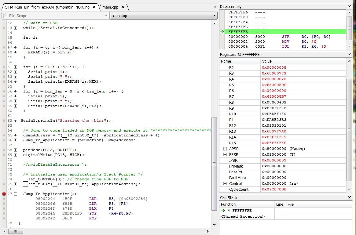
- Ozone EXRAM.JPG (158.19 KiB) Viewed 288 times
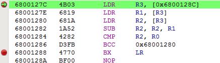
When stepping through it, it loops between 680015AC and ..15B2 “forever”, while looping no change in any of registers except PC and Cyclecount.
The R0 contains “3000”, R1=R2=0 (does it reads millis()==0??)
This is the code:
680015a8 <_Z5delaym>:

680015a8:	4b03      	ldr	r3, [pc, #12]	; (680015b8 <_Z5delaym+0x10>)

680015aa:	6819      	ldr	r1, [r3, #0]
680015ac:	681a      	ldr	r2, [r3, #0]
#include <libmaple/libmaple_types.h>

#include <libmaple/delay.h>
void delay(unsigned long ms) {

uint32 start = millis();

while (millis() - start < ms)

680015ae:	1a52      	subs	r2, r2, r1

680015b0:	4282      	cmp	r2, r0

680015b2:	d3fb      	bcc.n	680015ac <_Z5delaym+0x4>

;

}

680015b4:	4770      	bx	lr

680015b6:	bf00      	nop

680015b8:	680041b8 	.word	0x680041b8
680015bc <_Z7pinModeh13WiringPinMode>:
void pinMode(uint8 pin, WiringPinMode mode) {

gpio_pin_mode outputMode;

bool pwm = false;
if (pin >= BOARD_NR_GPIO_PINS) {

680015bc:	286f      	cmp	r0, #111	; 0x6f
Can you check in Ozone?
1- The VTOR register is getting the right value pointing to the exRAM NVIC table
2- the systick function is somewhere in that bin, and the NVIC pointer for systick looks correct
3- If interrupts are getting enabled again correctly.
EDIT:
This line looks strange to me, I can’t make sense of it:
080037B0 4B03 LDR R3, [0x080037C0]
I decided to strip down the HelloWorld into HelloToggle APP (intrpts in Loader enabled, flash and clock inits in init() commented out, VECTOR in boards to 0x68..) :
// HelloToggle APP for EXRAM

// Pito 01/2017 :)

// It Works !!!

void setup() {

int i;

pinMode(PC13, OUTPUT);

digitalWrite(PC13, HIGH);
for (i = 0; i < 20; i++) {
digitalWrite(PC13, LOW);
digitalWrite(PC13, HIGH);
}
digitalWrite(PC13, HIGH);
}
void loop() {
}
so the code is running from FSMC ram successfully, there is just something wrong with the interrupts or systick.
It probably has to do with the fact that the core is meant to generate code that executes after a reset, so initializing everything, while we are using it to generate code that gets called from another program.
Perhaps after some rest we can have a new look at it ![]()
I think objective one, that was to be able to run code in FSMC RAM has been achieved.
- HelloToggle.JPG (65.47 KiB) Viewed 302 times
The download version includes the SVD files for 103xx and 407something, also good to have.
Easy to setup and use. I started with it in 10 minutes inclusive searching for the SWD pin layout of the j-link blackbox pin header. There are 2 pictures world-wide with a correct view
Ozone with arduino IDE- it means you have to remember the phone numbers of the arduino build folders with the .elf file – it changes every time you close the sketch.. So with the same sketch you have to edit the path to .elf source all the time otherwise Ozone will not find the .elf.
Nice ide feature – I like it
Is there a fix for forcing the ide not to delete the build folder and not to rename it? It seems to me there was something long time back..
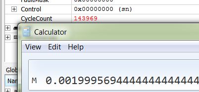
PS: ok, it is not as smooth as it seems. I spent another 10minutes searching for the “elapsed cycles/time” counter. After that I found out the cpucycles counter is editable, so you can zero it
- VTOR.JPG (39.16 KiB) Viewed 275 times
- delayloop.JPG (24.19 KiB) Viewed 266 times
VTOR.JPG
That is tricky
When the OFFSET is measured from memory_base (“bottom of the memory map”) which in case of “code” is 0, and in case of “SRAM” = 0x60000000, then you can place the vector table into the SRAM. Also the bit T=1 for “SRAM” sets MSB of the OFFSET[29..7].
The SRAM BANK starts 0x60000000 and it is 4x64MB=256MB long.
My EXRAM is from region3 (the third 64MB block from the SRAM BANK), so it address starts 0x68..
FSMC offers 4 fixed ChipSelects for SRAM regions called NE1,2,3,4 (as the SRAM regions start 0x60.., 0x64.., 0x68.., 0x6C..).
So my current understanding is – when SRAM’s bottom memory map starts at 0x60.. the VECTOR = 0x68000000 may work ..
(gdb) p/x ~(0b11 << 30 | 0b111111111)
$2 = 0x3ffffe00
that is the largest address that can be used.
When you set it to 0x68000000 it gets anded with that value and the result is someplace in outer space …
(gdb) p/x ~(0b11 << 30 | 0b111111111) & 0x68000000
$3 = 0x28000000
You can’t put the VTOR in external ram.
-rick
r – reserved
T=1 for SRAM
o – offset bits 29..7
VTOR

rrTo   oooo    oooo    orrr    rrrr

0000   1000    0000    0000    0000   = 0x08000000
0010 1000 0000 0000 0000 = ofset for 0x68000000
Ok, this is the STM32F103xx one from the above STM refman:
Bits 31:30 Reserved, must be kept cleared

Bits 29:9 TBLOFF[29:9] : Vector table base offset field. It contains bits [29:9] of the offset of the table base from memory address 0x00000000. When setting TBLOFF, you must align the offset to the number of exception entries in the vector table. The minimum alignment is 128 words. Table alignment requirements mean that bits[8:0] of the table offset are always zero. Bit 29 determines whether the vector table is in the code or SRAM memory region.

0: Code

1: SRAM

Note:   Bit 29 is sometimes called the TBLBASE bit.

Bits 8:0 Reserved, must be kept cleared1. the size of IRAM will be set 1K smaller in LOADER’s linker, the IRAM_VT will start at 0x2000FC00 – the lower 9 bits are 0.
2. After FMSC is alive in start_c.c we copy the range [0x68000000 .. end_of_the_vector_table] to [IRAM_VT .. IRAM_VT+vector_table_size] as-is
3. we set VTOR before jump to APP to 0x2000FC00
Is that correct?
PS:
2. we may copy the vector table from within the LOADER sketch.. it may work.. So no change in start_c.c is required. I am going to try
EDIT: fixed the addressess
1. the size of IRAM will be set 1K smaller in LOADER’s linker, the IRAM_VT will start at 0xFC00 – the lower 9 bits are 0.
2. After FMSC is alive in start_c.c we copy the range [0x68000000 .. end_of_the_vector_table] to [IRAM_VT .. IRAM_VT+vector_table_size] as-is
3. we set VTOR before jump to APP to 0xFC00
Is that correct?
PS:
2. we may copy the vector table from within the LOADER sketch.. it may work.. So no change in start_c.c is required. I am going to try
1. After reset the bootloader starts to fill the addresses from 0x20000000 with VT, where the vectors are all like 0x08xxxxx.
I can step through the bootloader, so I see it fill
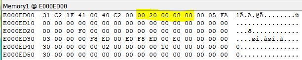
2. when I run till next BreakPoint – BP at the very beginning of the LOADER sketch, BP is placed BEFORE I do any copying of .bin to EXRAM, or copying of VT to IRAM (or I commented that out as well) I can see following:
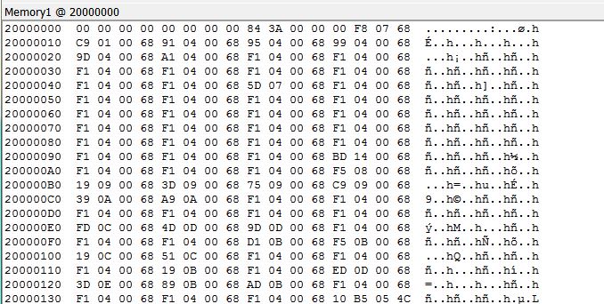
- Mem1.JPG (109.87 KiB) Viewed 288 times
1. After reset the bootloader starts to fill the addresses from 0x20000000 with VT, where the vectors are all like 0x08xxxxx.
I can step through the bootloader, so I see it fill
2. when I run till next BreakPoint – BP at the very beginning of the LOADER sketch, BP is placed BEFORE I do any copying of .bin to EXRAM, or copying of VT to IRAM (or I commented that out as well) I can see following:
Mem1.JPG
Somebody loads the VT with EXRAM vectors to 0x20000000, but I do not know who. That must be solved first – see my previous post
BTw, when briefly played with the APP while VT at 2000FC00 and VTOR=2000FC00 the result was negative – no systick.
But first I have to understand who fills the 0x6x.. vectors to 0x20000000
OMG!
unsigned char bin[] = {

0x00, 0xf8, 0x07, 0x68, 0xc9, 0x01, 0x00, 0x68, 0x91, 0x04, 0x00, 0x68,

0x95, 0x04, 0x00, 0x68, 0x99, 0x04, 0x00, 0x68, 0x9d, 0x04, 0x00, 0x68,

0xa1, 0x04, 0x00, 0x68, 0xf1, 0x04, 0x00, 0x68, 0xf1, 0x04, 0x00, 0x68,unsigned char bin[] = {
0x00, 0xf8, 0x07, 0x68, 0xc9, 0x01, 0x00, 0x68, 0x91, 0x04, 0x00, 0x68,
0x95, 0x04, 0x00, 0x68, 0x99, 0x04, 0x00, 0x68, 0x9d, 0x04, 0x00, 0x68,
0xa1, 0x04, 0x00, 0x68, 0xf1, 0x04, 0x00, 0x68, 0xf1, 0x04, 0x00, 0x68,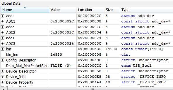
- data.JPG (63.61 KiB) Viewed 543 times
When the cpu resets it maps 0x20000000 to 0x0 …
0x0:	0x20005000

(gdb)

0x4:	0x20000109

(gdb) x/i *0x4

0x20000109 <__vector_table+265>:	ldr.w	pc, [pc, #-264]	; 0x20000004 <__vector_table+4>
I will doublecheck, but I think Loader is compiled for original VTOR.
New finding:
1. I set VTOR to 0x2000FC00 in the Loader, I see it at VTOR address correct
2. I jump to APP, stepping a while, VTOR holds
3. Then I run till BP which is set at the beginning of the first delay(3) loop
4. When it stops at that BP the VTOR is changed to 0x08002000..
I have to check the VTOR settings for APP build..
This changes my VTOR:
/**

* @brief Initialize the NVIC, setting interrupts to a default priority.

*/

void nvic_init(uint32 address, uint32 offset) {

680006f8:	b510      	push	{r4, lr}

* @param offset Offset from address.  Some restrictions apply to the

*               use of nonzero offsets; see the ARM Cortex M3

*               Technical Reference Manual.

*/

void nvic_set_vector_table(uint32 address, uint32 offset) {

SCB_BASE->VTOR = address | (offset & 0x1FFFFF80);

680006fa:	6098      	str	r0, [r3, #8]  <<<<<<<<<<<<<<<<<<<<<<< HERE
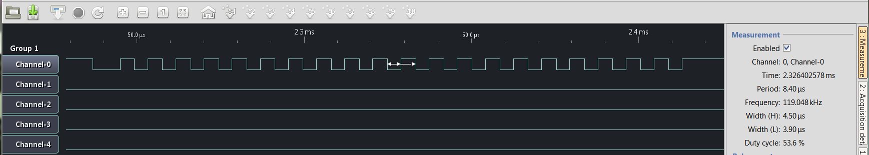
- 2msecs delay.JPG (24.43 KiB) Viewed 531 times
void nvic_set_vector_table(uint32 address, uint32 offset) {

//  SCB_BASE->VTOR = address | (offset & 0x1FFFFF80);

}This is the sketch which blinks in debugger (it goes via the Serial calls, but I see no HelloW chars in the TeraTerm Terminal, Loader prints ok before the jump into APP in EXRAM).
It does blink stand alone (off debugger) and I see no HelloW chars in the TeraTerm Terminal. The Loader prints ok before the jump to APP in EXRAM.
The variant with waiting on isConnected loops in debugger around the isConnected.
void setup() {

int i;

pinMode(PC13, OUTPUT);

digitalWrite(PC13, HIGH);
delay(5000);
Serial.begin(115200);
//while(!Serial.isConnected()){};
Serial.println("Hello World from EXRAM!");

Serial.println("Now we blink 17x..");
for (i = 0; i < 17; i++) {

digitalWrite(PC13, LOW);

delay(500);

digitalWrite(PC13, HIGH);

delay(500);

}
digitalWrite(PC13, HIGH);

Serial.println("Blinking stopped..");

}
void loop() {

}
COM22 is Serial USB from the LOADER, it prints out 8+8 bytes from APP’s in EXRAM to verify the FSMC works and the APP has been loaded into the EXRAM, COM5 is Serial1 from the HelloWorld sketch as above running in EXRAM.
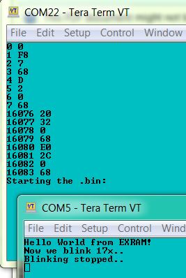
- HelloWorld from EXRAM.JPG (29.43 KiB) Viewed 500 times
VT at 0x2000FFC0 in reserved IRAM (reserved such the Loader’s IRAM ends in linker -4kB to be safe
STM32F103ZET6 @72MHz, SRAM 256kx16, 10ns, FSMC timing D1, A0.
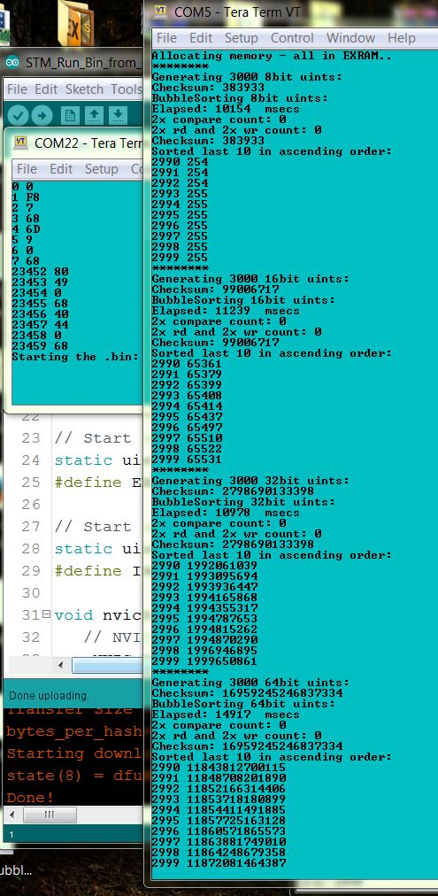
- BubbleSort in EXRAM.JPG (144.29 KiB) Viewed 499 times
Some more benchmarks (from this forum’s thread Dhrystone and Whetstone Benchmarks for STM32F103, first post), for the avoidance of any doubt the first results are from IRAM:
Starting Whetstone benchmark...

Loops: 1000Iterations: 1Duration: 20366 millisec.

C Converted Double Precision Whetstones: 4.91 MIPS
Starting Whetstone benchmark...
Loops: 1000Iterations: 1Duration: 179589 millisec.
C Converted Double Precision Whetstones: 556.83 KIPS
It is possible that the part that initializes the serial usb is called from one of the functions we disable, probably from setupClock()
It is also possible that the disconnect is not long enough for Windows to detect. In another thread Roger mentioned he had extended that time slightly because some people was having trouble with the enumeration.
If I understand right, you are first copying the NVIC table to int RAM, and then setting the VTOR value, is that right?
Do you do that in main() or in the sketch (setup() or loop())?
Dhrystone Benchmark, Version 2.1 (Language: C)

Execution starts, 300000 runs through Dhrystone
Execution ends

Microseconds for one run through Dhrystone: 57.35

Dhrystones per Second: 17437.22

VAX MIPS rating = 9.92

***
To load a sketch into ExRAM, you could write some sketch code to accept uploads via serial using the STM32-Flash protocol which the internal bootloader uses.
This would allow you to just reset the board ( which would run the uploader sketch), then just set the IDE to use the Serial upload method.
The protocol is fairly simple, and is well documented by ST and also we have the C and Python uploaders as a reference.
There is also an branch of the LeafLabs bootloader in their repo, which uploads using that protocol, ( in Leaflabs github repo) . Note, I dont know if that bootloader actually works because I never tried it ![]()
You could even add something to the protocol e.g to set a File Name, so that you could store in SD and retrieve later.
Now, about returning back to the loader, I have been thinking on a possible way, but there are many “if”…
I’m adding indexes to this to help in referencing, not that necessarily this are steps and they go in this order:
1.First, we know the stack from the loader and the stack from the App do not overlap, since one is in IRAM and the other in EXRAM, so we are not concerned about the loader stack getting corrupt.
2.Right before loading the App, we change the stack pointer to the EXRAM one.
3.Next we call the APP (the PC should be saved to the stack automatically, isn’t it?) Rick knows more how the internals of this MCUs work, so he may be able to help on this.
4.IF the PC is saved automatically when calling the App, then the first entry at the top of the new stack is the return point to get back to the loader sketch.
4b. IF that is not the case, we could read the PC before calling the user code, add as many bytes as needed to the get the right return address, and then save it to the top of the new stack before calling the App code.
5.The app could exit by just calling the address saved at the top of the EXRAM stack. That is a known address, so we dont even have to care what else is in that stack by now, only reading the first entry and jumping to it should hopefully be enough.
6.IF we can return back to the loader, we need to be able upon the return to point the SP register back to the bottom of the Loader stack (remember point 2 above, we overwrite the SP with the EXRAM top of stack). To do this, I think we should save the stack to a uint32 variable right before point 2, that is right before overwritting it with the EXRAM stack. Then the instruction after the jump to the App function, should be followed by an instruction that reads the value from that variable, and write it to SP, and the loader can continue running like normal.
Does anyone see any flaw on this process?
Pito, I think you can verify if the return PC is saved to the top of the new stack with the debugger, by placing a breakpoint right at the start of the App, and checking the top of the stack content, right?
I presumed that Pito must have already been handling the stack etc before jumping to the Application code, as the sketch must be copying the Application from its static array into flash before it jumps
Returning back could be a bit tricky as you’d need to restore all registers etc as the Application will have left them in some unknown state.
To start with, I’d presume that you need to reboot to exit from your application code, and then sort out how to return later.
(As I presume the Application code, would need to have the Return feature built into it, as the sketch code, and its interrupts etc will no longer be functioning as soon as the Application code starts running.)
I think “finishing” the function would require all registers to be pushed to the stack before the Jump to the Application, also the PC would need to be pushed onto the Application stack, so that the Application would know where to jump back to.
So the only way people would like imho is to use a media connected to the MCU for the storing of binaries, ie SDcard, internal flash, external flash, usb flash, punch tape
Returning to xLOADER from EXRAM’s APP is vital, SO IT MUST BE SOLVED WITH HELP OF THE EXPERTS HERE, as then you can create an xLOADER (I do not want to name it an “OS” as it might happen I would be banned here ![]() ) which, when connected to an SDcard via SdFat, will list for example:
) which, when connected to an SDcard via SdFat, will list for example:
Hello Roger from xLOADER v3.12 !

> dir

24567 APPs found

APP1.bin APP2.bin ...

.. APP24567.bin

> run APP3.bin

Hello World from EXRAM!!!

> run APP2238.bin

Whetstone..

> date

2017 01 09

> time

10:02 AM

>
// THE xLOADER v1.01

//

// LOADS an USER APP binary into the EXRAM and RUNS the APP off the EXRAM

// The APP must fit into EXRAM (text, data, bss, heap, stack)

// The bin.h includes the APP.bin in form of (for example):

//

//    static const unsigned char bin[] = {

//       0x00, 0xf8, 0x07, 0x68, 0x39, 0x06, 0x00, 0x68, 0x91, 0x09, 0x00, 0x68,

//       0x95, 0x09, 0x00, 0x68, 0x99, 0x09, 0x00, 0x68, 0x9d, 0x09, 0x00, 0x68,

//       ..

//       0xb8, 0x52, 0x00, 0x68, 0x78, 0x4d, 0x00, 0x68

//    };

//    unsigned int bin_len = 25844;

//

// The bin.h could be generated from APP.bin by a tool called "xxd"

//

// More info at stm32duino forum

// No warranties of any kind. Provided as is. Use at your own risk.

// by Pito January 8th 2017

//
#include "bin.h"
__attribute__( ( always_inline ) ) static inline void __set_CONTROL(uint32_t control) {

__asm volatile ("MSR control, %0" : : "r" (control) : "memory");

}

__attribute__( ( always_inline ) ) static inline void __set_MSP(uint32_t topOfMainStack) {

__asm volatile ("MSR msp, %0\n" : : "r" (topOfMainStack) : "sp");

}
typedef  void (*pFunction)(void);

#define ApplicationAddress       ((uint32_t)0x68000000)

#define __IO volatile

pFunction Jump_To_Application;

__IO uint32_t JumpAddress;
// Start of FSMC SRAM BANK 1, REGION 3

static uint8 *const sram_start8 = (uint8*)0x68000000;

#define EXRAM8(x) (*(sram_start8+x))
// Start of the APP Vector Table in IRAM

static uint8 *const iram_VT = (uint8*)0x2000FC00;

#define IRAMVT(x) (*(iram_VT+x))
void nvicDisableInterrupts() {

NVIC_BASE->ICER[0] = 0xFFFFFFFF;

NVIC_BASE->ICER[1] = 0xFFFFFFFF;

NVIC_BASE->ICPR[0] = 0xFFFFFFFF;

NVIC_BASE->ICPR[1] = 0xFFFFFFFF;
/* disable the systick, which operates separately from nvic */

systick_disable();

}
void setup() {
Serial1.begin(115200);
// wait on USB

// while(!Serial.isConnected()){};
int i;

uint32 elapsed = micros();

// copy the APP.bin into the EXRAM

for (i = 0; i < bin_len; i++) {

EXRAM8(i) = bin[i];

}

elapsed = micros() - elapsed;

Serial1.print("Loading the APP.bin took ");

Serial1.print(elapsed);

Serial1.print(" usecs");

Serial1.println(" ");
// print out first 8 and last 8 bytes of the APP binary stored in EXRAM for a check

// if the FSMC does not work properly, the "FF"s will be returned

for (i = 0; i < 8; i++) {

Serial1.print(i);

Serial1.print(" ");

Serial1.println(EXRAM8(i), HEX);

}

for (i = bin_len - 8; i < bin_len; i++) {

Serial1.print(i);

Serial1.print(" ");

Serial1.println(EXRAM8(i), HEX);

}
// copy the APP Vector_Table to IRAM (ie. starting from 0x2000FC00)

for (i = 0; i < 512; i++) {

IRAMVT(i) = bin[i];

}
Serial1.println("Starting the APP.bin:");

delay(10);  // wait till Serial prints all the chars out
/* jump to USER APP code loaded in EXRAM memory and execute it!! */
JumpAddress = *(__IO uint32_t*) (ApplicationAddress + 4);

Jump_To_Application = (pFunction) JumpAddress;
nvicDisableInterrupts();
// set the new VTOR

*(int volatile*)0xE000ED08 = (volatile uint32_t) 0x2000FC00;
/* initialize USER APP Stack Pointer */

__set_CONTROL(0); // Change from PSP to MSP

__set_MSP(*(__IO uint32_t*) ApplicationAddress);
Jump_To_Application();

}
void loop() {

}
Edit. I just noticed you posted while I was writing this. So I’ve not read your code yet.
I know EXRAM is volatile, so I presumed that you wanted to store the Application code on a SD card, and then load in whichever Application you have on the SD.
My thought, was also that you would want a simple way to create the Application, in the IDE and upload it to the board (for the board to store in EXRAM and also in SD), or perhaps, straight to SD and then load EXRAM from SD later.
Anyway, back to returning from the Jump to the Application in EXRAM:
I think…
In order to return, you will need to push all the regs onto the stack, then switch stack to the EXRAM stack and do your other setup e.g. VTOR table, and then, push the return address (PC + x ) onto the EXRAM stack, and them Jump to the EXRAM Application start
When the application has finished, you will need to pull the return address PC from the EXRAM stack, and then jump to that location.
The Main code then needs to restore its unwind, change the stack address and restore registers from stack etc
Jump_To_Application();Let us think for a while.
A code samples will be welcomed. But better when you own a board with a SRAM on it. Porting to other board is easy (when you have done it once
Usually this kind of exercise ends up with something called **ix kernel
But for 2017 let us set a goal to create an xLOADER which can load/run/reload/rerun SDcard stored APP binaries based on a very simple “command line interpreter” as depicted above.. A Sunday’s exercise when we tackle the return from an APP running in the EXRAM back to the CLI (command line interpreter)..
Here is a GUIDE – a short intro we may enhance slowly http://www.stm32duino.com/viewtopic.php … 100#p22119
1Mx16 10ns

- mem2MB.jpg (7.6 KiB) Viewed 436 times
Loading the APP.bin took 7490 usecs

0 0

1 F8

2 7

3 68

4 39

5 6

6 0

7 68

25836 B8

25837 52

25838 0

25839 68

25840 78

25841 4D

25842 0

25843 68

Starting the APP.bin:

Dhrystone Benchmark, Version 2.1 (Language: C)

Execution starts, 300000 runs through Dhrystone
Execution ends

Microseconds for one run through Dhrystone: 57.41

Dhrystones per Second: 17418.90

VAX MIPS rating = 9.91

***
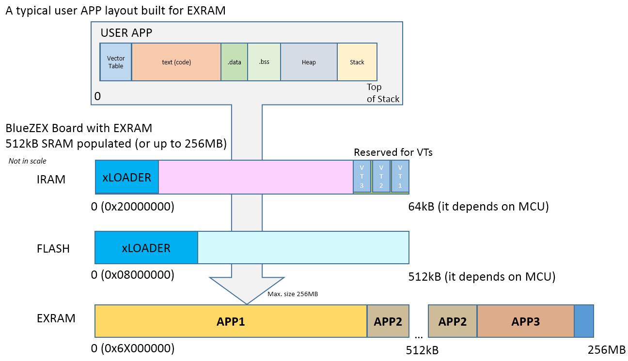
- EXRAM_Guide_1.JPG (94.52 KiB) Viewed 540 times
Jump_To_Application();Would be great if you may simulate the jumpin-jumpout on your board.
The xLOADER with SdFat will be around 38kB flash and 6kB IRAM (derived from the readCSV example).
The smallest APP I’ve built – toggling a pin – is 15kB
Would be great if you may simulate the jumpin-jumpout on your board.
The xLOADER with SdFat will be around 38kB flash and 6kB IRAM (derived from the readCSV example).
The smallest APP I’ve built – toggling a pin – is 15kB
https://www.aliexpress.com/item/2Pcs-IS … 77141.html
The memory voltage (5V or 3.3V) usually differs based on a 1-2 different letters in the part name (sometimes a letter after the dash). Even large suppliers have problems to distinguish..
BlueZEX board with an SDcard socket attached, @72MHz, SPI1 @36MHz, in EXRAM.
Look at the Free Stack message
Loading the APP.bin took 15829 usecs

0 0

1 F8

2 7

3 68

4 A1

5 2C

6 0

7 68

39264 20

39265 28

39266 30

39267 38

39268 A0

39269 7F

39270 0

39271 68

Starting the APP.bin:
Use a freshly formatted SD for best performance.
Type any character to start

FreeStack: 472455

Type is FAT32

Card size: 8.03 GB (GB = 1E9 bytes)
Manufacturer ID: 0X1B

OEM ID: SM

Product: 00000

Version: 1.0

Serial number: 0X8C5663D3

Manufacturing date: 6/2015
File size 5 MB

Buffer size 8192 bytes

Starting write test, please wait.
write speed and latency

speed,max,min,avg

KB/Sec,usec,usec,usec

1140.37,96194,5806,7164

1048.93,96772,5814,7789

1073.26,97157,5812,7612

1065.48,96412,5814,7668

1098.51,96416,5810,7439

1078.13,97167,5821,7579
Starting read test, please wait.
read speed and latency

speed,max,min,avg

KB/Sec,usec,usec,usec

856.26,11804,9471,9559

856.40,10969,9472,9556

856.40,11138,9477,9556

856.40,10954,9451,9556

856.40,11139,9475,9557

856.55,11133,9473,9556
Done

Type any character to start
this one ranged from £11.46 to £12.77
https://www.aliexpress.com/item/Free-sh … 0.0.4i6Xle
btw there’s a slightly smaller pcb 407VET variant, no sram pads underneath.
order date to delivery varied from 18 to 33 days
stephen
if you follow the links for the variant below, there’s a ‘user guide’, schemetic and sample code.(not sure for which board)
code probably for SPL and uvision5(??)
soldering 0603 resistors, intending to use finger nail holding one in place, tiddlywinks, find resistor
stephen
from EXRAM, allocated ~260kB (10k records) for FIFO buffer:
Sketch uses 37,544 bytes (7%) of program storage space. Maximum is 524,288 bytes.

Global variables use 296,496 bytes of dynamic memory.A 50% speed up with read
write speed and latency

speed,max,min,avg

KB/Sec,usec,usec,usec

1073.50,97293,5571,7617

1131.34,96151,5570,7227

1157.28,96051,5570,7062

1061.64,96890,5570,7699

1086.09,96610,5570,7530

1108.75,96572,5570,7375
Starting read test, please wait.
read speed and latency

speed,max,min,avg

KB/Sec,usec,usec,usec

1278.04,7996,5729,6405

1279.34,8089,5723,6396

1279.34,8081,5744,6399

1279.02,8081,5723,6400

1279.34,8103,5726,6401

1278.69,8741,5720,6401
Done

Type any character to start
http://infocenter.arm.com/help/topic/co … /ATPCS.pdf
I haven’t finished it yet, but so far I understand the job of saving the SP and registers is left to the Called routine, not the calling one.
Since from the loader the called routine is the startup assembler code the linker script places at the start, and we change the SP already before calling it, I think we need to manually provision for saving that before the call.
R0-R3 do not need to be preserved by the called routine. So we need to do this from the loader:
1. Save R4-R11 to the stack
2. Save SP to a known iram position (just a pointer type variable should work).
3. Save a return address somewhere (exRAM or IRAM?).
4. Change SP
5. Call App
—-
6. (Return address pointing to this instruction). Load SP from variable in step 3.
7. Pop R4-R11 from stack.
8. Reconfigure NVIC VTOR.
9. Enable interrupts
From the app, to return, we have to:
1. Disable interrupts.
2. read the address saved in step 3 above.
3. load it to the PC, that will take the PC to step 6.
The peripherals state will be indeterminate at that point. Specially the USB peripheral, and any other using a buffer, since the buffer address was probably changed, and other configuration registers too.
EDIT: The more I think about it, the more I think it may be better to reset the MCU to restart the program in flash when the app is finished like Roger suggested, otherwise there too many things to control.
Of course you can make sure the Loader and the app do not use the same peripherals, so the peripherals for the loader have not changed state on return, but that limits what you do. Seems better to just reboot and let the loader pick a new app.
A 50% speed up with read
write speed and latency

speed,max,min,avg

KB/Sec,usec,usec,usec

1073.50,97293,5571,7617

1131.34,96151,5570,7227

1157.28,96051,5570,7062

1061.64,96890,5570,7699

1086.09,96610,5570,7530

1108.75,96572,5570,7375
Starting read test, please wait.
read speed and latency

speed,max,min,avg

KB/Sec,usec,usec,usec

1278.04,7996,5729,6405

1279.34,8089,5723,6396

1279.34,8081,5744,6399

1279.02,8081,5723,6400

1279.34,8103,5726,6401

1278.69,8741,5720,6401
Done

Type any character to start
In big OSes the kernel is isolated from user’s APPs physically, so the kernel context and APP one is preserved.
We may agree the only peripheral xLOADER is using is the Serial1. That is the xLOADER’s console. I already have CL parser working in the xLOADER, I will update xLOADER soon.
### Hello from xLOADER v1.02 ! ###

Usage:

help

run APP1

test

test1 param
> help

Usage:

help

run APP1

test

test1 param
> test

This is the test..

> test1 hello1234

This is the test1..

Parameter: hello1234

> run DHRYSTONE

Loading the DHRYSTONE took 8201 usecs

0 0

1 F8

2 7

3 68

4 39

5 6

6 0

7 68

25836 B8

25837 52

25838 0

25839 68

25840 78

25841 4D

25842 0

25843 68

Starting the DHRYSTONE ...
Dhrystone Benchmark, Version 2.1 (Language: C)

Execution starts, 300000 runs through Dhrystone
Execution ends

Microseconds for one run through Dhrystone: 57.35

Dhrystones per Second: 17437.23

VAX MIPS rating = 9.92

***
Reading from file via 8192b large buffer.
No bin.h used anymore, great !!!
Edit: added dir
### Hello from xLOADER v1.03 ! ###

Usage:

help

dir

run APP.bin

> dir

Root dir:

Dhrystone.bin

STM_Dhrystone128.ino.bin

STM_HelloToggle_fromEXRAM.ino.bin

STM_SDLOGGER_FreeRtos_FIFO__FIRFILTER.ino.bin

STM_Whetstone.ino.bin

STM_bench.ino.bin

STM_BubbleSort_EXRAM_ALL.ino.bin

STM_Dhrystone.ino.bin

> run Dhrystone.bin

Reading file..

Loading the Dhrystone.bin 25844 bytes large took 17531 usecs

First 8 bytes in EXRAM: 0 F8 7 68 39 6 0 68

Starting the Dhrystone.bin ...
Dhrystone Benchmark, Version 2.1 (Language: C)

Execution starts, 300000 runs through Dhrystone
Execution ends

Microseconds for one run through Dhrystone: 57.35

Dhrystones per Second: 17437.23

VAX MIPS rating = 9.92

***
EXRAM, 200×200 pixels, converts to .bmp image, saves the .bmp on the Sdcard.
Double precision calcs (I hope so..). A torture for the stm32 @128M.
Color mapping is still a crap, but you get the feeling of eighties, when talking performance..
> run Mandelbrot.bin

Reading file..

Loading the Mandelbrot.bin 32960 bytes large took 22997 usecs

First 8 bytes in EXRAM: 0 F8 7 68 21 22 0 68

Starting the Mandelbrot.bin ...
Allocated 120000 bytes for image buffer..

Mandelbrot starts..

Elapsed 837912 msecs

Writing .bmp to SDcard..

Done..
 Allocated 120000 bytes for image buffer..

Mandelbrot starts..

Elapsed 101974 msecs

Writing .bmp to SDcard..

Done..1. APP runs off the internal IRAM, and uses HEAP in EXRAM
2. xLOADER’s ram is placed on top of IRAM
3. xLOADER runs as usual off the flash, and loads the APP into IRAM (0x20000000).
You may see the VT addresses below point to the internal IRAM.
Dhrystone and Mandelbrot 200×200, all at 128MHz.
> run Dhrystone.bin

Reading file..

Loading the Dhrystone.bin 25844 bytes large took 33646 usecs

First 8 bytes in EXRAM: 0 DC 0 20 39 6 0 20

Starting the Dhrystone.bin ...
Dhrystone Benchmark, Version 2.1 (Language: C)
Execution starts, 300000 runs through Dhrystone
Execution ends
Microseconds for one run through Dhrystone: 9.50
Dhrystones per Second: 105309.90
VAX MIPS rating = 59.94
***
> run Mandelbrot.bin
Reading file..
Loading the Mandelbrot.bin 32976 bytes large took 43246 usecs
First 8 bytes in EXRAM: 0 DC 0 20 21 22 0 20
Starting the Mandelbrot.bin ...
Allocated 120000 bytes for image buffer..
Mandelbrot starts..
Elapsed 104978 msecs
Writing the .bmp to SDcard..
Done..
In this session
### Hello from xLOADER v1.03 ! ###

Usage:

help

dir

run APP.bin
> dir

Root dir:

DATA.BMP

STM_Dhrystone128.ino.bin

STM_HelloToggle_fromEXRAM.ino.bin

STM_SDLOGGER_FreeRtos_FIFO__FIRFILTER.ino.bin

STM_Whetstone.ino.bin

STM_bench.ino.bin

STM_BubbleSort_EXRAM_ALL.ino.bin

Dhrystone.bin

STM_Mandelbrot_SeaHorseValley.ino.bin

Mandelbrot.bin

Dhrystone_jmp_rst.bin

> run Dhrystone_jmp_rst.bin

Reading file..

Loading the Dhrystone_jmp_rst.bin 25932 bytes large took 33657 usecs

First 8 bytes in EXRAM: 0 DC 0 20 79 6 0 20

Starting the Dhrystone_jmp_rst.bin ...
Dhrystone Benchmark, Version 2.1 (Language: C)

Execution starts, 300000 runs through Dhrystone
Execution ends

Microseconds for one run through Dhrystone: 9.56

Dhrystones per Second: 104601.60

VAX MIPS rating = 59.53

***
Dhrystone Benchmark, Version 2.1 (Language: C)

Execution starts, 300000 runs through Dhrystone
Execution ends

Microseconds for one run through Dhrystone: 9.56

Dhrystones per Second: 104601.56

VAX MIPS rating = 59.53

***
### Hello from xLOADER v1.03 ! ###

Usage:

help

dir

run APP.bin
>
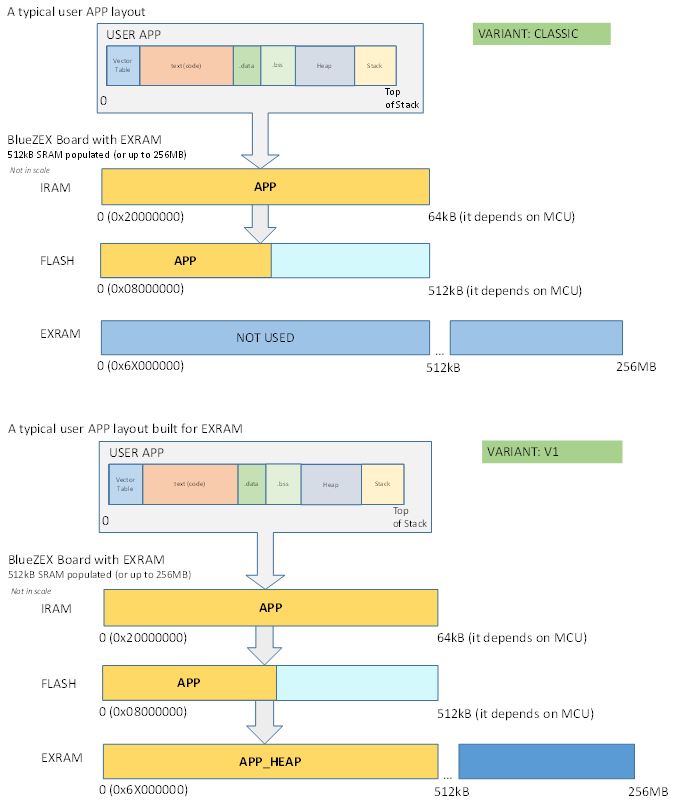
- EXRAM_VARIANTS_CLASSIC_V1.JPG (65.17 KiB) Viewed 885 times
https://forum.arduino.cc/index.php?topi … rdseen#new
That could easily be run with the CP/M_RAM placed into the 512kB Heap.
At 128MHz it will be faster a bit.. ![]()
https://forum.arduino.cc/index.php?topi … rdseen#new
That could easily be run with the CP/M_RAM placed into the 512kB Heap.
At 128MHz it will be faster a bit.. ![]()
I think the ZET6 board with 512 or 1024kB of external ram is an ideal and cheap platform for such retro-computing stuff..
I think the ZET6 board with 512 or 1024kB of external ram is an ideal and cheap platform for such retro-computing stuff..
https://hackaday.com/2017/03/25/cpm-8266/
https://github.com/Dreamy16101976/cpm4nano
FoxyLab uses some avr register settings there, so it will not compile straight to stm32duino. Needs some tweaking.
Also the 64kB mem could be placed to heap here..

