At the moment, the F072 is not one that has been exported from the Cube, and the files from the Cube need some modification (patching) before they can be used as an Arduino “core”, but this does theoretically make it easier to add new processors.
One big caveat is at the moment, this is at pre-alpha stage and only things like GPIO are working. Though I see today that Vassilis now has SPI working and tested on the F103
If you have a F072 device, perhaps you can volunteer to help with developing and testing of the new core on that processor.
I suspect there will be some difference in the setup of the PLL’s and various other clocks etc etc that may prevent the F103 bootloader working on the F072
Re: HAL MX not using the bootloader
I think you are asking why the HAL MX core doesn’t use the bootloader
We’ve not got around to modifying the HAL MX core so that it will run at a different start address
Theoretically we just need to change the start vector to the address the bootloader jumps to 0x8002000 and the HAL MX core may work with the bootloader.
However the start vector is hard coded into one of the HAL headers, so we’d need to patch that header every time we do a re-export of the HAL files from the Cube.
We already need to patch main.c, so I suspect in the fullness of time, we’ll need to write a suite of patches as part of the core creating / regeneration process
However, no one has had time to work on the HAL MX core, and only recently @vassilis has been able to move things forward a bit (following on from @sheepdoll’s original work)
http://www.stm32duino.com/viewtopic.php?f=46&t=990
A few people are working on an Arduino “core” using the STM Cube. However only Vassilis has managed to make the USB Serial CDC work.
@sheepdoll has issues with the CDC on OSX.
I’ve not managed to get the Cube to export valid code after enabling the USB ![]()
I took the USB CDC example from FW1.5.0, which was used by STM32CubeMX for code generation. I just can’t understand why wouldn’t it work with the Cube if it work just fine in the examples provided by ST.
Next step is to clean up this USB CDC thing and adding a bootloader. Any pointer on the source code of bootloader that works for STM32 from your (or anyone else’s) repository?
I suspect as the HAL etc generates large binaries, it may not be suitable to write a bootloader.
I know @jcw was writing a new bootloader, but I don’t think he ever finished
You could also look at libopencm3 as it has usb code.
You will need to search in the repo core code if you want to find the sequence that the maple_upload tool sends
But this is not standard for the Arduino. I don’t know how its handled on an AVR arduino, you would need to post to the Arduino.cc forum to find out.
I just use gcc that comes with the Windows Arduino IDE, I think its arm-none-eabi-gcc\4.8.3-2014q1
But I’ve not tired to compile recently. However other people have compiled in the last day or two on OSX and not had any issues
Now that I got one platform to work to be used as reference, I can move forward to port the code to STM32F072. But before doing this, I have one remaining question. During the flash upload, is there a way to automate this instead of pressing DFU and reset buttons to enter flashing mode? I am sure you thought about this and I’d like to hear your ideas about it. Maybe I can help to make it happen.
I am still undecided yet whether I will go with DFU, CDC ACM with a serial bootloader.
- STM32CubeMX is a great tool to understand how to use STM32 HAL Driver by generating codes with various peripherals’ configuration. But, that’s it! Nothing works out of the box without a little touch here and there. So basically, I generated some code from it, and then copy and paste anything I need and move on with my own fix.
- I use STM32F0xx CMSIS V2.2.3 / 29-January-2016, STM32F0xx_HAL_Driver V1.3.1 / 29-January-2016, and STM32_USB_Device_Library V2.4.2 / 11-December-2015. I tried to include the latest libraries as I could. These releases work just fine for the moment.
- I use arm-none-eabi-gcc V5.2.1, not sure what version of GCC included within Arduino IDE 1.6.5? Which Arduino IDE should I use to test Arduino_STM32?
- My platform is STM32F072B-DISCO, which has STM32F072RBT6 chip on it and an on-board ST-Link V2/V2-1. There are something in the Makefile I need to get rid of, if we want to make the STM32F0xx HAL Driver to build for other F0xx variants (not a priority for now).
- I got the USB CDC ACM to work, with _write() and _read() function stubs. So, printf(), scanf(), and getchar() work just fine. I have also disable stdin, stdout, and stderr buffering. I would like to make getchar() as non-blocking, but I have no idea what to modify in the library. Anyone?
- A snippet from Hubert Denkmair (http://stackoverflow.com/questions/2828 … stm32-f072) is included in the system:
#include <stdint.h>

#include "stm32f0xx_hal.h"
#define SYSMEM_RESET_VECTOR 0x1fffC804
#define RESET_TO_BOOTLOADER_MAGIC_CODE 0xDEADBEEF
#define BOOTLOADER_STACK_POINTER 0x20002250uint32_t dfu_reset_to_bootloader_magic;
void __initialize_hardware_early(void)
{
if (dfu_reset_to_bootloader_magic == RESET_TO_BOOTLOADER_MAGIC_CODE) {
void (*bootloader)(void) = (void (*)(void)) (*((uint32_t *) SYSMEM_RESET_VECTOR));
dfu_reset_to_bootloader_magic = 0;
__set_MSP(BOOTLOADER_STACK_POINTER);
bootloader();
while (42);
} else {
SystemInit();
}
}void dfu_run_bootloader()
{
dfu_reset_to_bootloader_magic = RESET_TO_BOOTLOADER_MAGIC_CODE;
NVIC_SystemReset();
}
http://www.stm32duino.com/viewtopic.php?f=46&t=1027
It would be better if you could assist Vassils and @sheepdoll with the HALMX core, rather then starting a new one based on the HAL
The setup() and loop() functions are called by main.c (each board variant has a complete copy of the HALMX files as exported by the Cube)
Actually at the moment I’m now getting this error
arm-none-eabi-g++: error: unrecognized command line option '-CC -mcpu=cortex-m3'
https://github.com/ekawahyu/HALMX_Arduino_STM32
I stumbled across a couple of quite annoying issues, like STM32CubeMX keeps renaming and overriding *.S into *.s. This will never build on Arduino IDE because it looks for *.S file. I tried to patch the CMSIS repository directly by changing all startup files from .s suffix to .S, but it doesn’t seem to work.
Another issue is related to stlink_upload. It looks for libusb-1.0.0.dylib under /usr/local/lib, which I don’t have. My macports installation is on its default /opt/local/lib for everything. I also tried to create a symlink:
sudo ln -s /opt/local/lib/libusblibusb-1.0.0.dylib /usr/local/lib/libusb-1.0.0.dylib
You could try recompiling it on your machine and see if it finds the correct static library
We see this with the Maple mini in libmaple as the SWD pins are reassigned to GPIO so that more GPIO pins are available.
So you have to use connect under reset and manually reset the board when moving from Bootloader uploads to STLink uploads on the Maple mini
Though after you have done one STLink upload it fixes the issue as the SWD pins are not reassigned in STLink upload in libmaple
It is weird. Only power cycle can make it execute code in the flash after uploading from Arduino. Sometimes I also got this error:
2016-05-20T14:10:56 INFO src/usb.c: -- exit_dfu_mode

2016-05-20T14:10:56 INFO src/common.c: Loading device parameters....

2016-05-20T14:10:56 INFO src/common.c: Device connected is: F07x device, id 0x20016448

2016-05-20T14:10:56 INFO src/common.c: SRAM size: 0x4000 bytes (16 KiB), Flash: 0x20000 bytes (128 KiB) in pages of 2048 bytes

2016-05-20T14:10:56 INFO src/common.c: Ignoring 4 bytes of 0xff at end of file

2016-05-20T14:10:56 INFO src/common.c: Attempting to write 21708 (0x54cc) bytes to stm32 address: 134217728 (0x8000000)
Flash page at addr: 0x08000000 erased
Flash page at addr: 0x08000800 erased
Flash page at addr: 0x08001000 erased
Flash page at addr: 0x08001800 erased
Flash page at addr: 0x08002000 erased
Flash page at addr: 0x08002800 erased
Flash page at addr: 0x08003000 erased
Flash page at addr: 0x08003800 erased2016-05-20T14:10:57 INFO src/common.c: Finished erasing 11 pages of 2048 (0x800) bytes
2016-05-20T14:10:57 INFO src/common.c: Starting Flash write for VL/F0/F3 core id
2016-05-20T14:10:57 INFO src/common.c: Successfully loaded flash loader in sram
Flash page at addr: 0x08004000 erased
Flash page at addr: 0x08004800 erased
Flash page at addr: 0x08005000 erased2016-05-20T14:10:59 ERROR src/common.c: flash loader run error
2016-05-20T14:10:59 ERROR src/common.c: run_flash_loader(0x8000000) failed! == -1
stlink_fwrite_flash() == -1
I am now working on the DFU support and need to make the USB CDC to work within Arduino IDE.
@rogerclark: Do you think we can move this thread and change the title somehow as I have logged a lot of work and notes for STM32F072B-Disco platform development? I just thought that it is not appropriate to stay under General discussion anymore. Thanks.
EDIT: Confirmed, built-in OpenOCD works! The Arduino SAMD Board (32-bit Cortex-M0+) needs to be installed to make it work.
I started to see this ld warning, should I be worried about this warning?
packages/arduino/tools/arm-none-eabi-gcc/4.8.3-2014q1/bin/../lib/gcc/arm-none-eabi/4.8.3/../../../../arm-none-eabi/bin/ld: warning: changing start of section .rodata by 4 bytes

/packages/arduino/tools/arm-none-eabi-gcc/4.8.3-2014q1/bin/../lib/gcc/arm-none-eabi/4.8.3/../../../../arm-none-eabi/bin/ld: warning: changing start of section .rodata by 4 bytes

/packages/arduino/tools/arm-none-eabi-gcc/4.8.3-2014q1/bin/../lib/gcc/arm-none-eabi/4.8.3/../../../../arm-none-eabi/bin/ld: warning: changing start of section .rodata by 4 bytes
I am planning to call CDC_Transmit_FS() periodically, with timer interrupt, or through SysTick. So, we need a transmit buffer to do this. I had a quick test by simply sending come characters and seemed that my Mac was happy about it ![]() I can see that you commented out some code with tx buffer in there, is it a work in progress of sending data in bulk? What is the best timing for sending it? Every 1ms, 10ms? Hooking up with SysTick will be the simplest way to do it.
I can see that you commented out some code with tx buffer in there, is it a work in progress of sending data in bulk? What is the best timing for sending it? Every 1ms, 10ms? Hooking up with SysTick will be the simplest way to do it.
The solution I gave you is temporary. That is why I haven’t sent a PR yet. I am working on the USBSerial tx buffer.
I spoke to Vassilis on Skype chat
And I’m now using a modified version of the code to fix the USB send issue
size_t USBSerial::write(const uint8_t *buffer, size_t size)

{

unsigned long timeout=millis()+5;

if(hUsbDeviceFS.dev_state == USBD_STATE_CONFIGURED)

{

while(millis()<timeout)

{

if(CDC_Transmit_FS((uint8_t*)buffer, size) == USBD_OK)

{

return size;

}

}

}

return 0;

}
I started to see this ld warning, should I be worried about this warning?
packages/arduino/tools/arm-none-eabi-gcc/4.8.3-2014q1/bin/../lib/gcc/arm-none-eabi/4.8.3/../../../../arm-none-eabi/bin/ld: warning: changing start of section .rodata by 4 bytes

/packages/arduino/tools/arm-none-eabi-gcc/4.8.3-2014q1/bin/../lib/gcc/arm-none-eabi/4.8.3/../../../../arm-none-eabi/bin/ld: warning: changing start of section .rodata by 4 bytes

/packages/arduino/tools/arm-none-eabi-gcc/4.8.3-2014q1/bin/../lib/gcc/arm-none-eabi/4.8.3/../../../../arm-none-eabi/bin/ld: warning: changing start of section .rodata by 4 bytes
Just off the top my head, I had to modify the code that defines the vector table offset, as its hard coded to 0x00, and hence the code wont work with a bootloader
I also had to make a new .ld file to match the bootloader offset 0x2000
And of course we have to modify main.c, and possibly other files.
So there is no way that we are ever going to just be able to export the cube files and make a new core, or update an existing core, without either manually patching the files, or perhaps have some automated patch system
If we give users the freedom to generate the code on their own through STM32CubeMX, then we can’t really have hundreds of patches available for every possible configuration for them all. I don’t know, I am running out of idea… ![]()
Almost 99% of files inside CubeMX are steady for a specific STM32 family. Normally the files in the upper project’s directory are generated by CubeMX.
Which other files are normally moved ?
Can we safely just delete the Cube generated verison of system_stm32f1xx.c and use one we create ourselves (in another location) ?
(though looking at what else is in this file, It looks possible that a new release of the Cube could generate different code into system_stm32f1xx.c, as there is lots of config stuff in there)
I’ve realised that this thread is crossing over with the HAL MX roadmap thread
I think we should probably discuss generic Cube related issues in the other thread..
I’m about to post there now, as we need to work out how to handle the additional pin modes that are not in the core Arduino API
i.e like INPUT_PULLDOWN
Thanks
Roger
Just off the top my head, I had to modify the code that defines the vector table offset, as its hard coded to 0x00, and hence the code wont work with a bootloader
I also had to make a new .ld file to match the bootloader offset 0x2000
And of course we have to modify main.c, and possibly other files.
So there is no way that we are ever going to just be able to export the cube files and make a new core, or update an existing core, without either manually patching the files, or perhaps have some automated patch system
#define VECT_TAB_OFFSET  0x0 /*!< Vector Table base offset field.

This value must be a multiple of 0x200. */
#define VECT_TAB_OFFSET  0x0 /*!< Vector Table base offset field.

This value must be a multiple of 0x200. */
https://github.com/arduino/dfu-utils-cr … er/distrib
I am still working on the dfu_upload scripting for Windows, but I got some weird issue with dfu_upload script for Linux. It is able to send the magic word ‘1EAF’ over the serial port with ‘echo’, but it always says Device or Resource Busy the next time I try to execute this again. I have to wait for at least 40 seconds before I can hit upload button to flash the binary. What am I missing? It seems that I am opening a file/device somewhere in the script without closing it? See the script below. This script runs just fine on Mac.
#!/bin/bash
set -e
if [ $# -lt 4 ]; then
echo "Usage: $0 $# <dummy_port> <altID> <usbID> <binfile>" >&2
exit 1
fi
dummy_port=$1; altID=$2; usbID=$3; binfile=$4;dummy_port_fullpath="/dev/$1"
#if we can find the Serial device try resetting it and then sleeping for 1 sec while the board reboots
if [ -e $dummy_port_fullpath ]; then
echo "resetting " $dummy_port_fullpath
echo “1EAF” > $dummy_port_fullpath
sleep 1
fi
DFU_UTIL=$(dirname $0)/dfu_util/dfu-util
if [ ! -x ${DFU_UTIL} ]; then
echo "$0: error: cannot find ${DFU_UTIL}" >&2
exit 2
fi
${DFU_UTIL} -d ${usbID} -a ${altID} -s 0x08000000:leave -D ${binfile}
Example…
root@my_computer:~# echo -e "Hello" |hd

00000000  48 65 6c 6c 6f 0a                                 |Hello.|

00000006

root@my_computer:~# echo -n "Hello" |hd

00000000  48 65 6c 6c 6f                                    |Hello|

00000005

root@my_computer:~# echo -n "Hello\r" |hd

00000000  48 65 6c 6c 6f 5c 72                              |Hello\r|

00000007

root@my_computer:~# echo -n "Hello\n" |hd

00000000  48 65 6c 6c 6f 5c 6e                              |Hello\n|

00000007

root@my_computer:~# echo  "Hello\n" |hd

00000000  48 65 6c 6c 6f 5c 6e 0a                           |Hello\n.|

00000008

root@my_computer:~# echo  "Hello\r" |hd

00000000  48 65 6c 6c 6f 5c 72 0a                           |Hello\r.|

00000008

root@my_computer:~# echo  -e "Hello\r" |hd

00000000  48 65 6c 6c 6f 0d 0a                              |Hello..|

00000007

root@my_computer:~# echo  -e "Hello\n" |hd

00000000  48 65 6c 6c 6f 0a 0a                              |Hello..|

00000007

root@my_computer:~#
https://github.com/arduino/dfu-utils-cr … er/distrib
I am still working on the dfu_upload scripting for Windows, but I got some weird issue with dfu_upload script for Linux. It is able to send the magic word ‘1EAF’ over the serial port with ‘echo’, but it always says Device or Resource Busy the next time I try to execute this again. I have to wait for at least 40 seconds before I can hit upload button to flash the binary. What am I missing? It seems that I am opening a file/device somewhere in the script without closing it? See the script below. This script runs just fine on Mac.
#!/bin/bash
set -e
if [ $# -lt 4 ]; then
echo "Usage: $0 $# <dummy_port> <altID> <usbID> <binfile>" >&2
exit 1
fi
dummy_port=$1; altID=$2; usbID=$3; binfile=$4;dummy_port_fullpath="/dev/$1"
#if we can find the Serial device try resetting it and then sleeping for 1 sec while the board reboots
if [ -e $dummy_port_fullpath ]; then
echo "resetting " $dummy_port_fullpath
echo “1EAF” > $dummy_port_fullpath
sleep 1
fi
DFU_UTIL=$(dirname $0)/dfu_util/dfu-util
if [ ! -x ${DFU_UTIL} ]; then
echo "$0: error: cannot find ${DFU_UTIL}" >&2
exit 2
fi
${DFU_UTIL} -d ${usbID} -a ${altID} -s 0x08000000:leave -D ${binfile}
#define VECT_TAB_OFFSET  0x0 /*!< Vector Table base offset field.

This value must be a multiple of 0x200. */
Just really curious here. Why not use what Arduino supports directly ? A switch to 1200 baud and then deasserting RTS, and then waiting for 500ms to see whether the condition is taken away again. This way you don’t have to mess around in the dfu-util script …
The next problem with your script is that the “sleep 1” is not good enough. I found that sometimes it takes quite a long time till the DFU part is visible after re-enumeration. The logic the STM32L4 core is using simply waits for up to 10 seconds till the DFU thingy shows up (please no comments on style, I just wanted to get it working at the time):
Thats interesting
There doesn’t seem to be any guard code in the F1 files.
I am trying to contact ST to find out if they can make some changes like this to the Cube, as it looks like it is inconsistent.
All scripts expect to see a serial port prior to DFU flashing the target. It sends a magic word (1EAF) over the serial port and wait a second or two for the target to enter DFU mode. Then, the dfu-util executable is called to flash target and leave DFU mode immediately afterward. That’s all, and the uploaded sketch will run until the next magic word is captured and the whole process repeats.
I have mainly seen this problem on OSX, which is why I passed the delay parameter as argument. (so people can change it, if it doesn’t work for them)
But the way the bootloader has to reset the USB is an on-going issue.
I recall that Leaflabs, did it that way, because of issues on Windows XP with composite USB devices (where they wanted the bootloader to be both DFU and CDC Serial – but it only worked on OSX and Linux)
The composite device problem may have been fixed in Windows 7, and I see plenty of devices e.g the BlackMagic probe, and the STM Nucleo STLink etc, operating as composite devices on Windows with no problems at all.
However, it would require a complete rewrite of the bootloader and a big modification to the sketch core code, to use the bootloader for both DFU and CDC serial.
And… This would not allow the use of HID in the sketch, unless the Bootloader also had HID, or perhaps Midi, or Mass Storage etc built into its composite device
So… It may still be better to reset the USB when the bootloader is complete, so that the sketch can be many different USB devices (depending on what the user has programmed – perhaps)
With the F103 bootloader, the other option would be to use a serial upload protocol rather than DFU, as it is already built into the IDE.
I know that @jcw was writing a new bootloader which uses the AVR upload protocol (Sorry I can’t remember the protocol name), but I don’t think he finished, as his bootloader worked completely differently.
I just looked on https://github.com/jeelabs but I can’t see it as a public repo, so perhaps its somewhere else or a private repo
But DFU is supported as part of the F4 and some other STM32 devices, so it seems to make sense to use DFU for all devices, as we can have common uploader scripts and utils
Just really curious here. Why not use what Arduino supports directly ? A switch to 1200 baud and then deasserting RTS, and then waiting for 500ms to see whether the condition is taken away again. This way you don’t have to mess around in the dfu-util script …
The next problem with your script is that the “sleep 1” is not good enough. I found that sometimes it takes quite a long time till the DFU part is visible after re-enumeration. The logic the STM32L4 core is using simply waits for up to 10 seconds till the DFU thingy shows up (please no comments on style, I just wanted to get it working at the time):
I recall that Leaflabs, did it that way, because of issues on Windows XP with composite USB devices (where they wanted the bootloader to be both DFU and CDC Serial – but it only worked on OSX and Linux)
The composite device problem may have been fixed in Windows 7, and I see plenty of devices e.g the BlackMagic probe, and the STM Nucleo STLink etc, operating as composite devices on Windows with no problems at all.
                if (r == CDC_SET_LINE_CODING)

{

USBDevice.recvControl((void*)&_usbLineInfo, 7);

}
if (r == CDC_SET_CONTROL_LINE_STATE)
{
_usbLineInfo.lineState = setup.wValueL;
}
if (r == CDC_SET_LINE_CODING || r == CDC_SET_CONTROL_LINE_STATE)
{
// auto-reset into the bootloader is triggered when the port, already
// open at 1200 bps, is closed. We check DTR state to determine if host
// port is open (bit 0 of lineState).
if (_usbLineInfo.dwDTERate == 1200 && (_usbLineInfo.lineState & 0x01) == 0)
{
initiateReset(250);
}
else
{
cancelReset();
}
return false;
}
int UARTClass::read( void )

{

// if the head isn't ahead of the tail, we don't have any characters

if ( rx_buffer.iHead == rx_buffer.iTail )

return -1;
uint8_t uc = rx_buffer.buffer[rx_buffer.iTail];
rx_buffer.iTail = (unsigned int)(rx_buffer.iTail + 1) % SERIAL_BUFFER_SIZE;
return uc;
}
There is an Errata document that STM publish for the F103, so it may be worth finding it, to check if this is listed.
Is it possible that this status flag is beging updated directly by the hardware?
Also, as you are using the HAL, you could post to STMs own support forum.
They usually provide responses to this type of question.
Anyway, I just tested a plain project without mapleMX and it works just fine. I still don’t understand how is that possible? There is only HAL_UART_Receive_IT() being called once within UARTClass::init(). Maybe there is other methods get called and set this huart1->State to Ready state?
It sounds like you are using GDB? Is there a way to puy a “watch” breakpoint on that variable ?
https://sourceware.org/gdb/onlinedocs/g … oints.html
Next issue (or perhaps I need some suggestion), the STM32F072 has the half-duplex feature within its UART peripherals. This requires enabling/disabling TX/RX simultaneously. So, before sending data, it needs to switch the line to TX Mode, afterwards it has to switch back to RX Mode.
1. I am planning to add a data member called UARTClass._mode to select its mode like Async, Sync, Half-Duplex, LIN, etc. By default, if user’s sketch only configure Serial1.begin(baudrate), _mode will be assigned with ASYNC. Do you think we should provide user with a separate method to configure it such as in Serial1.mode(HALF-DUPLEX), or we just do Serial1.begin(baudrate, mode)?
2. Do you think we should allow user to do TX/RX switching from within the sketch? For example, Serial1.switchline(TX), Serial1.switchline(RX). Or should we do a seamless switch, so that Serial1 looks like normal serial communication with built-in auto-switching?
I recall that @grumpOldPizza was investigating how to change baud rates in his core, and the consensus was that you need to call Serial.end() before you can call Serial.begin(xxxx) to change the baud rate.
Because he was having some issues changing the baud rate while the Serial device was still active, i.e I think he needed to deactivate it to change baud rates, hence the need to calll Serial.end() first
So perhaps the other option is to overload and add Serial.begin(int rate,int config = DEFAULT_CONFIG, int mode=FULL_DUPLEX)
But I don’t know anything about Serial1.switchline(TX) etc, so I can’t advise on that aspect.
EDIT: I think what we call UARTModes enumeration can be renamed to UARTParams, then use UARTModes to match the Cube
EDIT2: What is the status of USARTClass.cpp development? It seems that it has header dependency of UARTClass.h
EDIT3: Please look at my changes here: https://github.com/ekawahyu/HALMX_Ardui … ARTClass.h
What is the convention for variable and method naming? I can see _dw as in double word, but what does r prefix in r_byte mean? I can fix the mode naming to follow the convention
class UARTClass : public HardwareSerial

{

public:

enum UARTParams {

Param_8N1 = 0, //US_MR_CHRL_8_BIT | US_MR_NBSTOP_1_BIT | UART_MR_PAR_NO,

Param_8E1, // = US_MR_CHRL_8_BIT | US_MR_NBSTOP_1_BIT | UART_MR_PAR_EVEN,

Param_8O1, // = US_MR_CHRL_8_BIT | US_MR_NBSTOP_1_BIT | UART_MR_PAR_ODD,

Param_8M1, // = US_MR_CHRL_8_BIT | US_MR_NBSTOP_1_BIT | UART_MR_PAR_MARK,

Param_8S1 // = US_MR_CHRL_8_BIT | US_MR_NBSTOP_1_BIT | UART_MR_PAR_SPACE,

};

enum UARTModes {

Mode_Full_Duplex = 0,

Mode_Half_Duplex

};

enum UARTCtrl {

Ctrl_Non_Blocking = 0,

Ctrl_Blocking

};

.

.

.

void begin(const uint32_t dwBaudRate);

void begin(const uint32_t dwBaudRate, const UARTParams param);

void begin(const uint32_t dwBaudRate, const UARTModes mode);

void begin(const uint32_t dwBaudRate, const UARTCtrl ctrl);

void begin(const uint32_t dwBaudRate, const UARTParams param, const UARTCtrl ctrl);

void begin(const uint32_t dwBaudRate, const UARTModes mode, const UARTCtrl ctrl);

void begin(const uint32_t dwBaudRate, const UARTParams param, const UARTModes mode, const UARTCtrl ctrl);

.

.

.

uint8_t r_byte;

uint8_t _mode;

uint8_t _ctrl;

ring_buffer tx_buffer;// = { { 0 }, 0, 0};

ring_buffer rx_buffer;// = { { 0 }, 0, 0};
};
Where are you going to post your final code? GitHub ??
typedef struct _Pin2PortMapArray

{

GPIO_TypeDef *GPIOx_Port;     /* defined in stm32f401xe.h */

uint32_t  Pin_abstraction;  /* must match type in GPIO_InitTypeDef struct */

uint32_t  adc_channel;

uint32_t  timerNumber;   //Timer1 to Timer4.

uint32_t  timerChannel;  //Timer channel (1-4).

} Pin2PortMapArray;
they should probably be changed to uint8_t
This should yield a small memory saving, but possibly increase code size, as natively the STM32 handles 32 bit
You can double check this. But I just changed the header in question and it made no difference to either the RAM or Flash usage (please try this yourself in the HAL MX core in the MX Blue Pill variant.h
I’ve not done a binary compare of the code, but I suspect its functionally the same
There may be a compiler option which changes the structure packing, but I doubt its worth messing around with.
Re:
uint8_t unused
I don’t think its necessary as there already appear to be 4 uint8_t’ so the whole struct would be a multiple of 32 bits in length, as I presume the pointer to GPIO_TypeDef will be 32 bits
typedef struct _Pin2PortMapArray

{

GPIO_TypeDef *GPIOx_Port;     /* defined in stm32f401xe.h */

uint32_t  Pin_abstraction;  /* must match type in GPIO_InitTypeDef struct */

uint32_t  adc_channel;

uint32_t  timerNumber;   //Timer1 to Timer4.

uint32_t  timerChannel;  //Timer channel (1-4).

uint32_t  altFunction;   //Alternate function

} Pin2PortMapArray;
We may as well declare them all at the correct size (unit8_t), even if the compiler chooses to ignore it
(Worst case scenario we now need to pad with 3 more “unused” uint8_t vars)
if(ulPin != _ulPin){

uint8_t i, res = 0;

for(i=0;i<MAX_PWM_PIN;i++){

if(enabledPWMpins[i] == ulPin){

enabledPWMpins[i] = ulPin;

res = 1;

}

}

if(res == 1)

MX_TIMx_Init(ulPin);

_ulPin = ulPin;

}
EDIT: Oh, I get it, because by default the write resolution of Arduino is 8-bit. Well, this leads me to my next question, do we have to keep the PWM frequency the same as Arduino at 490Hz or 980Hz, or should we provide an extended API for user to be able to modify the frequency?
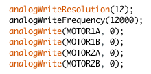
- Screen Shot 2016-07-08 at 5.58.29 PM.png (10.95 KiB) Viewed 992 times
$ grep analogWrite ~/github/Arduino/build/linux/work/lib/keywords.txt
analogWriteFrequency KEYWORD2 AnalogWrite
analogWrite KEYWORD2 AnalogWrite
analogWriteResolution KEYWORD2 AnalogWriteResolution
BTW: energia (msp430/arm port to ti chips) calls it analogFrequency(HZ) and it applies to all pins
i.e they could add the ability to add keyboards to each third party core.
i.e they could add the ability to add keyboards to each third party core.
I think Leaflabs just forgot to write it, or perhaps it was not part of Arduino prior to version 1.0
I recall someone may have now written the code for this, so try searching the forum e.g. via google site:stm32duino.com and see if you can find their code.


