In the hardware.c there is a comment “we do not do it with PC12” (even I saw there was a setPin(C,12) before in the source), maple mini uses PB9 for the disconnect, and Jaromir in his excellent soldering guide is using PB10 – why?
Also I’ve read somewhere we do it via PA12 (D+) today (no external transistor needed).
So where in the sources we can set a pinXY for the usb disconnect (with the external transistor)?
PS: I want to use PB2 (boot1) for that..
BTW, a closer look at the MapleMini 2 transistors disconnect switch reveals there is a nice trick built in – the base of Q2 is powered from USB_5V (VUSB pin on the usb connector) – thus the Q2 cannot toggle the 1k5 resistor when the USB cable is disconnected. The resistor is then floating, for any DISC voltage level. So the circuit is fully off and you can toggle DISC as you wish.
![]()
With the BP’s high-side Q1 pMosfet switch it may work similarly as the MM when the source/emitter of the transistor Q1 will be connected to VUSB (what is not the case when connected to 5V or 3.3V Vcc). So when connected to 3.3Vcc any logic change at the DISC signal will toggle the 1k5 resistor, not good.. ![]()
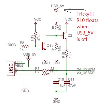
- MM USB Disconnect.JPG (41.23 KiB) Viewed 1598 times
What we do to reset the USB is basically a hack ( but thats the only option unless you change the BP hardware)
the fredbox’s bipolar:
http://www.stm32duino.com/viewtopic.php?t=780
and Jaromir’s pmosfet hack:
http://www.stm32duino.com/viewtopic.php … mos#p12933
A difficult to understand settings and processes with DISC pins, even weird imho ![]()
Basically we have two places where we handle the 1k5 resistor at USB’s D+ :
1. in the bootloader, DISC pin defined in config.h (maples) or in usb.c (generics) – line 40+, DISC used in usb.c
===============================================================================================
– for Maple we: set the DISC pin as OpenDrain, then set it to 1, set it to 0, and that is it..
– for MM it is PB9
– for generic we: set DISC pin as PushPull, then set it to 0, wait about 50 useconds (??), set it to Input (let it float), and that is it..
– for generic it is PA12 (D+)
Signaling based on DISC pin level:
A. MapleMini:
log0: we pull D+ weak high via 1k5
log1: we let the D+ float (1k5 disconnected from Vcc)
B. Generic:
log0: we pull D+ hard low
Input: we let D+ be pulled weak high via 1k5
2. in the core – DISC pin defined in board.h – DISC pin is used for cdc connect and disconnect in usb_serial.cpp – line 60-90
===========================================================================================================
– for MM it is PB9
– for generic it is PB10 (??)
Signaling based on DISC pin level:
A. for MM we pull D+ weak high via 1k5, or, we let the D+ float (1k5 disconnected from Vcc)
B. for generic we pull D+ hard low, or, we let D+ be pulled weak high via 1k5
![]()
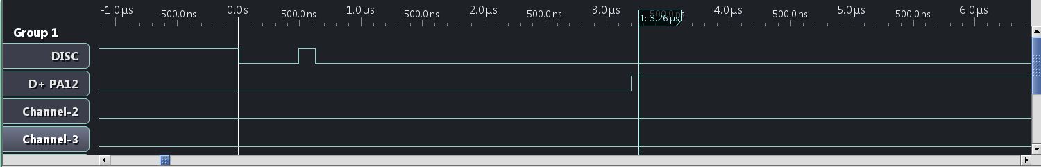
In the sketch, I think MM sets DISC (High) to reset the USB, this pulls D+ to USB (Vdd). MM then leaves DISC set to 1 .
I presume USB DP is pulled low by the host (PC)
The Generic does not have a way to disconnect the 1.5k from Vdd as its permanently pulled high, so the trick is to set the pin as GPIO and drive it LOW, then release the GPIO pin, so that USB DP is pulled high by the 1.5k
The difference between these 2 methods, will be that on the Generic board, as soon as it is plugged in USB DP will be High (on the MM it will initially be Low). After some “setup” time USB DP is driven low and then released.
So there is a delay between the board being connected and USB DP going from Low to High.
I can’t remember what the bootloader does. But I presume it must reset DISC (on MM) to Low, for some time, then set DISC so that USB DP can be pulled high via the transistor.
BTW. I think the USB spec says that USB DP should not be driven low by the target, but we don’t have any choice – and normally it works OK.
1. D+ is pulled “weak” high via the 1k5 resistor to Vcc,
2. D+ is not pulled weak high, D+ does not see the 1k5 resistor (a high impedance), as the 1k5 resistor is disconnected from Vcc.
There are none such DISC pin levels where the D+ could be pulled hard low, weak low, or hard high..
Yes. I suspect using a FET is the best system. I did try to modify a GD32 board to add a P Channel FET for Reset but didnt manage to make it work, however I suspect I had some problem with the clock speed on the GD32 vs the STM32 wen trying to use the MM code in the bootloader
It has got a 100k resistor builtin on the pcb (R4) in series with the signal, but it must not be a problem with a pmosfet (provided we do not talk about 15ns long pulse, the RC of this circuit is about 40usecs).
However, I cannot get it working on PB2.
Built a new bootloader with PB2 and with maple hardware option. It does not find the DFU..yet..
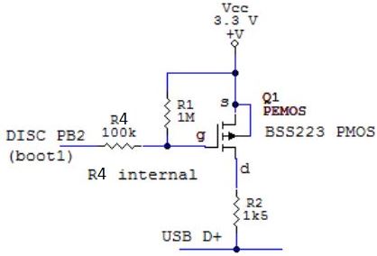
- PB2 disconnect.JPG (12 KiB) Viewed 1571 times
I think I had similar problems, I tried using a P FET to reset the USB on a GD32, but it didnt work.
And I didnt have time to debug the hardware or software.
I still have the GD32 board with the PFET on it, so I will try to look at the waveform’s tomorrow with my oscilloscope to see it I can see why it doesnt work
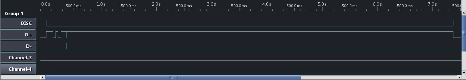
After I press hw reset (during the reset button is pressed down the 1k5 is disconnected):
1. it switches the 1k5 to 3.3V
2. Windows bells and enumerates immediately and in the device manager I see the DFU driver, green LED blinks aprox 3Hz
3. it keeps 1k5 switched to 3.3V for another 8 secs, DFU still in dev manager visible, green LED still blinks
4. after 8 secs it disconnects the 1k5, win bells and the DFU disappears from the dev manager, green LED stops blinking.
Upload from arduino does not work, it cannot find DFU.
![]()
- disc PB12 2.JPG (46.91 KiB) Viewed 784 times
- disc PB12 4.JPG (52.28 KiB) Viewed 782 times
http://www.stm32duino.com/viewtopic.php?t=780
So I flashed his binary in and solder DISC to PB9. Using the PMOS as above. Also edited the board.h.
The led blinks only couple of seconds before it goes to userland, so there is a difference between his and mine source/binary.
No go.
I’ve edited the generics core files where applicable – to remove the PA12 gpio disconnect stuff (hopefully).
No go.
So finally I set MapleMini in the IDE as the board of choice and it works PERFECTLY now. No issues with upload from IDE. ![]()
It seems to me in the current generics –
1. the bootloader source has been changed since December, and
2. also the generics BP core files still include incompabilities with the external disconnect hardware..
Now, how to consolidate all the stuff such we can build a bootloader for BPill (DISC pin as the option) and have working core files for Generic_BP_EXDISC??
![]()
I compiled the bootloader again for PB12 DISC (pmos, 68k from g to Vcc), it enumerates. I set MapleMini profile in IDE (and set PB12 in maple’s /board/board.h).
First attempts it did not find the DFU.
After few plug out/ins during the upload the DFU was found and it uploaded the sketch (maple com appeared).
Afterwards it finds the DFu each time and it uploads the sketch fine.
The only issue I see it keeps the DISC active for 8secs (see the LA traces) so after upload it takes several seconds it ends up (you cannot open serial monitor till the final bell).
The old fredbox version ends immediately after upload – we probably missing to set DISC high somewhere at the end in the latest source.. Or I am not able to compile the bootloader properly..
This is the schematics which works here:
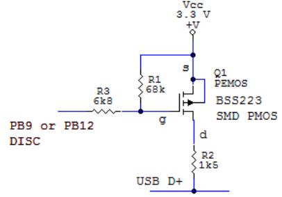
- PMOS DISC.JPG (19.31 KiB) Viewed 764 times
Now it uploads fine. There is still the 8secs issue (the LED indicates for 6secs after the upload finishes it is in bootloader, then bells and goes to userland). MapleMini goes immediately after upload finishes.
So the generic target for BluePill with DISC pin at PB2 may look like this in config.h:
..

#elif defined TARGET_GENERIC_F103_DISC_PB12  // BluePill
#define HAS_MAPLE_HARDWARE 1
#define LED_BANK GPIOC
#define LED_PIN 13
#define LED_ON_STATE 0
#define BUTTON_BANK 1
// DISCONNECT PIN (drives an highside PMOS/PNP)
// mind the DISC pin is configured Open Drain
#define USB_DISC_BANK GPIOB
#define USB_DISC_PIN 2
..
After the mod the USB DISC pin is PB2, Boot0 = 0, the config files mods as above, IDE board generic BPill.
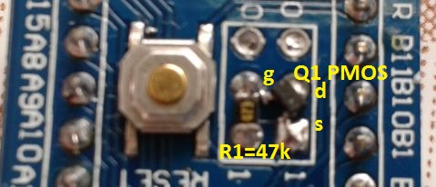
- DISC mod 1.JPG (44.52 KiB) Viewed 708 times
I could not see a FET in the photos.
Can you draw a schematic of these latest changes ( e.g. just draw it on paper and take a photo)
I have got problem with my attachment quota – I deleted almost all pictures from the past and still off the quota:(.
==========================
The schematics is the same as the above PMOS DISC.JPG:
disconnect pin PB2
sch.R3 1k..10k (a good engineering practice is to have one there)
sch.R2 1k5 (must be)
sch.R1 10k..100k (must be)
Q1 – pmosfet with low Vgs trigger voltage (around 1.5V)
or
Q1 – pnp bipolar, any general purpose type
==========================
The actual implementation is depicted on the shots above – on the BPill PCB you mess with pcb.R3, pcb.R4, pcb.R10
Boot0/1 Header – removed
pcb.R4 = sch.R3
pcb.R3 = removed
pcb.R10 = removed
I didnt realise there was a user quota on images.
I will see if I can change it, or perhaps rescale your images ( though I would have to find and download them and upload again)
I don’t know if this is a user quota issue of an overall site quota.
The there is a setting called “Quota” which seems to be set at 52Mb. But I just checked and this seems to be the actual total size of all files rather than being a limit.
I can’t find anything which says there is a limit to the total size of attachments a user can upload, but there is a limit per post I think
https://www.inmotionhosting.com/support … t-settings
Are you sure you can’t attach images to any post ?
The same when I want to add a picture to a new post.
I think I found the setting and I have increased it ![]()
665kB of attachments here.
OK.
I wonder if I need to reset something to get it to notice the change
I’ll get back to you on this one.
