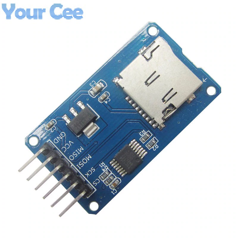
My connections (SD module -> blue pill)
CS -> PA15
SCK -> PB3
MISO-> PB4
MOSI -> PB5
GND->GND
VCC connected to external 5V
SD library’s CardInfo:
/*

SD card test
This example shows how use the utility libraries on which the'
SD library is based in order to get info about your SD card.
Very useful for testing a card when you're not sure whether its working or not.
The circuit:
* SD card attached to SPI bus as follows:
** MOSI - pin 11 on Arduino Uno/Duemilanove/Diecimila
** MISO - pin 12 on Arduino Uno/Duemilanove/Diecimila
** CLK - pin 13 on Arduino Uno/Duemilanove/Diecimila
** CS - depends on your SD card shield or module.
Pin 4 used here for consistency with other Arduino examples
created 28 Mar 2011
by Limor Fried
modified 9 Apr 2012
by Tom Igoe
*/
// include the SD library:
#include <SPI.h>
#include <SD.h>
// set up variables using the SD utility library functions:
Sd2Card card;
SdVolume volume;
SdFile root;
// change this to match your SD shield or module;
// Arduino Ethernet shield: pin 4
// Adafruit SD shields and modules: pin 10
// Sparkfun SD shield: pin 8
const int chipSelect = PA15;
void setup() {
// Open serial communications and wait for port to open:
Serial.begin(9600);
while (!Serial) {
; // wait for serial port to connect. Needed for native USB port only
}
Serial.print("\nInitializing SD card...");
// we'll use the initialization code from the utility libraries
// since we're just testing if the card is working!
if (!card.init(SPI_HALF_SPEED, chipSelect)) {
Serial.println("initialization failed. Things to check:");
Serial.println("* is a card inserted?");
Serial.println("* is your wiring correct?");
Serial.println("* did you change the chipSelect pin to match your shield or module?");
return;
} else {
Serial.println("Wiring is correct and a card is present.");
}
// print the type of card
Serial.print("\nCard type: ");
switch (card.type()) {
case SD_CARD_TYPE_SD1:
Serial.println("SD1");
break;
case SD_CARD_TYPE_SD2:
Serial.println("SD2");
break;
case SD_CARD_TYPE_SDHC:
Serial.println("SDHC");
break;
default:
Serial.println("Unknown");
}
// Now we will try to open the 'volume'/'partition' - it should be FAT16 or FAT32
if (!volume.init(card)) {
Serial.println("Could not find FAT16/FAT32 partition.\nMake sure you've formatted the card");
return;
}
// print the type and size of the first FAT-type volume
uint32_t volumesize;
Serial.print("\nVolume type is FAT");
Serial.println(volume.fatType(), DEC);
Serial.println();
volumesize = volume.blocksPerCluster(); // clusters are collections of blocks
volumesize *= volume.clusterCount(); // we'll have a lot of clusters
volumesize *= 512; // SD card blocks are always 512 bytes
Serial.print("Volume size (bytes): ");
Serial.println(volumesize);
Serial.print("Volume size (Kbytes): ");
volumesize /= 1024;
Serial.println(volumesize);
Serial.print("Volume size (Mbytes): ");
volumesize /= 1024;
Serial.println(volumesize);
Serial.println("\nFiles found on the card (name, date and size in bytes): ");
root.openRoot(volume);
// list all files in the card with date and size
root.ls(LS_R | LS_DATE | LS_SIZE);
}
void loop(void) {
}
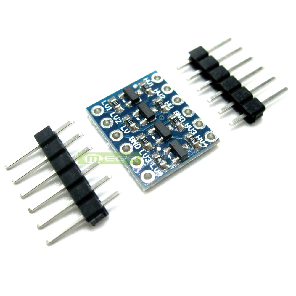
It may not work with 3.3V STM32 hardware, as the level converter is not required (and most likely will cause incorrect voltage levels to be sent to the SD Card)
http://www.ebay.com/sch/i.html?_from=R4 … duino+3.3v
In the mean time I want to start experimenting with SD. I’ve tried using a logic level converter for the SPI lines between the STM32F103 and SD module, however results are also disappointing (maybe the level converter is too slow?). Is there no way to get started with the SD module I currently have?
what may be attempted though is start with low spi clock speeds
it seem those 3.3v tf micro-sd adaptors less those series resistors are ‘hard to find’ on ebay, a lot of them put series resistors or some level translators and labled that 3.3v/5v. but i think this impact the performance for 3.3v ones once you raise the spi clock to mhz ranges, but that’s where we want to operate, otherwise you may end up with transfer speeds say in the low hundreds kbytes/s possibly <100kbytes/s at best
what i did is i removed 3 series resistors (replaced with wires) on my ili9341 lcd with a sd adapter and used that adaptor
http://www.stm32duino.com/viewtopic.php?f=44&t=2026
note that your adapter seem to be using a buffer/transceiver IC, i think buffer ICs should still work for the data lines.
but if you want to power the card, you may want to try to find a 5v voltage source if you want to connect before the LDO
if you make do with 3.3v across the LDO, the dropout is likely to be at least 0.5v (leaving 2.7v) or some cases 1v (leaving 2.2v)
but do be careful about putting a 5V VCC as that could possibly damage STM32F1 chip and or SD if done incorrectly, SPI 1 on stm32f103 is on analog pins which is not 5V tolerant
You could try unsoldering the level converter and carefully soldering the inputs to the outputs for MOSI and SCLK.
But as @ag123 said, there may also be problems with the regulator, so make sure you supply it with 5V or alternatively connect the 3.3V to the output of the voltage regulator.
You may need to remove in the voltage regulator as well, but in my experience, the ones I’ve used, do not seem to draw current in through their output if supplied with 3.3V
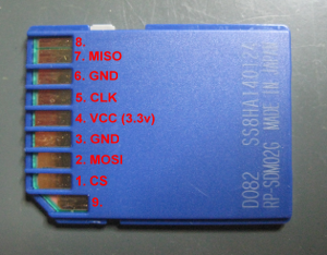
It seems at least some modifications is required to my current SD module, however if possible I’d like to stray away from SMD soldering ![]() Would some header pins soldered directly to the pins of a microSD-to-SD adapter work instead? I’ve looked up the pins from an SD card, seems like there are SPI lines available and are 3.3V tolerant. I went ahead and soldered some header pins to the microSD adapter.(not my picture but looks very similar) I’ve put the SD module aside and connected the SD card directly to the microcontroller board.
Would some header pins soldered directly to the pins of a microSD-to-SD adapter work instead? I’ve looked up the pins from an SD card, seems like there are SPI lines available and are 3.3V tolerant. I went ahead and soldered some header pins to the microSD adapter.(not my picture but looks very similar) I’ve put the SD module aside and connected the SD card directly to the microcontroller board.
Communication with an 3.3V arduino pro mini works fine! Both library outputs correct information about the inserted SD card and lists all files on the storage card.
On the STM32f103 it at least recognizes an SD card, however it is still running into troubles (correct card size 8GB);
SD library’s CardInfo.ino serial output (code in opening post):
ializing SD card...Wiring is correct and a card is present.
Card type: SD2
Could not find FAT16/FAT32 partition.
Make sure you've formatted the card
It seems that the read data is mostly 0x00, so there still must be something wrong there.
It seems that the read data is mostly 0x00, so there still must be something wrong there.
Also try to exchange MOSI/MISO pins..
you may like to try to route a 5V pin from your bluepill to the VCC pin on the SD breakout board
*warning*, when doing all these, have voltmeter handy. after connecting 5V VCC my guess is first measure voltages off the msoi, mosi, sck, cs pins on the breakout before even connecting it to bluepill since SPI 1 is not 5V tolerant
you would probably need to measure voltages on blue pill e.g. the 5V pin which seemed to be pin 3 to ascertain that it is the correct pin
the schematics are in the stm32duino forum wiki
http://wiki.stm32duino.com/index.php?title=Blue_Pill
http://www.stm32duino.com/viewtopic.php?f=13&t=20
https://github.com/greiman/SdFat
in addition, i actually used the SPI.cpp, SPI.h ‘drivers’ in libraries/SPI
https://github.com/rogerclarkmelbourne/ … raries/SPI
you could use the sd fat libraries that you are familiar with, but i’d guess you would need to check where they are hooked into SPI.h.
i like to copy SPI.c, SPI.h from libraries/SPI and put that in the same folder as the sketch and update the codes to include “SPI.h” rather than <SPI.h>. there seem to be some codes in the libmaple core dealing with spi. i copied the files and place it in the same folder to avoid possibly including the incorrect libraries from the libmaple core
these pins looks a little strange to me as well
CS -> PA15
SCK -> PB3
MISO-> PB4
MOSI -> PB5
GND->GND
SPI1 is normally on
PA4 - SS (you could use this as /CS if you'd like)

PA5 - SCK1

PA6 - MISO1

PA7 - MOSI1
[ag123 – Fri May 26, 2017 7:25 pm] –
SPI1 is normally on
PA4 - SS (you could use this as /CS if you'd like)

PA5 - SCK1

PA6 - MISO1

PA7 - MOSI1
I ran into similar trouble, and in my case the problem was that the SD card reader did not work at 3.3V (although the specs said so). Once I powered it with 5V, instead, it started to work just fine (using the “default” Arduino SD library, too).
Note that when powering with 5V, you will want to make sure to either use a logic level converter, or connect to SPI2 (pins PB12-PB15, which are designated as 5V tolerant). Use SPI.setModule(2);
But perhaps that is fast enough for SD
[tfried – Sat Dec 30, 2017 8:21 pm] –
Not to revive a dead thread, but for those searching for the same problem:I ran into similar trouble, and in my case the problem was that the SD card reader did not work at 3.3V (although the specs said so). Once I powered it with 5V, instead, it started to work just fine (using the “default” Arduino SD library, too).
…
I have yet to find an SD card reader that is not 3.3V … I have received card readers that have a 3.3 Volt regulator for 5V input to Vcc. In this case, one just shorts the regulator. Often, the 5V cards have resistors in series with signal lines to provide a quasi-voltage divider … a poor one. These resistors can be removed and 0-Ohm SMD units installed or just wire jumpers. The only pin that you may wish to keep a resistor on is the SD-card insertion switch.
Performance on 5V cards is just a wee bit better than lousy. .. the inserted resistance causes timing issues with stray capacitance and inductance.
Ray
I have achieved to make it working with the solution of using “SPI.setModule(2);” It even works with “SPI_FULL_SPEED”
Sincerely.
Pierre
Those 10k on the board (103) are pull-ups, not “limitation resistors”.. Use with 3.3V only !!
[Pito – Thu Mar 22, 2018 8:02 pm] –
I have a 3.3 V µSD card reader like this one (without any regulator, just limitation resistors)
Those 10k on the board (103) are pull-ups, not “limitation resistors”.. Use with 3.3V only !!
You are rigth.
Not intentionnaly, I have connected this SD card with 5 V … it is always alive !
Sincerely.
Pierre
![[Pending Enhancement] RTC values resetting](https://sparklogic.ru/wp-content/uploads/2019/11/nucleo-l476rg-zestaw-startowy-z-mikrokontrolerem-z-rodziny-stm32-stm32l476-90x90.jpg)