It is eliminating two op amp.
How to make this code to make working for any signal amplitude, wchich is the purpose of zero crossing detector ?
Another words how to get the pulse at 1/2 amplitude of applayed signal ?
//unsigned long time;

const int buttonPin = PA7;

void setup() {

pinMode(PB1, OUTPUT);

pinMode(buttonPin, INPUT_PULLDOWN);

//pinMode(buttonPin, INPUT_PULLUP);

}

void loop() {
if (digitalRead(buttonPin) == HIGH)
{
while (digitalRead(buttonPin) == HIGH) {
}
digitalWrite(PB1, HIGH);
//delay micros(50);
delayMicroseconds(100);
//delay(1000);
digitalWrite(PB1, LOW);
delayMicroseconds(100);
}
}
The “zero crossing” means you get from positive to negative (or vice versa) where the “negative” means negative against “ground”.
You do not have hardware in STM32 handy which can work with negative voltages against ground.
That will work for another fixed amplitude only, so detector will be still amplitude dependent.
I can add a voltmeter to code which wil measure amplitude then I will know the value 1/2 of it, wchich give the triggering point.
I know how to add meter, but dont know how to inplement triggering point.
Or use a peak detector as triggering point ?
The simple opto isolated circuits show above should work very well in most real world situations.
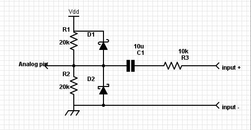
- Screenshot_2018-06-19_16-39-29.png (10.74 KiB) Viewed 818 times
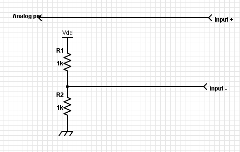
- Screenshot_2018-06-19_17-03-28.png (7.03 KiB) Viewed 812 times
I know that, the problem is with modification of the code not in electronics.
In most cases, however, a resistor plus a zener would do the job.
Can someone help me to find mistake ?
const int sampleWindow = 250; // Sample window width in mS (250 mS = 4Hz)

unsigned int knock;

//int ledPin = 13;

/////////////////////

int ledPin = PB1;

/////////////////////

void setup()

{

Serial.begin(9600);

pinMode(ledPin, OUTPUT);

}
void loop()

{

unsigned long start= millis();  // Start of sample window

unsigned int peakToPeak = 0;   // peak-to-peak level
unsigned int signalMax = 0;

unsigned int signalMin = 1024;
// collect data for 250 miliseconds

while (millis() - start < sampleWindow)

{

//////////////////////////////////

// knock = analogRead(0);

knock = analogRead(PA7);

/////////////////////

if (knock < 1024)  //This is the max of the 10-bit ADC so this loop will include all readings

{

if (knock > signalMax)

{

signalMax = knock;  // save just the max levels

}

else if (knock < signalMin)

{

signalMin = knock;  // save just the min levels

}

}

}

peakToPeak = signalMax - signalMin;  // max - min = peak-peak amplitude

double volts = (peakToPeak * 3.3) / 1024;  // convert to volts
Serial.println(volts);

if (volts >=1.0)

{

//turn on LED

digitalWrite(ledPin, HIGH);

delay(500);

Serial.println("Knock Knock");

}

else

{

//turn LED off

digitalWrite(ledPin, LOW);

}

}
Replace every occurrence of ‘1024’ with ‘4096’ and it may work?
//Replace every occurrence of '1024' with '4096' and it may work?

//http://stm32duino.com/viewtopic.php?f=19&t=3778&start=10
const int sampleWindow = 250; // Sample window width in mS (250 mS = 4Hz)

unsigned int knock;

//int ledPin = 13;

/////////////////////

int ledPin = PB1;

int analog  = PA7;

/////////////////////

void setup()

{

Serial.begin(9600);

pinMode(ledPin, OUTPUT);

}
void loop()

{

unsigned long start= millis();  // Start of sample window

unsigned int peakToPeak = 0;   // peak-to-peak level
unsigned int signalMax = 0;

unsigned int signalMin = 1024;
// collect data for 250 miliseconds

while (millis() - start < sampleWindow)

{

//////////////////////////////////

// knock = analogRead(0);

knock = analogRead(PA7);

/////////////////////

// if (knock < 1024)  //This is the max of the 10-bit ADC so this loop will include all readings

if (knock < 4096)  //This is the max of the 10-bit ADC so this loop will include all readings

{

if (knock > signalMax)

{

signalMax = knock;  // save just the max levels

}

else if (knock < signalMin)

{

signalMin = knock;  // save just the min levels

}

}

}

peakToPeak = signalMax - signalMin;  // max - min = peak-peak amplitude

// double volts = (peakToPeak * 3.3) / 1024;  // convert to volts

double volts = (peakToPeak * 3.3) / 4096;  // convert to volts
Serial.println(volts);

if (volts >=1.0)

{

//turn on LED

digitalWrite(ledPin, HIGH);

delay(5);

Serial.println("Knock Knock");

}

else

{

//turn LED off

digitalWrite(ledPin, LOW);

}

}
Just search for the open energy project
Aka emonlib
Works perfectly on STM32 I have at least multiple people using boards I built which are monitoring power and power factor etc
![[Pending Enhancement] RTC values resetting](https://sparklogic.ru/wp-content/uploads/2019/11/nucleo-l476rg-zestaw-startowy-z-mikrokontrolerem-z-rodziny-stm32-stm32l476-90x90.jpg)