I finally managed to bring the SDIO files in an acceptable form to be published.
It works with 24MHz clock and 4bits wide bus, and tested only for the generic F407VET6 board.
I have committed 2 files to libmaple core directory, and 2 files to a new SDIO lib under STM32F4/libraries.
Usage:
– get the master branch from my repo
– get the SdFat lib from https://github.com/greiman/SdFat
– insert into line 164 of SdFatConfig:
#elif defined(__STM32F4__)

#define ENABLE_SDIO_CLASS 1
When I have enough time, I will pull you F4 changes
If not, please post here any problems.
Thank YOU very much for YOUR work !
[RogerClark – Sun Jun 18, 2017 9:31 pm] –
ThanksWhen I have enough time, I will pull you F4 changes
I have to first merge the latest commits from your master to my branch, I hope I manage it today in the evening.
I’ll let you know.
[stevestrong – Mon Jun 19, 2017 9:13 am] –[RogerClark – Sun Jun 18, 2017 9:31 pm] –
ThanksWhen I have enough time, I will pull you F4 changes
I have to first merge the latest commits from your master to my branch, I hope I manage it today in the evening.
I’ll let you know.
OK
I think it may be OK without doing this.
But don’t rush, I have so many other things I need to do.
Use a freshly formatted SD for best performance.
Type any character to start

#################################################

Opening the read file..

Opening the write file..

Reading and Writing..

*************************************************

Done in 24063 msecs

*************************************************

Running CRC calculations...

File in CRC:  22BCDBEC

File out CRC: 22BCDBEC

*************************************************

Done in 70620 msecs
Type any character to start

#################################################

Opening the read file..

Opening the write file..

Reading and Writing..

*************************************************

Done in 34167 msecs

*************************************************

Running CRC calculations...

File in CRC:  22BCDBEC

File out CRC: 22BCDBEC

*************************************************

Done in 70937 msecs
Type any character to start

#################################################

Opening the read file..

Opening the write file..

Reading and Writing..

*************************************************

Done in 37755 msecs

*************************************************

Running CRC calculations...

File in CRC:  22BCDBEC

File out CRC: 22BCDBEC

*************************************************

Done in 70910 msecs
Type any character to start

#################################################

Opening the read file..

Opening the write file..

Reading and Writing..

*************************************************

Done in 36741 msecs

*************************************************

Running CRC calculations...

File in CRC:  22BCDBEC

File out CRC: 22BCDBEC

*************************************************

Done in 70734 msecs
Type any character to start
I get with my:
Use a freshly formatted SD for best performance.

Type any character to start
*************************************************
Opening the read file..
Opening the write file..
Reading and Writing..
*************************************************
Done in 61039 msecs
*************************************************
Running CRC calculations...
File in CRC: DE9D6BE7
File out CRC: DE9D6BE7
*************************************************
Done in 71259 msecsType any character to start
*************************************************
Opening the read file..
Opening the write file..
Reading and Writing..
*************************************************
Done in 60230 msecs
*************************************************
Running CRC calculations...
File in CRC: DE9D6BE7
File out CRC: DE9D6BE7
*************************************************
Done in 71251 msecsType any character to start
*************************************************
Opening the read file..
Opening the write file..
Reading and Writing..
For libmaple core, the first read and write takes a lot less time (34231 msecs) than the following read writes (58237 msecs).
Your core seems not to show this issue.
Hmmm.
The Sdcard is not a ramdisk, it lives its own life. When the Arm (or accelerated 8051) inside the Sdcard decides to do some housekeeping, your write time will be longer.
So it is not due different write latencies.
[danieleff – Wed Jun 21, 2017 5:03 am] –
100MB F407
I get with my:
Use a freshly formatted SD for best performance.

Type any character to start
*************************************************
Opening the read file..
Opening the write file..
Reading and Writing..
*************************************************
Done in 61039 msecs
*************************************************
Running CRC calculations...
File in CRC: DE9D6BE7
File out CRC: DE9D6BE7
*************************************************
Done in 71259 msecsType any character to start*************************************************
Opening the read file..
Opening the write file..
Reading and Writing..
*************************************************
Done in 60230 msecs
*************************************************
Running CRC calculations...
File in CRC: DE9D6BE7
File out CRC: DE9D6BE7
*************************************************
Done in 71251 msecsType any character to start*************************************************
Opening the read file..
Opening the write file..
Reading and Writing..
this is SDIO, not SPI.
And higher frequencies than 37MHz for SDIO (tested by Pito) do not work reliable anymore. This is a HW limitation of the F4 chip.
[stevestrong – Thu Jun 22, 2017 5:49 pm] –
Vitor,
this is SDIO, not SPI.
And higher frequencies than 37MHz for SDIO (tested by Pito) do not work reliable anymore. This is a HW limitation of the F4 chip.
		while ( i-- ) { // do 8 byte copies, is much faster than single byte copy

*dst++ = *src++; *dst++ = *src++; *dst++ = *src++; *dst++ = *src++;

*dst++ = *src++; *dst++ = *src++; *dst++ = *src++; *dst++ = *src++;

}
[vitor_boss – Fri Jun 23, 2017 2:20 pm] –
Isn’t possible to work with full register(32bits) on those lines?
Not in this case.
The byte-wise copying is performed when the passed buffer address is not word (uint32_t) aligned.
#include <SPI.h>

#include <Arduino.h>

#include "SdioF4.h"
SdFile myFile;

SdFat sd;
void setup(void) {

Serial.begin(115200);

//while ( !Serial.isConnected() ) ;
if (!myFile.open("test.txt", O_RDWR | O_CREAT | O_AT_END))

{

sd.errorHalt("Error open file !");

}

else

{

myFile.print("TEST");

myFile.close();

}

}
void loop(void)

{

//

}
You still have to insert into line 164 of SdFatConfig:
#elif defined(__STM32F4__)

#define ENABLE_SDIO_CLASS 1
- SdFatConfig.h
- (7.03 KiB) Downloaded 174 times
Thank you
using the demo code, it says
"/home/stephen/.arduino15/packages/arduino/tools/arm-none-eabi-gcc/4.8.3-2014q1/bin/arm-none-eabi-g++" -c -g -Os -w  -std=gnu++11 -ffunction-sections -fdata-sections -nostdlib --param max-inline-insns-single=500 -fno-rtti -fno-exceptions -DBOARD_generic_f407v -DVECT_TAB_BASE -DERROR_LED_PORT=GPIOA -DERROR_LED_PIN=7 -w -x c++ -E -CC -mcpu=cortex-m4 -DF_CPU=168000000L -DARDUINO=10803 -DARDUINO_STM32GenericF407VET6 -DARDUINO_ARCH_STM32F4  -mthumb -DSTM32_HIGH_DENSITY -DSTM32F4 -DBOARD_generic_f407v -DUSB_NC  -mthumb -D__STM32F4__ "-I/home/stephen/sketchbook/hardware/ss-Arduino_STM32/STM32F4/system/libmaple" "-I/home/stephen/sketchbook/hardware/ss-Arduino_STM32/STM32F4/cores/maple/libmaple/usbF4" "-I/home/stephen/sketchbook/hardware/ss-Arduino_STM32/STM32F4/cores/maple" "-I/home/stephen/sketchbook/hardware/ss-Arduino_STM32/STM32F4/variants/generic_f407v" "-I/home/stephen/sketchbook/hardware/ss-Arduino_STM32/STM32F4/libraries/SDIO" "-I/home/stephen/sketchbook/libraries/SdFat/src" "-I/home/stephen/sketchbook/hardware/ss-Arduino_STM32/STM32F4/libraries/SPI/src" "/home/stephen/sketchbook/hardware/ss-Arduino_STM32/STM32F4/libraries/SDIO/SdioF4.cpp" -o "/tmp/arduino_build_711891/preproc/ctags_target_for_gcc_minus_e.cpp"

/home/stephen/sketchbook/hardware/ss-Arduino_STM32/STM32F4/libraries/SDIO/SdioF4.cpp:22:27: fatal error: libmaple\sdio.h: No such file or directory

#include <libmaple\sdio.h>
https://github.com/stevstrong/Arduino_S … e/libmaple
Please check that you have this folder and the files.
i think it shouldn’t make any difference.
i changed it anyway, it’s now a directory.
~/sketchbook/hardware/ss-Arduino_STM32/STM32F4/cores/maple/libmaple$ ll sdi*

-rw-r--r-- 1 stephen stephen  5384 Jun 20 20:03 sdio.c

-rw-r--r-- 1 stephen stephen 13451 Jun 20 20:03 sdio.h
Since the path “/cores/maple” is included to the compile/build process, it should theoretically be able to include any file from the subdirectory “/libmaple/” when having an absolute reference thereto…
Is it maybe a “/” vs. “\” issue?
the other one i ‘m having fun with is I2CScanner, (but it has worked) Wire.h not found
just tried with yours as the only Arduino_STM directory, still the same
fresh copy coming up
curiously only the SDIO files have the backslash, the other libraries are forward slashes.
30min later, there are a lot of usb associated files full of the little bleeps
###########################################################
went slightly mad with a recursive find/replace on *.cpp, *.c, *.h, *.html, Makefile, Doxyfile
only really saw your SDIO dir changed.
anyone, i found myself setting in chrismicro repo, board as Black F407VE with SDIODirListWriteRead.ino
it works ![]()
![]()
stephen
libmaple/sdio.h
libmaple/dma.h
i think i was surprised i think in the cores libmaple directory, nothing
finally it compiles and links, that’s my blink_millis sketch
I2CScanner still can’t find Wire.h
srp
You could copy/paste from F1 lib directory and test, maybe it works out of the box
If it does not work, please open a separates thread for that.
not implemented would certainly be an explanation. ![]()
stephen
ss-Arduino_STM32 is my backslash edited version.
stephen
Did the backslash replacement in “SDIOF4.cpp” solve your problem?
Makes sense to replace all other include path backslashes in the repo?
that diff should be enough to give all the ones i changed; there may well be more.
in the libmaple dir, i think sdio.[cpp|h] was it.
whether or not it makes sense is really down to how windows behaves with forward slashes.
as most of the grep’d ‘#include’ lines showed forward slashes, it may be much more tolerant of them than linux !
not often there’s such a positive for windows.
stephen
Please take the master branch, the generic one does not exists anymore.
I know now why I included backslashes: because Github for windows also uses it:
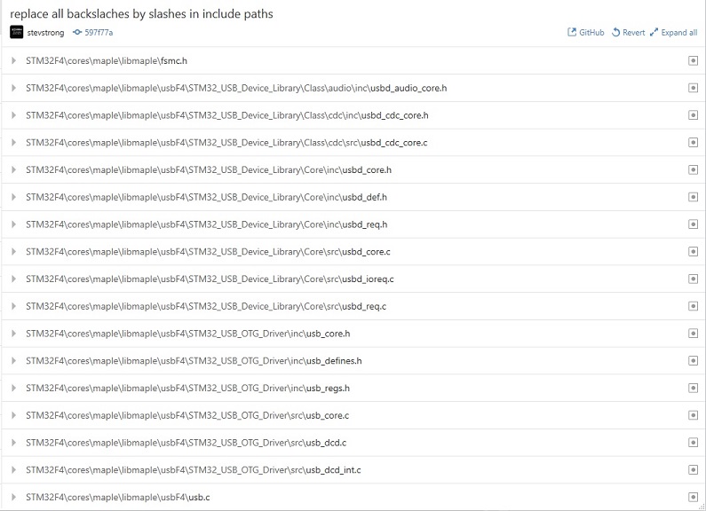
- github_backslashes.jpg (115.64 KiB) Viewed 280 times
yep, noticed that
pulling it now
i’m using a Black F407VE and declaring generic_f407v as the board type.
all the sketches that i’ve tried (SdioDemo is one) are reporting SdFat.h not found.
i mention this as it’s the only one having SdioF4 explicitly declared
//#include <SdFat.h>

#include <SdioF4.h>
I dont know under linux how Arduino ide handles the paths, the /libraries folder should be included there, so that SdFat.h is found.
An example sketch is at the end of page 2.
now compiles, i edited to use a SERIALDEV from a define, easier to change just one
running a mite different, i tried with Serial, Serial1, but only with SerialUSB i got any output.
evidently it also doesn’t like my Kingston SDC4/4GB sdcard
size,write,read

bytes,KB/sec,KB/sec

512,145.39,680.11

1024,227.14,839.41

2048,344.94,1623.80

4096,file.write returned: 4294967295

error: write failed

SD errorCode: 0X60,0X0
If so, then it can be a card issue, maybe it does not support the amount of data to be transferred at once.
PLL_Q set to 14. You would need Serial1 as the USB will stop working.
[Pito – Wed Jul 05, 2017 9:11 am] –
Try 12MHz SDIO clock with the CL4 card..
PLL_Q set to 14. You would need Serial1 as the USB will stop working.
Before doing this I have to be sure that it is really the frequency which causes the problem, and not any other card-intern related issue.
If 2kB buffer works OK at 24MHz, why shouldn’t 4kB buffer work as well?
Who does say that?
Also do not use SdFat-beta but the latest SdFat master https://github.com/greiman/SdFat
There is maybe a fix (see my post) already implemented as the SdFat got problem with file.write() with buffer sizes above 128kB.
You suggested to decrease the SDIO frequency for CL4 cards. And I do not see (yet) any reason for that, because from stephen’s log obviously 2kB buffer works well @24MHz, it only generates 0x60 (SD_CARD_ERROR_DMA) error when using 4kB buffer. That’s why I asked for more information from stephen, to understand and localize the issue.
So you do refer this, right?
2048,344.94,1623.80

4096,file.write returned: 4294967295

error: write failed

SD errorCode: 0X60,0X0steve – oh thank you for this and anyone else
what extra info do you want from me ?
changed the card from a whatever 4gb to 8gb, labelled ultra, 2 colour, red & silver, with a 1 inside a U
how high do you want to go, try 16G, 32G ? couple or three of those.
sdformat – if that’s the official one, i don’t think it’s a linux port, dd +fdisk+mkfs.vfat is best i’ve got.
typical, win+mac
i’ll go looking though.
Type any character to start.
size,write,read
bytes,KB/sec,KB/sec
512,321.57,1078.55
1024,738.05,2124.35
2048,1250.39,3516.35
4096,2070.08,5286.28
8192,2439.10,5278.28
16384,2424.50,5270.61
32768,2356.58,5282.14
totalMicros 79140057
yieldMicros 46090617
yieldCalls 67753
yieldMaxUsec 193440
kHzSdClk 24000
Done
I wanted to know whether successive test with the same card, which showed the error, will show similar/identical error on the following test as well.
[zmemw16 – Wed Jul 05, 2017 11:20 am] –
in fsmc.h i see ‘See ../notes/fsmc.txt for more info’
is this a hang over from original sources or yours ?
That is just part of original source.
Further supported features and development status can be found here: viewtopic.php?f=39&t=1976
(yes, FSMC for 16bit parallel LCDs works already ![]() )
)
The official (Roger’s) repo is also almost up to date with my one.
@Pito
[Pito – Wed Jul 05, 2017 9:57 am] – and also set the SDIO gpio’s output driver strength to MEDIUM!
Nope, this libmaple SDIO lib works (at least for my CL10 card on generic black F407VET board) @24MHz only if the SDIO pins are set to output PP + PU at HIGH (50MHz) frequency.
I tried with MEDIUM strength and got errors at the very first card access after switching the SDIO clk from 400kHz to 24MHz…
Pito wrote:Also Serial1 is something you would need handy, definitely..
Interestingly all my CL10 cards work @24-44MHz SDIO only with MEDIUM (Black 407ZET, STM32GENERIC)
So maybe there is a subtle difference in card’s inits in the cores somewhere
[Pito – Wed Jul 05, 2017 1:15 pm] –
So maybe there is a subtle difference in card’s inits in the cores somewhere
I would rather think on any difference in the F4 register settings, or any hardware issue, power supply decoupling.
Would a register dump make sense to find out the diff? Is there any reg-dumping sketch available?
Type any character to start.

size,write,read

bytes,KB/sec,KB/sec

512,149.78,695.32

1024,227.49,840.88

2048,348.16,1633.62

4096,file.write returned: 4294967295
Type any character to start.

size,write,read

bytes,KB/sec,KB/sec

512,145.10,678.64

1024,224.82,847.31

2048,352.94,1664.60

4096,file.write returned: 4294967295
Type any character to start.

size,write,read

bytes,KB/sec,KB/sec

512,147.60,695.28

1024,231.63,872.22

2048,369.86,1719.74

4096,511.46,3556.26

8192,504.41,3560.83

16384,504.36,3562.77

32768,504.39,3569.58
totalMicros  218005614

yieldMicros  197107630

yieldCalls   60881

yieldMaxUsec 138343

kHzSdClk     24000

Done
Type any character to start.

size,write,read

bytes,KB/sec,KB/sec

512,147.33,695.80

1024,231.72,866.54

2048,369.51,1732.84

4096,511.83,3561.75

8192,504.74,3565.14

16384,504.56,3563.90

32768,504.45,3560.40
totalMicros  218100065

yieldMicros  200466135

yieldCalls   60934

yieldMaxUsec 146788

kHzSdClk     24000

Done
Type any character to start.

size,write,read

bytes,KB/sec,KB/sec

512,147.35,694.99

1024,231.79,867.61

2048,369.98,1727.27

4096,512.14,3564.36

8192,504.50,3568.53

16384,504.86,3557.19

32768,504.43,3563.17
totalMicros  218056619

yieldMicros  200422778

yieldCalls   60902

yieldMaxUsec 136086

kHzSdClk     24000

Done
Type any character to start.

size,write,read

bytes,KB/sec,KB/sec

512,147.39,695.88

1024,231.84,865.06

2048,369.89,1729.93

4096,512.36,3560.81

8192,504.73,3560.76

16384,504.18,3524.25

32768,504.84,3522.68
totalMicros  218097836

yieldMicros  200400149

yieldCalls   60909

yieldMaxUsec 145093

kHzSdClk     24000

Done
[stevestrong – Wed Jul 05, 2017 1:23 pm] –[Pito – Wed Jul 05, 2017 1:15 pm] –
So maybe there is a subtle difference in card’s inits in the cores somewhereI would rather think on any difference in the F4 register settings, or any hardware issue, power supply decoupling.
Would a register dump make sense to find out the diff? Is there any reg-dumping sketch available?
I think Black’s 407VET and 407ZET boards are from the HW point almost identical, on my board I replaced the 100nF sdcard decoupling capacitor with 2x10u ceramic multilayer with no visible impact.
The F4 registers are set by sdcard’s inits() so the diff has to be in sources somewhere.. Or, do you mean there is a difference in F4VET vs. F4ZET silicon ?
@stephen: except your temperature dependency it seems to me your write speed is suspiciously low – should be close to read speed.
[zmemw16 – Wed Jul 05, 2017 1:25 pm] –
i returned to the 4gb card, there is a press reset after each of the fails, surprisingly it seems to work after a warm up
Is it maybe a power supply stability issue?
I power my board over USB, via a USB-hub, I sometimes use for the USB hub an extra power adapter.
Pito wrote:The F4 registers are set by sdcard’s inits() so the diff has to be in sources somewhere..
The only difference is the chip and maybe +/- 1-3cm in SDIO’s signal wires length.
The same vendor, similar layout..
My board: http://www.stm32duino.com/viewtopic.php … =30#p22456
PS: why the write speed in above benchmark is 1/7 of the read speed?
4096,512.36,3560.81

8192,504.73,3560.76

16384,504.18,3524.25

32768,504.84,3522.68
[Pito – Wed Jul 05, 2017 2:01 pm] –
PS: why the write speed in above benchmark is 1/7 of the read speed?
4096,512.36,3560.81

8192,504.73,3560.76

16384,504.18,3524.25

32768,504.84,3522.68
although just about everything hangs off the hub, ols,2x usb serial, stlink and the board.
stephen
The results today are similar to what I have measured that time (SanDisk Ultra 16GB CL10 card)
Type any character to start.
size,write,read

bytes,KB/sec,KB/sec

512,352.13,1855.96

1024,615.75,2573.66

2048,1273.42,3993.01

4096,3232.87,6568.02

8192,5171.66,8589.67

16384,6754.45,9880.24

32768,8231.03,10657.71
totalMicros  64281101

yieldMicros  44535132

yieldCalls   53279

yieldMaxUsec 134928

kHzSdClk     24000

Done
Type any character to start.
size,write,read

bytes,KB/sec,KB/sec

512,430.66,2197.68

1024,684.68,2444.70

2048,1424.19,4174.99

4096,3339.52,6118.28

8192,5012.46,8629.27

16384,6870.03,9874.56

32768,8144.14,10624.18
totalMicros  57296702

yieldMicros  38051319

yieldCalls   51383

yieldMaxUsec 116471

kHzSdClk     24000

Done
Samsung EVO CL10 8GB
SdFatSdio uses a traditional DMA SDIO implementation.
Type any character to start.
size,write,read

bytes,KB/sec,KB/sec

512,268.75,1186.61

1024,578.31,2013.27

2048,902.17,3499.82

4096,2799.68,5325.05

8192,4729.74,7705.77

16384,7165.14,9325.13

32768,8636.38,10346.14
totalMicros  79935842

yieldMicros  56356622

yieldCalls   114859

yieldMaxUsec 199834

kHzSdClk     24000

Done
Type any character to start.
Additionally I added to monitor log info about the SD card.
And, as requested, the user gets warned about the time to wait.
######################################################

This sketch demonstrates STM32F4 SDIO (DMA) implementation.

######################################################
init time: 7 ms
Card type: SDHC
Manufacturer ID: 2

OEM ID: TM

Product: SA04G

Version: 0.6

Serial number: 289b4188

Manufacturing date: 3/2011
cardSize: 3951.03 MB (MB = 1,000,000 bytes)

flashEraseSize: 128 blocks

eraseSingleBlock: true

OCR: c0ff8000
Volume is FAT32

blocksPerCluster: 64

clusterCount: 120320

freeClusters: 120193

freeSpace: 3938.48 MB (MB = 1,000,000 bytes)

fatStartBlock: 14502

fatCount: 2

blocksPerFat: 941

rootDirStart: 2

dataStartBlock: 16384
FreeStack: 84095

######################################################
Type any character to start
Test started - please wait, it may take up to 3 minutes
size, write, read

bytes, KB/sec, KB/sec

512,
Kingston CL4 4GB
Test started - please wait, it may take up to 3 minutes :)
size, write, read
bytes, KB/sec, KB/sec
512, 45.45, 482.42 in T=00:03:15
1024, 24.92, 693.02 in T=00:06:05
2048, 25.21, 1286.25 in T=00:15:00
4096, 1337.13, 2271.51
8192, 1702.51, 3916.33
16384, 3012.27, 5492.42
32768, 3638.46, 7413.43 in T=00:15:20
totalMicros 914714129 => 15.5minutes
yieldMicros 867872714
yieldCalls 84774
yieldMaxUsec 150782
kHzSdClk 24000
Done
Type any character to start
######################################################

Demo sketch of STM32F4 SDIO (DMA) implementation.

######################################################
init time: 8 ms
Card type: SD2
Manufacturer ID: 27

OEM ID: PH

Product: SD02G

Version: 3.0

Serial number: 97bdbf7c

Manufacturing date: 8/2011
cardSize: 1969.23 MB (MB = 1,000,000 bytes)

flashEraseSize: 128 blocks

eraseSingleBlock: true

OCR: 80ff8000
Volume is FAT16

blocksPerCluster: 64

clusterCount: 60086

freeClusters: 59578

freeSpace: 1952.25 MB (MB = 1,000,000 bytes)

fatStartBlock: 138

fatCount: 2

blocksPerFat: 235

rootDirStart: 608

dataStartBlock: 640
FreeStack: 84095

######################################################
Type any character to start

Test started - please wait, it may take up to 3 minutes
size, write, read

bytes, KB/sec, KB/sec

512, 191.49, 872.32

1024, 359.56, 1059.29

2048, 661.10, 2100.89

4096, 1133.47, 4102.19

8192, 1612.33, 5705.51

16384, 1965.11, 7776.31

32768, 2231.90, 9110.85
totalMicros  127501398

yieldMicros  94566913

yieldCalls   87120

yieldMaxUsec 151458

kHzSdClk     24000

Done
Type any character to start
Kingston CL4 4GB
size, write, read

bytes, KB/sec, KB/sec

512, 24.00, 485.60

1024,[Pito – Wed Jul 05, 2017 11:36 pm] –
Something wrong with 512-2048b buffer sizes?
I don’t know, and I cannot figure out since I don’t have no such a card.
For my cards, as well as for your other cards, it seems to work fine.
Pito wrote:Why do you not use the SdFatEX?
If you #include <MapleFreeRTOS900.h> SD card (SDIO) the error appears.
#include <Arduino.h>
#include <SPI.h>
#include "SdioF4.h"
SdFatSdio sd;
File file;
In file included from C:\Users\Admin\Documents\Arduino\libraries\SdFat\src/BlockDriver.h:27:0,
from C:\Users\Admin\Documents\Arduino\libraries\SdFat\src/SdFat.h:27,
from C:\Users\Admin\Documents\Arduino\hardware\Arduino_STM32-master\STM32F4\libraries\SDIO/SdioF4.h:5,
from C:\Users\Admin\Desktop\STM32F4\RFIDRTOS\RFIDRTOS.ino:12:
C:\Users\Admin\Documents\Arduino\libraries\SdFat\src/SdCard/SdSpiCard.h:264:51: error: macro "writeData" passed 2 arguments, but takes just 1
SdSpiCard.h:264:51: error: macro "writeData" passed 2 arguments, but takes just 1Are you porting this library to the libmaple F1? I was reading the F1 to F4 porting documents from STM and says the peripheral is pretty much the same on both, except for some bugfixes (only errata I could find for SDIO in F1 is about using some serial ports and timers in the same pins, nothing big).
The base address is different, but registers etc claim to be the same.
as I don’t own any F1 board which would support SDIO, I cannot test it so I cannot give any support on that, that’s why will not port it.
But anyone is free to do it.
[stevestrong – Wed Aug 02, 2017 1:32 pm] –
Hi Victor,
as I don’t own any F1 board which would support SDIO, I cannot test it so I cannot give any support on that, that’s why will not port it.
But anyone is free to do it.
I have some boards that support it, so may give it a shot.
It seems to be stable now right? or are you planning changes to the code?
So you are good to go.
Saw Your message in the desire of porting FreeRTOS on STM32F4 microcontroller.
Do You have such plans? An example from the library works fine, but I failed to run my program with ETHERNET.
The compiler gave the error I wrote above.
Do you have the opportunity to understand and help me ?
[acronis – Thu Aug 03, 2017 2:10 am] –
Hello victor_pv.Saw Your message in the desire of porting FreeRTOS on STM32F4 microcontroller.
Do You have such plans? An example from the library works fine, but I failed to run my program with ETHERNET.
The compiler gave the error I wrote above.
Do you have the opportunity to understand and help me ?
Have you posted that error in a separate thread? this one seems to be dedicated to the SDIO only, so I don’t want to hijack it, it will make it difficult for people to follow what’s going on.
Please send me the link to the thread where you posted about that error.
[stevestrong – Wed Aug 02, 2017 5:20 pm] –
No changes planned, it seems to work stable, but which does not mean that is bug-free
So you are good to go.
Steve, just compared the SDIO peripherals in the reference manual side by side between F1 and F4, they are idential to the letter except the bus they are connected to, and few cosmetic changes in some lines.
Base addresses are different, rest should be the same, so I will see if I can find a board in my pile with an sdcard and test it out.
If it is as expected, all that will change is the base address in the header file. If that’s the case even if you make major changes to the code should still work in the F1.
[victor_pv – Thu Aug 03, 2017 3:42 am] –
Have you posted that error in a separate thread? this one seems to be dedicated to the SDIO only, so I don’t want to hijack it, it will make it difficult for people to follow what’s going on.
Please send me the link to the thread where you posted about that error.
[acronis – Thu Aug 03, 2017 4:10 am] –[victor_pv – Thu Aug 03, 2017 3:42 am] –
Have you posted that error in a separate thread? this one seems to be dedicated to the SDIO only, so I don’t want to hijack it, it will make it difficult for people to follow what’s going on.
Please send me the link to the thread where you posted about that error.
Can you post a link to the version of sdfat that you are using? or better yet, can you post here the line that the error is referencing to?
[acronis – Wed Aug 02, 2017 8:37 am] –
Hello.If you #include <MapleFreeRTOS900.h> SD card (SDIO) the error appears.
#include <Arduino.h>
#include <SPI.h>
#include "SdioF4.h"SdFatSdio sd;
File file;In file included from C:\Users\Admin\Documents\Arduino\libraries\SdFat\src/BlockDriver.h:27:0,
from C:\Users\Admin\Documents\Arduino\libraries\SdFat\src/SdFat.h:27,
from C:\Users\Admin\Documents\Arduino\hardware\Arduino_STM32-master\STM32F4\libraries\SDIO/SdioF4.h:5,
from C:\Users\Admin\Desktop\STM32F4\RFIDRTOS\RFIDRTOS.ino:12:
C:\Users\Admin\Documents\Arduino\libraries\SdFat\src/SdCard/SdSpiCard.h:264:51: error: macro "writeData" passed 2 arguments, but takes just 1
Today I tried again to make a clean project for example rtos_blink.
Connect two libraries immediately you receive this error.
If you leave any one library, then everything is fine.
Library https://github.com/stevstrong/Adafruit_ … 6bit_STM32
But together the two give an error.
Use cost STM32F407VET6 BLACK and https://github.com/stevstrong/Arduino_STM32/
#include <MapleFreeRTOS900.h>
#include <Adafruit_TFTLCD_16bit_STM32.h> // https://github.com/stevstrong/Adafruit_TFTLCD_16bit_STM32
#include <SPI.h>
#include "SdioF4.h" //http://stm32duino.com/viewtopic.php?f=39&t=2215
static void vLEDFlashTask(void *pvParameters) {
for (;;) {
vTaskDelay(1000);
digitalWrite(BOARD_LED_PIN, HIGH);
vTaskDelay(50);
digitalWrite(BOARD_LED_PIN, LOW);
}
}
void setup() {
// initialize the digital pin as an output:
pinMode(BOARD_LED_PIN, OUTPUT);
xTaskCreate(vLEDFlashTask,
"Task1",
configMINIMAL_STACK_SIZE,
NULL,
tskIDLE_PRIORITY + 2,
NULL);
vTaskStartScheduler();
}
void loop() {
// Insert background code here
}
In this order works
#include <SPI.h>
#include “SdioF4.h”
#include <Adafruit_TFTLCD_16bit_STM32.h> // Hardware-specific library
In this order it gives an error
C:\Users\Admin\Documents\Arduino\libraries\SdFat\src/SdCard/SdSpiCard.h:264:51: error: macro “writeData” passed 2 arguments, but takes just 1
bool writeData(uint8_t token, const uint8_t* src);
#include <Adafruit_TFTLCD_16bit_STM32.h> // Hardware-specific library
#include <SPI.h>
#include “SdioF4.h”
Library FreeRTOS does not affect this error.
Code and without connection FreeRTOS gives an error if you connect the libraries in the wrong order.
Why is this happening ?
I have had very strange things happen to with the Arduino IDE, apparently due to a bug in the software since changing to a newer version would solve it.
Sometimes it messes up with different versions of the library if you have different libraries with the same name for different cores, like one for the AVR arduinos, and one for the STM32.
A while back I stopped using the Arduino IDE and started using Eclipse, and I don’t plan to go back.
Unless Steve can duplicate the same issue and give some advice, my only advice is to make sure you have downloaded the latest version of his F4 core, and to try a different version of the Arduino IDE.
I use the last version of the IDE and the latest versions of the libraries.
And Eclipse use the same library or is there ?
I see no reason for that. SDIO does not use SPI, and 16 bit lib is also not using SPI.
Arduino IDE is fine.
Btw, I think the problem is in the SdFat lib, it compiles the SPI related files and functions although only SDIO is needed.
Error:
#include <Adafruit_TFTLCD_16bit_STM32.h> // Hardware-specific library
#include “SdioF4.h”
Ok:
#include “SdioF4.h”
#include <Adafruit_TFTLCD_16bit_STM32.h> // Hardware-specific library
So far I have a couple of questions for you:
1.- The function sdio_gpios_init() sets the pins for 4bit mode. Would not be helpful to allow the library to work in 1bit wide mode for anyone wanting to save a few GPIOs for something else, in which case the function should be able to set the pins for either 4bit or 1bit modes?
The function sdio_set_dbus_width() could call that one with a parameter to set the required number of pins to the right mode.
2.- There is a define for: #define SDIOCLK
1. As far as I know:
– the SDIO 1 bit mode rd/wr performance is below the SPI performance.
– the number of pins needed for SDIO 1 bit mode is equal to number of pins needed by SPI.
– SDIO is available only for HIGH_LINE devices, where the number of pins is large enough.
Considering these, the SDIO 1 bit mode it only makes really sense if there is no free GPIO left and no free SPI port left on the chip, which I cannot really imagine.
However, you could implement it for the F1 line if you want, for the F4 family, where there are a lot of GPIOs available, I wouldn’t bother.
2. I agree, the clock should be best calculated from the current PLL and clock settings.
– But the time I developed that, I considered that for F4 I will anyway use only the 168MHz. Anyway, feel free to add the feature you want.
[stevestrong – Tue Aug 08, 2017 7:51 am] –
Victor,
1. As far as I know:
– the SDIO 1 bit mode rd/wr performance is below the SPI performance.
There there is not much of a need to do it. I thought SDIO was more efficient than SPI mode even at 1bit. If not, a shared SPI with separate CS is a better way to save pins.
[stevestrong – Tue Aug 08, 2017 7:51 am] –
2. I agree, the clock should be best calculated from the current PLL and clock settings.
– But the time I developed that, I considered that for F4 I will anyway use only the 168MHz. Anyway, feel free to add the feature you want.
I’ll look at it, At the moment I’m using a define like you, but I still need to find time to test it, then ext will try to change that for the F1, and next hopefully send you a PR for the F4.
Can you tell time when you are planning to add support for I2C ?
My priorities include the black F4 on-board SPI flash.
Then I intend to test the blue F4 board. I think that board includes an I2C flash chip, so this will bring your request forward.
As further step the Seed arch max is targeted.
Meanwhile, anyone is welcome to contribute.
Or, if you cannot wait, try the alternative cores: generic, HAL, stm32duino.
Required only support I2C.
I really like the black Board STM32F407VET6.
I’ll wait for your implementation !
All the best to You !
C:\Users\michael\Documents\Arduino\hardware\Arduino_STM32_Steve\STM32F4\libraries\SdFat\src\SpiDriver\SdSpiSTM32.cpp: In member function 'uint8_t SdSpiAltDriver::receive(uint8_t*, size_t)':
C:\Users\michael\Documents\Arduino\hardware\Arduino_STM32_Steve\STM32F4\libraries\SdFat\src\SpiDriver\SdSpiSTM32.cpp:89:38: error: call of overloaded 'dmaTransfer(int, uint8_t*&, size_t&)' is ambiguous
return m_spi->dmaTransfer(0, buf, n);
^
C:\Users\michael\Documents\Arduino\hardware\Arduino_STM32_Steve\STM32F4\libraries\SdFat\src\SpiDriver\SdSpiSTM32.cpp:89:38: note: candidates are:
In file included from C:\Users\michael\Documents\Arduino\hardware\Arduino_STM32_Steve\STM32F4\libraries\SdFat\src\SpiDriver\SdSpiDriver.h:32:0,
from C:\Users\michael\Documents\Arduino\hardware\Arduino_STM32_Steve\STM32F4\libraries\SdFat\src\SpiDriver\SdSpiSTM32.cpp:26:
C:\Users\michael\Documents\Arduino\hardware\Arduino_STM32_Steve\STM32F4\libraries\SPI\src/SPI.h:303:10: note: void SPIClass::dmaTransfer(const void*, void*, uint16, uint16)
void dmaTransfer(const void * transmitBuf, void * receiveBuf, uint16 length, uint16 flags = 0);
^
C:\Users\michael\Documents\Arduino\hardware\Arduino_STM32_Steve\STM32F4\libraries\SPI\src/SPI.h:304:10: note: void SPIClass::dmaTransfer(uint16_t, void*, uint16, uint16)
void dmaTransfer(const uint16_t tx_data, void * receiveBuf, uint16 length, uint16 flags = 0);
^
C:\Users\michael\Documents\Arduino\hardware\Arduino_STM32_Steve\STM32F4\libraries\SdFat\src\SpiDriver\SdSpiSTM32.cpp:94:1: warning: control reaches end of non-void function [-Wreturn-type]
}
^
Using library SDIO in folder: C:\Users\michael\Documents\Arduino\hardware\Arduino_STM32_Steve\STM32F4\libraries\SDIO (legacy)
Using library SdFat at version 1.0.5 in folder: C:\Users\michael\Documents\Arduino\hardware\Arduino_STM32_Steve\STM32F4\libraries\SdFat
Using library SPI at version 1.0 in folder: C:\Users\michael\Documents\Arduino\hardware\Arduino_STM32_Steve\STM32F4\libraries\SPI
exit status 1
Error compiling for board Generic STM32F407V mini series.
https://github.com/stevstrong/SdFat
So here you can see the DMA changes:
https://github.com/stevstrong/SdFat/blo … iSTM32.cpp
Beware if your SDFat library is global that it might not working with other cores (I’m always try to include them not global but in /hardware/<branch>/<subfolder> -> libraries for each core) This is a known Arduino problem about the priority of libraries…
Steves branch must be used with caution (In his F1 maple mini is broken, caused by a new ADC structure).
[madias – Wed Sep 12, 2018 8:55 pm] –
I think Steve is using a modified (better: more actual) branch of the SDfat library, you could install this one:
https://github.com/stevstrong/SdFat
So here you can see the DMA changes:
https://github.com/stevstrong/SdFat/blo … iSTM32.cpp
Beware if your SDFat library is global that it might not working with other cores (I’m always try to include them not global but in /hardware/<branch>/<subfolder> -> libraries for each core)
Steves branch must be used with caution (In his F1 maple mini is broken, caused by a new ADC structure).
Thanks ! I tried that and it works. I was under impression that SdFat under Steve’s F4 repo would be working.
Which was caused because i added versions of SPI dma function transfer().
[stevestrong – Tue Aug 08, 2017 7:51 am] –
Victor,
1. As far as I know:
– the SDIO 1 bit mode rd/wr performance is below the SPI performance.
– the number of pins needed for SDIO 1 bit mode is equal to number of pins needed by SPI.
– SDIO is available only for HIGH_LINE devices, where the number of pins is large enough.
Considering these, the SDIO 1 bit mode it only makes really sense if there is no free GPIO left and no free SPI port left on the chip, which I cannot really imagine.
However, you could implement it for the F1 line if you want, for the F4 family, where there are a lot of GPIOs available, I wouldn’t bother.2. I agree, the clock should be best calculated from the current PLL and clock settings.
– But the time I developed that, I considered that for F4 I will anyway use only the 168MHz. Anyway, feel free to add the feature you want.
Ok as always I am a noob but I will still post what my understating is and the experience that I have and anyone can correct me if I am wrong as it is how I learn.
I have used SD in SPI, 1_line and 4_line a reasonable bit in Micro-Python and a bit on STM32F4 with Cube MX, HAL and FATFS.
SPI has the advantage that if your going to need SPI for other things then you will need the MOSI, MISO and CLK lines anyway so it will just use an extra CS pin. But in my experience it is limited to using the SD card at a max of 25Mhz as the SPI is on the APB1 clock and can’t run in High Speed mode of 50Mhz.
SD 1_line uses I less line that SPI as it doesn’t have a CS pin but can be used in high speed mode of 50Mhz as SDIO is on the APB2 so if you don’t need the SPi bus for anything else it saves I line and is possible to have twice the transfer rate as SPI.
SD 4_Line uses 2 more lines than SPI but is 4 bits wide and can also be used in high speed mode so can get transfers at 8 times the speed as SPI
A quick google I found this
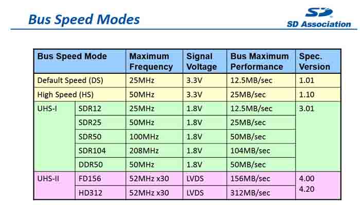
- sd.JPG (54.87 KiB) Viewed 273 times
Sdio cannot run with 42mhz due to a hw issue, chech the errata sheet. At least in 4bit mode, i dont know in 1 bit mode.
[stevestrong – Thu Sep 13, 2018 6:39 am] –
SPI_1 runs with 42mhz and is usable.Sdio cannot run with 42mhz due to a hw issue, chech the errata sheet. At least in 4bit mode, i dont know in 1 bit mode.
Thanks Stevestrong.
I did just google the doc and have a bit of a read but didn’t really understand what it was saying so I don’t understand the problem.
The doc seems to contradict the reference manual too which quotes this
SDIO_CK is the clock to the card: one bit is transferred on both command and data lines
with each clock cycle.
The SDIO uses two clock signals:
• SDIO adapter clock SDIOCLK up to 50 MHz (48 MHz when in use with USB)
• APB2 bus clock (PCLK2)
PCLK2 and SDIO_CK clock frequencies must respect the following condition:
Frequenc(PCLK2) ≥ 3 ⁄ 8 × Frequency(SDIO_CK)
Where is the contradiction?
[flyboy74 – Thu Sep 13, 2018 8:32 am] –
I did just google the doc and have a bit of a read but didn’t really understand what it was saying so I don’t understand the problem.
Well, in this case I would not dig deeper. ![]()
[stevestrong – Thu Sep 13, 2018 8:36 am] –
Which doc?
Where is the contradiction?[flyboy74 – Thu Sep 13, 2018 8:32 am] –
I did just google the doc and have a bit of a read but didn’t really understand what it was saying so I don’t understand the problem.Well, in this case I would not dig deeper.

Then I will never understand. I like learning new things.
Is this the problem you refer too??
SDIO clock divider BYPASS
mode may not work properly
If I am understanding this properly this means that you can’t bypass the divider so that means if you don’t bypass(i.e BYPASS bit is equal to “0”) and use the min value for the divider then max speed of SDIO will be 42MHz
Is this the HW problem you talk about???
Bit 10 BYPASS = 0
Bits 7:0 CLKDIV = 0
where SDIO_CK frequency = SDIOCLK / [CLKDIV + 2].
This gives 82MHz / [0 +2] = 42MHz
With clocks setup like this??
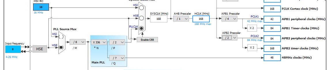
- clocks.JPG (49.74 KiB) Viewed 250 times
2.11.6 No underrun detection with wrong data transmission
Description
In case there is an ongoing data transfer from the SDIO host to the SD card and the hardware flow control is disabled (bit 14 of the SDIO_CLKCR is not set), if an underrun condition occurs, the controller may transmit a corrupted data block (with wrong data word) without detecting the underrun condition when the clock frequencies have the following relationship:
[3 x period(PCLK2) + 3 x period(SDIOCLK)] >= (32 / (BusWidth)) x period(SDIO_CK)
Workaround
Avoid the above-mentioned clock frequency relationship, by:
• Incrementing the APB frequency
• or decreasing the transfer bandwidth
• or reducing SDIO_CK frequency
As workaround, there is only the last option feasible, if we want to keep USB (48Mhz), and no overclocking. The next available frequency lower than 48MHz is the half of it, 24MHz.
I do see 2 options
1. SDIO 1_line running at 42Mhz
2. SDIO 4_line running at 24MHz
If both of these options work then SDIOI 1_line will be same speed at SPI and SDIO 4_line will be double the speed of SPI
If there is an SD slot on board connected to SDIO lines, use that in SDIO_4 mode.
Otherwise use SPI 1 (@42MHz) for max performance.
![[Pending Enhancement] RTC values resetting](https://sparklogic.ru/wp-content/uploads/2019/11/nucleo-l476rg-zestaw-startowy-z-mikrokontrolerem-z-rodziny-stm32-stm32l476-90x90.jpg)