DLO-138 is alternate firmware for DSO-138 and adds second analog channel, two logic channels, more sample depth and serial port data output.
Code: https://github.com/ardyesp/DLO-138
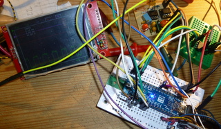
- pic3.png (153.54 KiB) Viewed 8814 times
I see stm32duino.com gets a mention on the github main page, and Stevestrong’s fast TFT lib also gets a mention here…
https://github.com/ardyesp/DLO-138/tree … src/TFTLib
F407, for example. There are chinese boards with that (I have one). Yes, those are not almost-free as BluePills, but, I understand that hardware is much much more capable and non-restricting
If the display update rate is “acceptable” for the user, I see not reason why to go for F407 (although I am aware of all advantages that it would bring).
Btw, @willfly1, congrats, simple and therefore cool look! I like very much the design!
Also have a loooot more RAM = bigger sample buffer.
And It enables the use of an external faster ADC, maybe on the 50MSPS range…
I’m assembling some PCB adapter boards with a F429 and F746 to do some experiments…
It would be great to replace the manual gain switches (and gain pins) with menus and MCP6S92’s ![]()
Might have a go on this ![]()
P.S. BTW is there a video with this setup/code? ![]() how many FPS?
how many FPS?
Otherwise the TFT update, I can tell you, is very fast with the current lib (8 bit parallel, not SPI). Check it out here.
As I told, if there is no speciality requested (like FFT or higher sps), I am convinced that F103 is still a good choice.
But this does not mean that I will not test it with my F407 board ![]()
P.S.: every DSO’s dream is to became like analog one
Otherwise the TFT update, I can tell you, is very fast with the current lib (8 bit parallel, not SPI). Check it out here.
As I told, if there is no speciality requested (like FFT or higher sps), I am convinced that F103 is still a good choice.
But this does not mean that I will not test it with my F407 board ![]()
P.S. BTW is there a video with this setup/code?
P.S. BTW is there a video with this setup/code?
Here:
http://www.jyetech.com/Products/LcdScope/e150.php (I love that “band-witch” part in first line…
http://www.jyetech.com/Products/LcdScop … _Shell.pdf
Here:
http://www.jyetech.com/Products/LcdScope/e150.php (I love that “band-witch” part in first line…
http://www.jyetech.com/Products/LcdScop … _Shell.pdf
at Youtube:
I have tested your program a little bit with the SPI display:
good design, nearly all functions you need and also quick on the SPI display! Super !
Only the rotary encoder is – I think – better integrated in the 10$ O-Scope:
You can select there the “Function” ( timeBase, Offset,…) with the encoder, then switch with button of the encoder to “Parameters” and change the parameters with the same encoder (z.B 20,50,100µs for e.g. timeBase).
It’s quicker with the encoder and you can go to the other functions on the left or right site by turning cw or ccw, you can go in Your SW with the button only ccw.
For instance, if you have select “AUTO”, you have to switch about 10 time to come to the timebase-field.
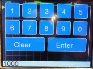
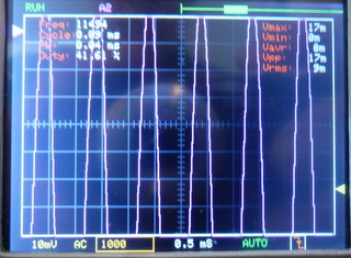
the first picture shows the Touch Panel for set frequency, the second the selected frequency from AD9851:
- DLO138-Set-Frequency-AD9851.JPG (39.58 KiB) Viewed 1381 times
the first picture shows the Touch Panel for set frequency, the second the selected frequency from AD9851:
DLO138-Set-Frequency-AD9851.JPG
DLO138-Show-Frequency_AD9851.JPG
I have aligned the Pin-Mapping for maple mini for my 10$ O-Scope and the DLO-138.
So I can test both variants.
The input area on the display for the frequency is only provisionally for the test.
But on DLO-138 I still haven’t checked that, is it the same block as on DSO-138?
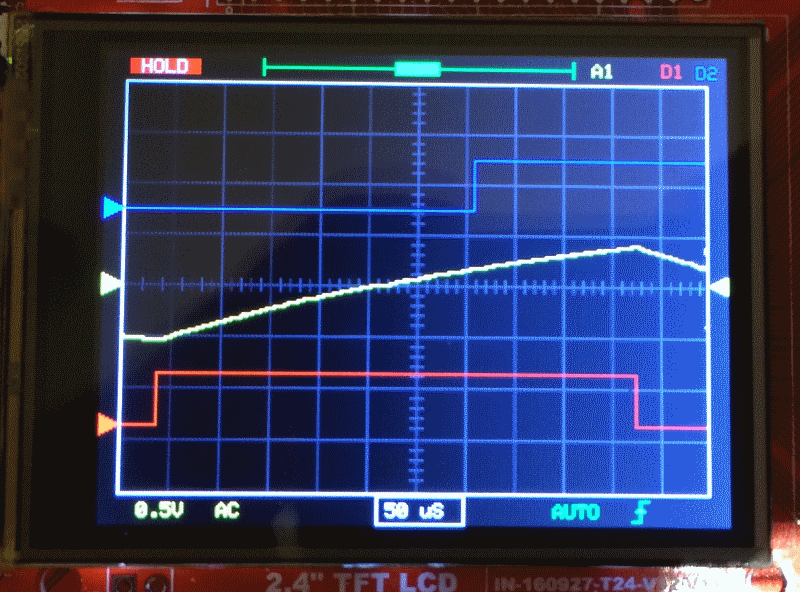
Would be very informative to post some screenshots of square wave at different frequencies of new version(s).
The limitation as I recall is on the analog frontend. I don’t thing the input approach is the best for this…
is that ok (in dlo-138 : display) line 174:
// ————————
void clearNDrawSignals() {
// ————————
static boolean wavesOld[4] = {false,}; <<< ???????
static int16_t yCursorsOld[4];
- DLO-138-02.7z
- (14.75 KiB) Downloaded 200 times
is that ok (in dlo-138 : display) line 174:
// ————————
void clearNDrawSignals() {
// ————————
static boolean wavesOld[4] = {false,}; <<< ???????
static int16_t yCursorsOld[4];
is that ok (in dlo-138 : display) line 174:
// ————————
void clearNDrawSignals() {
// ————————
static boolean wavesOld[4] = {false,}; <<< ???????
static int16_t yCursorsOld[4];
But on DLO-138 I still haven’t checked that, is it the same block as on DSO-138?
On another question about bandwidth, IMO these low sampling ADC’s are good for viewing audio level signals, which is what most hobbyist’s need. Anything above hundred Khz is probably in digital – logic analyzer domain.
Now You can change betweeen functions/labels and the steps/parameters with the rotary encoder. The button of the encoder is only for changing between functions and steps.
But I haveto reduce the storage from 2048 to 1024 steps (because of AD9581/Touch?), I think the trigger is not perfect, perhaps I have to change the levels.
And by long timeBases ( >= 10mS) is a problem with the encoder / switches. On “10$ O-scope” I can do the parameter-changes inside the interrupt-routine inclusive update the small areas on the display.
on Youtube:
Only with the cursors on the left and right side I have problems.
I Changed the on the top of the display the wave-field (A1,A2,D1,D2) more to the right and moved the window-field for the storage of the waves to the left.
Also I split the wave field in four separate fields. Now I can activate / deactivate each channel separate. And I changed the colour of the trigger-edge to orange for falling ( It was difficult to differentiate between them at least for my eyes …)
Now I need the button of the encoder only to start/activate the touch-function.
- DLO138-SPI_Change_Labels_Touch.JPG (56.58 KiB) Viewed 897 times
on the left are the hidden touch-sensorfields for cursor 1…4 for the input signals,
x < 70
y > 60 and y <100: L_vPos1
y > 100 and < 130: L_vPos2
y> 130 and < 160: L_vPos3
y> 160 and < 190: L_vPos4
on the right is the field for the triggerlevel.
X> 280 and < 319
Y>100 and < 200: L_triggerLevel
and the source:
- DLO-138-04.7z
- (15.49 KiB) Downloaded 132 times
As for the trigger: Do you have the external circuit assembled? Or did you change the trigger method?
Because the original schematic has an external op-amp that receives a PWM to set the value and compares it with the input signal and sends the output to a pin that is used to start?/set? the trigger.
There are a bit of artifacts indeed… but might get solved ![]()
I might get a chance to try it out this weekend cause it seems that it will be rainy all weekend long…
yes there is VGEN (on PA10 in my SW)for maple-mini, but it’s open.
and TRIGGER_IN ( PA11 maple_mini).
I have to study the HW / schematic !!
PB8 is TL_PWM, generates the voltage level for the comparator.
PA8 it TRIGGER, receives the logic signal from the comparator.
The chip is labeled U2D. And the other input of the comparator is ADCIN PA0.
Hope it makes it easier for you ![]()
DSO MAPLE
AN_CH1 PA0 PB0
AN_CH2 PA4 PA0 ( problem with spi1 CS=PA4 ???)
TRIGGER_IN PA8 PA11
TRIGGER_LEVEL PA8 PB8
VSENSSEL1 PA2 PA2
VSENSSEL2 PA1 PA1
CPLSEL PA3 PA3
VGEN PB9 PA10
TL_PWM PB8 ????
VGEN I can’t see in the schematic
I haven’t found TL_PWM in the original-software DLO-138 (global.h)
DSO MAPLE
AN_CH1 PA0 PB0
AN_CH2 PA4 PA0 ( problem with spi1 CS=PA4 ???)
TRIGGER_IN PA8 PA11
TRIGGER_LEVEL PA8 PB8
VSENSSEL1 PA2 PA2
VSENSSEL2 PA1 PA1
CPLSEL PA3 PA3
VGEN PB9 PA10
TL_PWM PB8 ????
VGEN I can’t see in the schematic
I haven’t found TL_PWM in the original-software DLO-138 (global.h)
https://youtu.be/M8DlqzZ3ROI
Good work, thx.
Could you share the MINIMUM code for continuous Serial Output only, without displays, encoders, switchers, EEPROM and so on.
Only RAW array – Time, ADC1, ADC2 for PC-based analyzing.
It`s hard for me cleaning many unused functions and variables from the code.
Regards,
MagSem
So I moved the “window” for the storage to the right and separate the fields for the channels A1, A2, D1 and D2.
If a channel is active, he has his colour, otherwise he is greyed. On the right of the channels I have moved the frequency input from DDS AD9851.
Also the fields on the bottom for timebase, triggerType and triggerEdge are bigger and more separated.
So is the handling more comfortable.
By the way I have changed some colors , e.g. for the storage blue (like a watertank) ![]() , and for analog-Channel 1 to purple (it looks more like an old scope
, and for analog-Channel 1 to purple (it looks more like an old scope ![]() ).
).
- DLO138-SPI_modified_Touch_Labels.JPG (52.52 KiB) Viewed 911 times
But I think that maybe you could move the channel labels to the side instead of the “slider”. Sliding up and down is not that intuitive.
But it’s cleaner look.
I didn’t have the chance to try it out this weekend…
I’ll try to change the pinout meanwhile to try to speed up the testing part…
but I think the sliders must be on the side for moving up and down with the encoder, but activate by touch.
As next I have to make the preamp’s for testing the offset-config.
My last code for touch is here:
- DLO-138-05.7z
- (16.47 KiB) Downloaded 101 times
- DLO-138-05.7z
- (16.47 KiB) Downloaded 114 times
But perhaps also with the MCP6S91/ 92. I have to test it separate with the SPI, if I can change the clock-divider temporarily for the OP (max 10Mhz) and the SPI-display(max 20 MHz?).
How many pins do you have free? MCP6S only needs CLK,MOSI,CS(1 for each MCP…) 4 total for 2 MCP’s.
But you can use “shiftOut” and save SPI troubles
Otherwise, I think you can do this:
_SPI->beginTransaction(SPISettings(9000000, MSBFIRST, SPI_MODE0)); //before MCP access 9Mhz to be safe
…
_SPI->beginTransaction(SPISettings(36000000, MSBFIRST, SPI_MODE0)); //after MCP access 36Mhz for the display. (if _SPI = SPI1)
thanks for your example for changing frequency.
I hope that I need only one pin for each MCP, only for CS(n),
I take the same SCK (PA5), MOSI(PA7) Pins like the SPI-TFT (spi1).
There is a nice project:
http://www.rotwang.co.uk/projects/energy_monitor.html
with two spi-devices (ADC-MCP3002 and PGA MCP6S91) with Arduino-Code.
But I think at first I try this:
Perhaps was the voltage-divider on the input (51k / 1k) not low resistance enough or the Voltage Vcc not stable or …?
But with Vin (of the Maple Mini on USB) its nearly exact.
Therefore I modified it to MCP6S92.h / cpp
I made on the left corner of the display for testing a small touch-area for activating the PGA MCP6S91.
A video from the first test is here ( only for switching between 16 and 32, because I have problems with the offset):
the modified lib is here:
- MCP6S92.h
- (608 Bytes) Downloaded 190 times
Therefore I modified it to MCP6S92.h / cpp
I made on the left corner of the display for testing a small touch-area for activating the PGA MCP6S91.
A video from the first test is here ( only for switching between 16 and 32, because I have problems with the offset):
the modified lib is here:
MCP6S92.h
MCP6S92.cpp
I have now no problems with the MCP6S91, the gain switching with SPI is ok. I have only to make something with the trigger and offset (like DSO138).
But I said in the Blog touch is more intuitive for changing labels, but to activate TOUCH with a real button is a little bit antique.
Therefore I tried it with SPI , but no success.
Back to URTOUCH I activated the touch with an ISR on TOUCH_IRQ-Pin and don’t need the loop:
while (touch.available() …
Now I can use the touch-function without pressing the button (the button on the encoder is now free ) ![]()
![]()
That’s quick and real intuitive ! ![]()
I think with the DSO150 you can make only a 1 channel o-scope, because you need 4 pins for gain selection.
I think it’s better with the MCP6S91/92 (1 Pin) or a combination from DSO150 ( only inputstage with HC4053 (1Pin))
and MCP6S91/92.
The input of the DSO150 is a little bit better and easier to realize as the of the DSO138 and you can build in an overvoltage-protection with 2 diodes or two antiparallel white/blue leds (not tested, but very small leakage currents, but perhaps problems with capacity).
it’s not ever easy to hit the small touch-fields with thick finger’s ! ![]()
Yep, the small areas are a bit difficult do get using fingers…that is why I started to use the encoder. But it’s not perfect too…
Maybe a 15″ touchscreen could help us ![]()
Touch IRQ is a great feature as it doesn’t affect the refresh rate ![]()
The HC input stage approach can lead to a better bandwidth by using better op-amps. But that could be used for the F303 option ![]()
I have mounted a parallel resistance from about 1.8 kOhm between 3.3V and PA12, so I can program the Pill via USB with Arduino IDE 1.8.4. The memory is set to 128k (in the STMFlashloader). I have also shorted the 100 kOhm resitance on Boot1, so I can use PB2 (perhaps for a 8-bit display).
I take the encoders from madias (multi-encoder with timer1).
I use this pins:
A0 Analog Input 1
B0 Analog Input 2
B10 TFT_DC
A7 TFT_MOSI
(A6 TFT_MISO)
A5 TFT_SCK
A4 TFT_CS
3.3V TFT_RST
B3 Encoder_0
B4 Encoder_0
B12 Encoder_1
B13 Encoder_1
B6 TEST_WAVE
The program runs stable, the encoders (EC11, KY-040) have no problems with bouncing.
Now I have to build the input amplifiers (with MC6S22 ?)
Good information (inl. schematic) for preamps is on this page :
damusician.com/dpscope/overview.html
mausi_mick
I haven’t debugged it yet… I don’t have an oscilloscope to check that out so it might be working ok but that’s what I saw on the screen.
I have also looked to the input stage of the nano DSO203. Seems good and might be upgraded with better opamps to get more BW:
https://goo.gl/images/58mzQy
P.S. Does anyone have a version of the DSO150 code? That one might be interesting also… I’m tempted to buy one of these…
P.S.2 Can you share the code?
I think the difficulties come with the TFT-Lib. Therefore I tried it with an I2C DAC (MCP4725) with success, but In need
Pins PB6 PB7, so I had to eliminate the TEST_WAVE on PB&
I think I take the MCP6S22 for amplifying (similar DP-Scope V1.3)
I modified the menu for service with the second encoder, on bottom left I start with the timeBase, than Vgain1, Vgain2 (from MCPS622), Offset1, Offset2 (from 2 MCP4725, in work, not finished), trigType and trigEdge …
The handling with the encoders from madias is normaly quick exapt for sampling (with timeBase >2ms).
I think , the preamp in DSO203 is very complex , is much work.
Perhaps It’s easier to take a LTC6912-1 (2 channel ,gain: 0,1,2,5,10,20,100) or an LTC6912-2 with gain 01,2,4,8,16,32,64),
and you need only a input stage(for dividing and protection with clamp-diodes) and a voltage spltter to 2×3.3V or 2x5V.
The LTC has also 3 wire SPI.
[mausi_mick – Sun Sep 03, 2017 11:08 am] –
Rexanet,I think , the preamp in DSO203 is very complex , is much work.
Perhaps It’s easier to take a LTC6912-1 (2 channel ,gain: 0,1,2,5,10,20,100) or an LTC6912-2 with gain 01,2,4,8,16,32,64),
and you need only a input stage(for dividing and protection with clamp-diodes) and a voltage spltter to 2×3.3V or 2x5V.
The LTC has also 3 wire SPI.
Yes, I know it’s a bit more complex but if more bandwidth is needed it’s the way to go ![]()
That LTC6912 seems a good choice, the main problem is the price/availability. The MCP6S92 I can ask for some samples to make some experiments, the LTC I don’t know if they send samples… and it’s $4+ on digikey…
Do you have a video with the 2 knobs setup?
now I have big problems – I think with the Adafruit_ILI9341_STM – lib. The SPI graphic functioned, but I can’t activate other SPI
devices like MCP6S91/92 or MCP4822 (DAC). I reduced the speed to 9MHz and back to 36MHz, but with no success.
I tested it with “blue-Pill” and Maple-Mini – the same. –
I tested MCP6S91/92 on UNO with success.
(I think I prefer the S91 , because it’s’ a XOR function,they have only one output .
On the Ref-Input of the S91 I can change the offset …)
It’s for me more difficult to get the CP1017N opto-switches in the schematic from the DSO203 as the preamp LTC6912,
I can get it for 4.37 € by www.voelkner.de , I think it’s a good price for 2 channels.
But the small layout could be a problem for me.
But I don’t know if I have their the same problems with the SPI, ???
next if that involved playing with the clock, mode & polarity settings or not, anyway move it to spi2
check it still works
restore the display to spi1
stephen
I have the same problem with the MCP4812/22 (SPI-DAC) and changed therefore to a I2C version (MCP4725?).
I tried different frequencies ( 9MHz, 10 MHz, 20MHz and 36MHz) for the MCPs and 36 MHz for the ILI9341.
But i don’t know what I have changed in the programs meanwhile. Perhaps its a problem with the Arduino IDE (going from 1.6.3 to 1.84) or the newest STM32 – lib ?
[mausi_mick – Fri Sep 08, 2017 1:38 am] –
Rexanet,now I have big problems – I think with the Adafruit_ILI9341_STM – lib. The SPI graphic functioned, but I can’t activate other SPI
devices like MCP6S91/92 or MCP4822 (DAC). I reduced the speed to 9MHz and back to 36MHz, but with no success.
I tested it with “blue-Pill” and Maple-Mini – the same. –I tested MCP6S91/92 on UNO with success.
(I think I prefer the S91 , because it’s’ a XOR function,they have only one output .
On the Ref-Input of the S91 I can change the offset …)It’s for me more difficult to get the CP1017N opto-switches in the schematic from the DSO203 as the preamp LTC6912,
I can get it for 4.37 € by www.voelkner.de , I think it’s a good price for 2 channels.
But the small layout could be a problem for me.But I don’t know if I have their the same problems with the SPI, ???
Hi mausi_mick,
CP1017N I´m going to get from aliexpress, 3.21€ for 10 pieces : https://www.aliexpress.com/item/Free-Sh … 38858.html
It’s not fast but it seems to be a good price…
That point on offset with the S91 is a good point.
I was thinking on S92 to allow to have 2 channels @ 1MSPS or 1 channel @ 2MSPS.
I think that your problems might be related to an Adafruit_ILI9341_STM lib update (without any certainty). I have faced some problems on other platforms (ESP32 and ESP8266) when upgrading this lib…
I have one Arduino IDE for each platform to avoid upgrading problems…
It might be related to CS activation and de-activation.
If you send me the code I can have a look.
Maybe try this library:
https://github.com/Bodmer/TFT_ILI9341
I recently experimented with some CPU load indication projects, it was used there. Existing Adafruit library should probably be deleted/moved then.
- DLO-138-MaMi_01.7z
- (21.54 KiB) Downloaded 139 times
ich habe beim compilieren des sketch immer die fehler meldung: “Warning: register range not in ascending order”
I have always compiled the sketch the error: “Warning: register range not in ascending order”
W10, Arduino 1.8.4
Which core are u using? [german]:
Bitte die komplette Fehlermeldung hier posten, einschliesslich Dateiname, Zeilennummer, usw.
Welcher Core wird verwendet?
C:\Users\Meiner\AppData\Local\Temp\ccBTRPkR.s: Assembler messages:
C:\Users\Meiner\AppData\Local\Temp\ccBTRPkR.s:495: Warning: register range not in ascending order
C:\Users\Meiner\AppData\Local\Temp\ccBTRPkR.s:495: Warning: register range not in ascending order
C:\Users\Meiner\AppData\Local\Temp\ccBTRPkR.s:495: Warning: register range not in ascending order
C:\Users\Meiner\AppData\Local\Temp\ccBTRPkR.s:495: Warning: register range not in ascending order
C:\Users\Meiner\AppData\Local\Temp\ccBTRPkR.s:497: Warning: register range not in ascending order
C:\Users\Meiner\AppData\Local\Temp\ccBTRPkR.s:497: Warning: register range not in ascending order
C:\Users\Meiner\AppData\Local\Temp\ccBTRPkR.s:497: Warning: register range not in ascending order
C:\Users\Meiner\AppData\Local\Temp\ccBTRPkR.s:497: Warning: register range not in ascending order
C:\Users\Meiner\AppData\Local\Temp\ccBTRPkR.s:546: Warning: register range not in ascending order
C:\Users\Meiner\AppData\Local\Temp\ccBTRPkR.s:546: Warning: register range not in ascending order
C:\Users\Meiner\AppData\Local\Temp\ccBTRPkR.s:546: Warning: register range not in ascending order
C:\Users\Meiner\AppData\Local\Temp\ccBTRPkR.s:548: Warning: register range not in ascending order
C:\Users\Meiner\AppData\Local\Temp\ccBTRPkR.s:548: Warning: register range not in ascending order
C:\Users\Meiner\AppData\Local\Temp\ccBTRPkR.s:548: Warning: register range not in ascending order
C:\Users\Meiner\AppData\Local\Temp\ccBTRPkR.s:595: Warning: register range not in ascending order
C:\Users\Meiner\AppData\Local\Temp\ccBTRPkR.s:595: Warning: register range not in ascending order
C:\Users\Meiner\AppData\Local\Temp\ccBTRPkR.s:595: Warning: register range not in ascending order
C:\Users\Meiner\AppData\Local\Temp\ccBTRPkR.s:595: Warning: register range not in ascending order
C:\Users\Meiner\AppData\Local\Temp\ccBTRPkR.s:595: Warning: register range not in ascending order
C:\Users\Meiner\AppData\Local\Temp\ccBTRPkR.s:597: Warning: register range not in ascending order
C:\Users\Meiner\AppData\Local\Temp\ccBTRPkR.s:597: Warning: register range not in ascending order
C:\Users\Meiner\AppData\Local\Temp\ccBTRPkR.s:597: Warning: register range not in ascending order
C:\Users\Meiner\AppData\Local\Temp\ccBTRPkR.s:597: Warning: register range not in ascending order
C:\Users\Meiner\AppData\Local\Temp\ccBTRPkR.s:597: Warning: register range not in ascending order
Archiving built core (caching) in:
C:\Users\Meiner\AppData\Local\Temp\arduino_cache_157334\core\core_Arduin
o_STM32-master_STM32F1_genericSTM32F103C_device_variant_STM32F103C8,uplo
ad_method_serialMethod,cpu_speed_speed_72mhz,opt_osstd_788985e64bb343182
e2e5afb824970d0.a
Der Sketch verwendet 37900 Bytes (57%) des Programmspeicherplatzes. Das Maximum sind 65536 Bytes.
Globale Variablen verwenden 17408 Bytes (85%) des dynamischen Speichers, 3072 Bytes für lokale Variablen verbleiben.
Das Maximum sind 20480 Bytes.
Wenig Arbeitsspeicher verfügbar, es können Stabilitätsprobleme auftreten.
File->Preferences->Show verbose output during:. Tick boxes for compilation and upload
and post here the complete message window content.
the administered binaries run.
the latest stock firmware is also running.
C:\Arduino1.8.3\arduino-builder -dump-prefs -logger=machine -hardware C:\Arduino1.8.3\hardware -hardware C:\Users\Meiner\AppData\Local\Arduino15\packages -tools C:\Arduino1.8.3\tools-builder -tools C:\Arduino1.8.3\hardware\tools\avr -tools C:\Users\Meiner\AppData\Local\Arduino15\packages -built-in-libraries C:\Arduino1.8.3\libraries -libraries C:\Users\Meiner\Documents\Arduino\libraries -fqbn=Arduino_STM32-master:STM32F1:genericSTM32F103C:device_variant=STM32F103C8,upload_method=serialMethod,cpu_speed=speed_72mhz,opt=osstd -ide-version=10804 -build-path C:\Users\Meiner\AppData\Local\Temp\arduino_build_317073 -warnings=none -build-cache C:\Users\Meiner\AppData\Local\Temp\arduino_cache_166353 -prefs=build.warn_data_percentage=75 -verbose C:\3D_Drucker\DSO138\DLO-138_neu\DLO-138\DLO-138.ino

C:\Arduino1.8.3\arduino-builder -compile -logger=machine -hardware C:\Arduino1.8.3\hardware -hardware C:\Users\Meiner\AppData\Local\Arduino15\packages -tools C:\Arduino1.8.3\tools-builder -tools C:\Arduino1.8.3\hardware\tools\avr -tools C:\Users\Meiner\AppData\Local\Arduino15\packages -built-in-libraries C:\Arduino1.8.3\libraries -libraries C:\Users\Meiner\Documents\Arduino\libraries -fqbn=Arduino_STM32-master:STM32F1:genericSTM32F103C:device_variant=STM32F103C8,upload_method=serialMethod,cpu_speed=speed_72mhz,opt=osstd -ide-version=10804 -build-path C:\Users\Meiner\AppData\Local\Temp\arduino_build_317073 -warnings=none -build-cache C:\Users\Meiner\AppData\Local\Temp\arduino_cache_166353 -prefs=build.warn_data_percentage=75 -verbose C:\3D_Drucker\DSO138\DLO-138_neu\DLO-138\DLO-138.ino

Using board 'genericSTM32F103C' from platform in folder: C:\Arduino1.8.3\hardware\Arduino_STM32-master\STM32F1

Using core 'maple' from platform in folder: C:\Arduino1.8.3\hardware\Arduino_STM32-master\STM32F1

Detecting libraries used...

"C:\Users\Meiner\AppData\Local\Arduino15\packages\arduino\tools\arm-none-eabi-gcc\5 2016q3/bin/arm-none-eabi-g++" -c -g -Os -w -DDEBUG_LEVEL=DEBUG_NONE -std=gnu++11  -ffunction-sections -fdata-sections -nostdlib --param max-inline-insns-single=500 -fno-rtti -fno-exceptions -DBOARD_generic_stm32f103c -DVECT_TAB_ADDR=0x8000000 -DERROR_LED_PORT=GPIOB -DERROR_LED_PIN=1 -w -x c++ -E -CC -mcpu=cortex-m3 -DF_CPU=72000000L -DARDUINO=10804 -DARDUINO_GENERIC_STM32F103C -DARDUINO_ARCH_STM32F1  -DCONFIG_MAPLE_MINI_NO_DISABLE_DEBUG -DMCU_STM32F103C8  -mthumb  -march=armv7-m -D__STM32F1__ -DMCU_STM32F103C8  -mthumb  -march=armv7-m -D__STM32F1__ "-IC:\Arduino1.8.3\hardware\Arduino_STM32-master\STM32F1\system/libmaple" "-IC:\Arduino1.8.3\hardware\Arduino_STM32-master\STM32F1\system/libmaple/include" "-IC:\Arduino1.8.3\hardware\Arduino_STM32-master\STM32F1\system/libmaple/stm32f1/include"                                                           "-IC:\Arduino1.8.3\hardware\Arduino_STM32-master\STM32F1\system/libmaple/usb/stm32f1" "-IC:\Arduino1.8.3\hardware\Arduino_STM32-master\STM32F1\system/libmaple/usb/usb_lib" "-IC:\Arduino1.8.3\hardware\Arduino_STM32-master\STM32F1\cores\maple" "-IC:\Arduino1.8.3\hardware\Arduino_STM32-master\STM32F1\variants\generic_stm32f103c" "C:\Users\Meiner\AppData\Local\Temp\arduino_build_317073\sketch\DLO-138.ino.cpp" -o "nul"

"C:\Users\Meiner\AppData\Local\Arduino15\packages\arduino\tools\arm-none-eabi-gcc\5 2016q3/bin/arm-none-eabi-g++" -c -g -Os -w -DDEBUG_LEVEL=DEBUG_NONE -std=gnu++11  -ffunction-sections -fdata-sections -nostdlib --param max-inline-insns-single=500 -fno-rtti -fno-exceptions -DBOARD_generic_stm32f103c -DVECT_TAB_ADDR=0x8000000 -DERROR_LED_PORT=GPIOB -DERROR_LED_PIN=1 -w -x c++ -E -CC -mcpu=cortex-m3 -DF_CPU=72000000L -DARDUINO=10804 -DARDUINO_GENERIC_STM32F103C -DARDUINO_ARCH_STM32F1  -DCONFIG_MAPLE_MINI_NO_DISABLE_DEBUG -DMCU_STM32F103C8  -mthumb  -march=armv7-m -D__STM32F1__ -DMCU_STM32F103C8  -mthumb  -march=armv7-m -D__STM32F1__ "-IC:\Arduino1.8.3\hardware\Arduino_STM32-master\STM32F1\system/libmaple" "-IC:\Arduino1.8.3\hardware\Arduino_STM32-master\STM32F1\system/libmaple/include" "-IC:\Arduino1.8.3\hardware\Arduino_STM32-master\STM32F1\system/libmaple/stm32f1/include"                                                           "-IC:\Arduino1.8.3\hardware\Arduino_STM32-master\STM32F1\system/libmaple/usb/stm32f1" "-IC:\Arduino1.8.3\hardware\Arduino_STM32-master\STM32F1\system/libmaple/usb/usb_lib" "-IC:\Arduino1.8.3\hardware\Arduino_STM32-master\STM32F1\cores\maple" "-IC:\Arduino1.8.3\hardware\Arduino_STM32-master\STM32F1\variants\generic_stm32f103c" "-IC:\Arduino1.8.3\hardware\Arduino_STM32-master\STM32F1\libraries\EEPROM" "C:\Users\Meiner\AppData\Local\Temp\arduino_build_317073\sketch\DLO-138.ino.cpp" -o "nul"

"C:\Users\Meiner\AppData\Local\Arduino15\packages\arduino\tools\arm-none-eabi-gcc\5 2016q3/bin/arm-none-eabi-g++" -c -g -Os -w -DDEBUG_LEVEL=DEBUG_NONE -std=gnu++11  -ffunction-sections -fdata-sections -nostdlib --param max-inline-insns-single=500 -fno-rtti -fno-exceptions -DBOARD_generic_stm32f103c -DVECT_TAB_ADDR=0x8000000 -DERROR_LED_PORT=GPIOB -DERROR_LED_PIN=1 -w -x c++ -E -CC -mcpu=cortex-m3 -DF_CPU=72000000L -DARDUINO=10804 -DARDUINO_GENERIC_STM32F103C -DARDUINO_ARCH_STM32F1  -DCONFIG_MAPLE_MINI_NO_DISABLE_DEBUG -DMCU_STM32F103C8  -mthumb  -march=armv7-m -D__STM32F1__ -DMCU_STM32F103C8  -mthumb  -march=armv7-m -D__STM32F1__ "-IC:\Arduino1.8.3\hardware\Arduino_STM32-master\STM32F1\system/libmaple" "-IC:\Arduino1.8.3\hardware\Arduino_STM32-master\STM32F1\system/libmaple/include" "-IC:\Arduino1.8.3\hardware\Arduino_STM32-master\STM32F1\system/libmaple/stm32f1/include"                                                           "-IC:\Arduino1.8.3\hardware\Arduino_STM32-master\STM32F1\system/libmaple/usb/stm32f1" "-IC:\Arduino1.8.3\hardware\Arduino_STM32-master\STM32F1\system/libmaple/usb/usb_lib" "-IC:\Arduino1.8.3\hardware\Arduino_STM32-master\STM32F1\cores\maple" "-IC:\Arduino1.8.3\hardware\Arduino_STM32-master\STM32F1\variants\generic_stm32f103c" "-IC:\Arduino1.8.3\hardware\Arduino_STM32-master\STM32F1\libraries\EEPROM" "-IC:\Users\Meiner\Documents\Arduino\libraries\Adafruit-GFX-Library-master" "C:\Users\Meiner\AppData\Local\Temp\arduino_build_317073\sketch\DLO-138.ino.cpp" -o "nul"

Using cached library dependencies for file: C:\Users\Meiner\AppData\Local\Temp\arduino_build_317073\sketch\src\TFTLib\Adafruit_TFTLCD_8bit_STM32.cpp

Using cached library dependencies for file: C:\Users\Meiner\AppData\Local\Temp\arduino_build_317073\sketch\src\TFTLib\hx8347g.cpp

Using cached library dependencies for file: C:\Users\Meiner\AppData\Local\Temp\arduino_build_317073\sketch\src\TFTLib\hx8357x.cpp

Using cached library dependencies for file: C:\Users\Meiner\AppData\Local\Temp\arduino_build_317073\sketch\src\TFTLib\ili932x.cpp

Using cached library dependencies for file: C:\Users\Meiner\AppData\Local\Temp\arduino_build_317073\sketch\src\TFTLib\ili9341.cpp

Using cached library dependencies for file: C:\Arduino1.8.3\hardware\Arduino_STM32-master\STM32F1\libraries\EEPROM\EEPROM.cpp

Using cached library dependencies for file: C:\Arduino1.8.3\hardware\Arduino_STM32-master\STM32F1\libraries\EEPROM\flash_stm32.c

Using cached library dependencies for file: C:\Users\Meiner\Documents\Arduino\libraries\Adafruit-GFX-Library-master\Adafruit_GFX.cpp

Using cached library dependencies for file: C:\Users\Meiner\Documents\Arduino\libraries\Adafruit-GFX-Library-master\glcdfont.c

Generating function prototypes...

"C:\Users\Meiner\AppData\Local\Arduino15\packages\arduino\tools\arm-none-eabi-gcc\5 2016q3/bin/arm-none-eabi-g++" -c -g -Os -w -DDEBUG_LEVEL=DEBUG_NONE -std=gnu++11  -ffunction-sections -fdata-sections -nostdlib --param max-inline-insns-single=500 -fno-rtti -fno-exceptions -DBOARD_generic_stm32f103c -DVECT_TAB_ADDR=0x8000000 -DERROR_LED_PORT=GPIOB -DERROR_LED_PIN=1 -w -x c++ -E -CC -mcpu=cortex-m3 -DF_CPU=72000000L -DARDUINO=10804 -DARDUINO_GENERIC_STM32F103C -DARDUINO_ARCH_STM32F1  -DCONFIG_MAPLE_MINI_NO_DISABLE_DEBUG -DMCU_STM32F103C8  -mthumb  -march=armv7-m -D__STM32F1__ -DMCU_STM32F103C8  -mthumb  -march=armv7-m -D__STM32F1__ "-IC:\Arduino1.8.3\hardware\Arduino_STM32-master\STM32F1\system/libmaple" "-IC:\Arduino1.8.3\hardware\Arduino_STM32-master\STM32F1\system/libmaple/include" "-IC:\Arduino1.8.3\hardware\Arduino_STM32-master\STM32F1\system/libmaple/stm32f1/include"                                                           "-IC:\Arduino1.8.3\hardware\Arduino_STM32-master\STM32F1\system/libmaple/usb/stm32f1" "-IC:\Arduino1.8.3\hardware\Arduino_STM32-master\STM32F1\system/libmaple/usb/usb_lib" "-IC:\Arduino1.8.3\hardware\Arduino_STM32-master\STM32F1\cores\maple" "-IC:\Arduino1.8.3\hardware\Arduino_STM32-master\STM32F1\variants\generic_stm32f103c" "-IC:\Arduino1.8.3\hardware\Arduino_STM32-master\STM32F1\libraries\EEPROM" "-IC:\Users\Meiner\Documents\Arduino\libraries\Adafruit-GFX-Library-master" "C:\Users\Meiner\AppData\Local\Temp\arduino_build_317073\sketch\DLO-138.ino.cpp" -o "C:\Users\Meiner\AppData\Local\Temp\arduino_build_317073\preproc\ctags_target_for_gcc_minus_e.cpp"

"C:\Arduino1.8.3\tools-builder\ctags\5.8-arduino11/ctags" -u --language-force=c++ -f - --c++-kinds=svpf --fields=KSTtzns --line-directives "C:\Users\Meiner\AppData\Local\Temp\arduino_build_317073\preproc\ctags_target_for_gcc_minus_e.cpp"

Sketch wird kompiliert...

"C:\Users\Meiner\AppData\Local\Arduino15\packages\arduino\tools\arm-none-eabi-gcc\5 2016q3/bin/arm-none-eabi-g++" -c -g -Os -w -DDEBUG_LEVEL=DEBUG_NONE -std=gnu++11 -MMD -ffunction-sections -fdata-sections -nostdlib --param max-inline-insns-single=500 -fno-rtti -fno-exceptions -DBOARD_generic_stm32f103c -DVECT_TAB_ADDR=0x8000000 -DERROR_LED_PORT=GPIOB -DERROR_LED_PIN=1 -mcpu=cortex-m3 -DF_CPU=72000000L -DARDUINO=10804 -DARDUINO_GENERIC_STM32F103C -DARDUINO_ARCH_STM32F1  -DCONFIG_MAPLE_MINI_NO_DISABLE_DEBUG -DMCU_STM32F103C8  -mthumb  -march=armv7-m -D__STM32F1__ -DMCU_STM32F103C8  -mthumb  -march=armv7-m -D__STM32F1__ "-IC:\Arduino1.8.3\hardware\Arduino_STM32-master\STM32F1\system/libmaple" "-IC:\Arduino1.8.3\hardware\Arduino_STM32-master\STM32F1\system/libmaple/include" "-IC:\Arduino1.8.3\hardware\Arduino_STM32-master\STM32F1\system/libmaple/stm32f1/include"                                                           "-IC:\Arduino1.8.3\hardware\Arduino_STM32-master\STM32F1\system/libmaple/usb/stm32f1" "-IC:\Arduino1.8.3\hardware\Arduino_STM32-master\STM32F1\system/libmaple/usb/usb_lib" "-IC:\Arduino1.8.3\hardware\Arduino_STM32-master\STM32F1\cores\maple" "-IC:\Arduino1.8.3\hardware\Arduino_STM32-master\STM32F1\variants\generic_stm32f103c" "-IC:\Arduino1.8.3\hardware\Arduino_STM32-master\STM32F1\libraries\EEPROM" "-IC:\Users\Meiner\Documents\Arduino\libraries\Adafruit-GFX-Library-master" "C:\Users\Meiner\AppData\Local\Temp\arduino_build_317073\sketch\DLO-138.ino.cpp" -o "C:\Users\Meiner\AppData\Local\Temp\arduino_build_317073\sketch\DLO-138.ino.cpp.o"

C:\Users\Meiner\AppData\Local\Temp\ccddTvDp.s: Assembler messages:
C:\Users\Meiner\AppData\Local\Temp\ccddTvDp.s:479: Warning: register range not in ascending order
C:\Users\Meiner\AppData\Local\Temp\ccddTvDp.s:479: Warning: register range not in ascending order
C:\Users\Meiner\AppData\Local\Temp\ccddTvDp.s:479: Warning: register range not in ascending order
C:\Users\Meiner\AppData\Local\Temp\ccddTvDp.s:479: Warning: register range not in ascending order
C:\Users\Meiner\AppData\Local\Temp\ccddTvDp.s:481: Warning: register range not in ascending order
C:\Users\Meiner\AppData\Local\Temp\ccddTvDp.s:481: Warning: register range not in ascending order
C:\Users\Meiner\AppData\Local\Temp\ccddTvDp.s:481: Warning: register range not in ascending order
C:\Users\Meiner\AppData\Local\Temp\ccddTvDp.s:481: Warning: register range not in ascending order
C:\Users\Meiner\AppData\Local\Temp\ccddTvDp.s:530: Warning: register range not in ascending order
C:\Users\Meiner\AppData\Local\Temp\ccddTvDp.s:530: Warning: register range not in ascending order
C:\Users\Meiner\AppData\Local\Temp\ccddTvDp.s:530: Warning: register range not in ascending order
C:\Users\Meiner\AppData\Local\Temp\ccddTvDp.s:532: Warning: register range not in ascending order
C:\Users\Meiner\AppData\Local\Temp\ccddTvDp.s:532: Warning: register range not in ascending order
C:\Users\Meiner\AppData\Local\Temp\ccddTvDp.s:532: Warning: register range not in ascending order
C:\Users\Meiner\AppData\Local\Temp\ccddTvDp.s:579: Warning: register range not in ascending order
C:\Users\Meiner\AppData\Local\Temp\ccddTvDp.s:579: Warning: register range not in ascending order
C:\Users\Meiner\AppData\Local\Temp\ccddTvDp.s:579: Warning: register range not in ascending order
C:\Users\Meiner\AppData\Local\Temp\ccddTvDp.s:579: Warning: register range not in ascending order
C:\Users\Meiner\AppData\Local\Temp\ccddTvDp.s:579: Warning: register range not in ascending order
C:\Users\Meiner\AppData\Local\Temp\ccddTvDp.s:581: Warning: register range not in ascending order
C:\Users\Meiner\AppData\Local\Temp\ccddTvDp.s:581: Warning: register range not in ascending order
C:\Users\Meiner\AppData\Local\Temp\ccddTvDp.s:581: Warning: register range not in ascending order
C:\Users\Meiner\AppData\Local\Temp\ccddTvDp.s:581: Warning: register range not in ascending order
C:\Users\Meiner\AppData\Local\Temp\ccddTvDp.s:581: Warning: register range not in ascending order
Zuvor kompilierte Datei wird verwendet: C:\Users\Meiner\AppData\Local\Temp\arduino_build_317073\sketch\src\TFTLib\Adafruit_TFTLCD_8bit_STM32.cpp.o
Zuvor kompilierte Datei wird verwendet: C:\Users\Meiner\AppData\Local\Temp\arduino_build_317073\sketch\src\TFTLib\hx8347g.cpp.o
Zuvor kompilierte Datei wird verwendet: C:\Users\Meiner\AppData\Local\Temp\arduino_build_317073\sketch\src\TFTLib\hx8357x.cpp.o
Zuvor kompilierte Datei wird verwendet: C:\Users\Meiner\AppData\Local\Temp\arduino_build_317073\sketch\src\TFTLib\ili932x.cpp.o
Zuvor kompilierte Datei wird verwendet: C:\Users\Meiner\AppData\Local\Temp\arduino_build_317073\sketch\src\TFTLib\ili9341.cpp.o
Compiling libraries...
Compiling library "EEPROM"
Zuvor kompilierte Datei wird verwendet: C:\Users\Meiner\AppData\Local\Temp\arduino_build_317073\libraries\EEPROM\flash_stm32.c.o
Zuvor kompilierte Datei wird verwendet: C:\Users\Meiner\AppData\Local\Temp\arduino_build_317073\libraries\EEPROM\EEPROM.cpp.o
Compiling library "Adafruit-GFX-Library-master"
Zuvor kompilierte Datei wird verwendet: C:\Users\Meiner\AppData\Local\Temp\arduino_build_317073\libraries\Adafruit-GFX-Library-master\glcdfont.c.o
Zuvor kompilierte Datei wird verwendet: C:\Users\Meiner\AppData\Local\Temp\arduino_build_317073\libraries\Adafruit-GFX-Library-master\Adafruit_GFX.cpp.o
Compiling core...
Zuvor kompilierte Datei wird verwendet: C:\Users\Meiner\AppData\Local\Temp\arduino_build_317073\core\wirish\start.S.o
Zuvor kompilierte Datei wird verwendet: C:\Users\Meiner\AppData\Local\Temp\arduino_build_317073\core\wirish\start_c.c.o
Zuvor kompilierte Datei wird verwendet: C:\Users\Meiner\AppData\Local\Temp\arduino_build_317073\core\wirish\syscalls.c.o
Zuvor kompilierte Datei wird verwendet: C:\Users\Meiner\AppData\Local\Temp\arduino_build_317073\core\board.cpp.o
Zuvor kompilierte Datei wird verwendet: C:\Users\Meiner\AppData\Local\Temp\arduino_build_317073\core\wirish\boards.cpp.o
Zuvor kompilierte Datei wird verwendet: C:\Users\Meiner\AppData\Local\Temp\arduino_build_317073\core\wirish\boards_setup.cpp.o
Using precompiled core
Linking everything together...
"C:\Users\Meiner\AppData\Local\Arduino15\packages\arduino\tools\arm-none-eabi-gcc\5 2016q3/bin/arm-none-eabi-g++" -Os -Wl,--gc-sections -mcpu=cortex-m3 "-TC:\Arduino1.8.3\hardware\Arduino_STM32-master\STM32F1\variants\generic_stm32f103c/ld/jtag_c8.ld" "-Wl,-Map,C:\Users\Meiner\AppData\Local\Temp\arduino_build_317073/DLO-138.ino.map" "-LC:\Arduino1.8.3\hardware\Arduino_STM32-master\STM32F1\variants\generic_stm32f103c/ld" -o "C:\Users\Meiner\AppData\Local\Temp\arduino_build_317073/DLO-138.ino.elf" "-LC:\Users\Meiner\AppData\Local\Temp\arduino_build_317073" -lm -lgcc -mthumb -Wl,--cref -Wl,--check-sections -Wl,--gc-sections -Wl,--unresolved-symbols=report-all -Wl,--warn-common -Wl,--warn-section-align -Wl,--warn-unresolved-symbols -Wl,--start-group "C:\Users\Meiner\AppData\Local\Temp\arduino_build_317073\sketch\DLO-138.ino.cpp.o" "C:\Users\Meiner\AppData\Local\Temp\arduino_build_317073\sketch\src\TFTLib\Adafruit_TFTLCD_8bit_STM32.cpp.o" "C:\Users\Meiner\AppData\Local\Temp\arduino_build_317073\sketch\src\TFTLib\hx8347g.cpp.o" "C:\Users\Meiner\AppData\Local\Temp\arduino_build_317073\sketch\src\TFTLib\hx8357x.cpp.o" "C:\Users\Meiner\AppData\Local\Temp\arduino_build_317073\sketch\src\TFTLib\ili932x.cpp.o" "C:\Users\Meiner\AppData\Local\Temp\arduino_build_317073\sketch\src\TFTLib\ili9341.cpp.o" "C:\Users\Meiner\AppData\Local\Temp\arduino_build_317073\libraries\EEPROM\flash_stm32.c.o" "C:\Users\Meiner\AppData\Local\Temp\arduino_build_317073\libraries\EEPROM\EEPROM.cpp.o" "C:\Users\Meiner\AppData\Local\Temp\arduino_build_317073\libraries\Adafruit-GFX-Library-master\glcdfont.c.o" "C:\Users\Meiner\AppData\Local\Temp\arduino_build_317073\libraries\Adafruit-GFX-Library-master\Adafruit_GFX.cpp.o" "C:\Users\Meiner\AppData\Local\Temp\arduino_build_317073\core\wirish\start.S.o" "C:\Users\Meiner\AppData\Local\Temp\arduino_build_317073\core\wirish\start_c.c.o" "C:\Users\Meiner\AppData\Local\Temp\arduino_build_317073\core\wirish\syscalls.c.o" "C:\Users\Meiner\AppData\Local\Temp\arduino_build_317073\core\board.cpp.o" "C:\Users\Meiner\AppData\Local\Temp\arduino_build_317073\core\wirish\boards.cpp.o" "C:\Users\Meiner\AppData\Local\Temp\arduino_build_317073\core\wirish\boards_setup.cpp.o" "C:\Users\Meiner\AppData\Local\Temp\arduino_build_317073/..\arduino_cache_166353\core\core_Arduino_STM32-master_STM32F1_genericSTM32F103C_device_variant_STM32F103C8,upload_method_serialMethod,cpu_speed_speed_72mhz,opt_osstd_788985e64bb343182e2e5afb824970d0.a" -Wl,--end-group
"C:\Users\Meiner\AppData\Local\Arduino15\packages\arduino\tools\arm-none-eabi-gcc\5 2016q3/bin/arm-none-eabi-objcopy" -O binary "C:\Users\Meiner\AppData\Local\Temp\arduino_build_317073/DLO-138.ino.elf" "C:\Users\Meiner\AppData\Local\Temp\arduino_build_317073/DLO-138.ino.bin"
Bibliothek EEPROM im Ordner: C:\Arduino1.8.3\hardware\Arduino_STM32-master\STM32F1\libraries\EEPROM (legacy) wird verwendet
Bibliothek Adafruit-GFX-Library-master in Version 1.2.2 im Ordner: C:\Users\Meiner\Documents\Arduino\libraries\Adafruit-GFX-Library-master wird verwendet
Der Sketch verwendet 37680 Bytes (57%) des Programmspeicherplatzes. Das Maximum sind 65536 Bytes.
Globale Variablen verwenden 17360 Bytes (84%) des dynamischen Speichers, 3120 Bytes für lokale Variablen verbleiben. Das Maximum sind 20480 Bytes.
Wenig Arbeitsspeicher verfügbar, es können Stabilitätsprobleme auftreten.
I see that you are using a newer compiler version, the default supported version would be arm-none-eabi-gcc\4.8.3-2014q1.
I have tested different versions of the gcc. all report the same error.
4.8 2013q4
4.8.3-2014q1
4.9_2015q3
5 2016q3
6 2017-q2-update
-copy the line which compiles the sketch file:
"C:\Users\Meiner\AppData\Local\Arduino15\packages\arduino\tools\arm-none-eabi-gcc\5 2016q3/bin/arm-none-eabi-g++" -c -g -Os -w -DDEBUG_LEVEL=DEBUG_NONE -std=gnu++11 -MMD -ffunction-sections -fdata-sections -nostdlib --param max-inline-insns-single=500 -fno-rtti -fno-exceptions -DBOARD_generic_stm32f103c -DVECT_TAB_ADDR=0x8000000 -DERROR_LED_PORT=GPIOB -DERROR_LED_PIN=1 -mcpu=cortex-m3 -DF_CPU=72000000L -DARDUINO=10804 -DARDUINO_GENERIC_STM32F103C -DARDUINO_ARCH_STM32F1 -DCONFIG_MAPLE_MINI_NO_DISABLE_DEBUG -DMCU_STM32F103C8 -mthumb -march=armv7-m -D__STM32F1__ -DMCU_STM32F103C8 -mthumb -march=armv7-m -D__STM32F1__ "-IC:\Arduino1.8.3\hardware\Arduino_STM32-master\STM32F1\system/libmaple" "-IC:\Arduino1.8.3\hardware\Arduino_STM32-master\STM32F1\system/libmaple/include" "-IC:\Arduino1.8.3\hardware\Arduino_STM32-master\STM32F1\system/libmaple/stm32f1/include" "-IC:\Arduino1.8.3\hardware\Arduino_STM32-master\STM32F1\system/libmaple/usb/stm32f1" "-IC:\Arduino1.8.3\hardware\Arduino_STM32-master\STM32F1\system/libmaple/usb/usb_lib" "-IC:\Arduino1.8.3\hardware\Arduino_STM32-master\STM32F1\cores\maple" "-IC:\Arduino1.8.3\hardware\Arduino_STM32-master\STM32F1\variants\generic_stm32f103c" "-IC:\Arduino1.8.3\hardware\Arduino_STM32-master\STM32F1\libraries\EEPROM" "-IC:\Users\Meiner\Documents\Arduino\libraries\Adafruit-GFX-Library-master" "C:\Users\Meiner\AppData\Local\Temp\arduino_build_317073\sketch\DLO-138.ino.cpp" -o "C:\Users\Meiner\AppData\Local\Temp\arduino_build_317073\sketch\DLO-138.ino.cpp.o"
Or run Arduino with the option: –preserve-temp-files —-> CMD Arduino.exe –preserve-temp-files Ok?
[stevestrong – Mon Sep 25, 2017 2:06 pm] –
You could
-copy the line which compiles the sketch file:
"C:\Users\Meiner\AppData\Local\Arduino15\packages\arduino\tools\arm-none-eabi-gcc\5 2016q3/bin/arm-none-eabi-g++" -c -g -Os -w -DDEBUG_LEVEL=DEBUG_NONE -std=gnu++11 -MMD -ffunction-sections -fdata-sections -nostdlib --param max-inline-insns-single=500 -fno-rtti -fno-exceptions -DBOARD_generic_stm32f103c -DVECT_TAB_ADDR=0x8000000 -DERROR_LED_PORT=GPIOB -DERROR_LED_PIN=1 -mcpu=cortex-m3 -DF_CPU=72000000L -DARDUINO=10804 -DARDUINO_GENERIC_STM32F103C -DARDUINO_ARCH_STM32F1 -DCONFIG_MAPLE_MINI_NO_DISABLE_DEBUG -DMCU_STM32F103C8 -mthumb -march=armv7-m -D__STM32F1__ -DMCU_STM32F103C8 -mthumb -march=armv7-m -D__STM32F1__ "-IC:\Arduino1.8.3\hardware\Arduino_STM32-master\STM32F1\system/libmaple" "-IC:\Arduino1.8.3\hardware\Arduino_STM32-master\STM32F1\system/libmaple/include" "-IC:\Arduino1.8.3\hardware\Arduino_STM32-master\STM32F1\system/libmaple/stm32f1/include" "-IC:\Arduino1.8.3\hardware\Arduino_STM32-master\STM32F1\system/libmaple/usb/stm32f1" "-IC:\Arduino1.8.3\hardware\Arduino_STM32-master\STM32F1\system/libmaple/usb/usb_lib" "-IC:\Arduino1.8.3\hardware\Arduino_STM32-master\STM32F1\cores\maple" "-IC:\Arduino1.8.3\hardware\Arduino_STM32-master\STM32F1\variants\generic_stm32f103c" "-IC:\Arduino1.8.3\hardware\Arduino_STM32-master\STM32F1\libraries\EEPROM" "-IC:\Users\Meiner\Documents\Arduino\libraries\Adafruit-GFX-Library-master" "C:\Users\Meiner\AppData\Local\Temp\arduino_build_317073\sketch\DLO-138.ino.cpp" -o "C:\Users\Meiner\AppData\Local\Temp\arduino_build_317073\sketch\DLO-138.ino.cpp.o"
I tried it with a windows linkage but then starts arduino no longer.
--preserve-temp-files
Keep temporary files (preprocessed sketch, object files…) after termination. If omitted, temporary files are deleted.
This option is only valid together with --verify or --upload.
Actually, I don’t use this software.
Someone using it should be able to help you further.
OTOH, it is just a warning, it should work anyway.
The software does not run unfortunately. So I’m looking for a solution.
I hope someone who can use this software helps me.
I had no problem with the code from 8.Setember (MA_MI…) in this thread. I haven’t change the assembler code, I only changed the
display (to ILI9341-SPI and some things in the menu ).
I tested with IDE 1.6.3, 1.8.3 and 1.8.4 with maple Mini and Blue-Pill (Bootloader with 17k). The compile is ok,the osci is running, I have now only problems with changing the preamp-values(SPI).
I would like to use the scope actually as a display for a network test.
because I need only one adc but 4 digital inputs.
I’ve been able to get the basic wiring from your setup (@mausimick) (LCD and one encoder) and seems that it’s working “OK”.
There are some glitches on D1 and D2, the selection boxes are not cleared.
I had to install also the MCP4725 and URTouch libraries.
The problem you had before was also the op-amp gain setting?
I’m going to try and connect the rest of the wires to get the op-amps running and test them.
Might be related to the SPI Chip-Selects or the speed changes.
in Setup (), the line:
afio_cfg_debug_ports (AFIO_DEBUG_SW_ONLY);
purely.
now I can install my own modifications.
I am back from Greece, it was wonderful !
I have tested now the old pgm-version, but had problems to with the PGA’s and the DAC.
Therefore I have changed the program and use SPI1 for the tft and SPI2 for PGA’s and DAC.
Now it works, I had some problems with the PGA’s (…S91) with the offset by changing gain …
- DLO138-SPI1_Display_SPI2_DAC_and_PGAs_2_RotEnc.JPG (52.88 KiB) Viewed 843 times
Yes, that is probably the best approach. It was what I did with my setup.
What is the amplitude of the input signal in the video? it seems to have a bit of noise…
Are the amplitude measures working? They show values on the mV range… Is that the amplitude of the signal? If so that might be why the signal seems a bit “noisy”.
Yes, I also had the offset problem and with 2 amp stages it becomes even more noticeable…
I haven’t been able to assemble your setup just yet, it’s halfway ![]() but now I have disassembled mine so no setup working yet.
but now I have disassembled mine so no setup working yet.
I bought a few DSO150 to give them a test. They seem ok but only one channel… The encoder interface is simple and works ok.
I have modified the program, now the offset by changing gain is ok. The noise – I think – is from the preamp without compensation. I need some picoFarad …
[url]https://youtu.be/vbiXGKW42pU/url]
- DLO138_ILI9341_SPI_Preamps_with_TL072_and_MCP6S91.JPG (44.07 KiB) Viewed 1276 times
The noise is from not perfect shielding . ?
- DLO138_ILI9341_SPI_DualPreamp_MCP6022_MCP6S91.JPG (45.75 KiB) Viewed 1238 times
It is nearly ok, butI have eliminate the DAC beacause I have to change it from 3.3V to 5V like the other devices (PGA’s) on SPI-2.
And I have to make something with the trigger …
A new video: https://youtu.be/3KJTmGfGuTA
3.3V to 5V: why are you mentioning SPI? 3.3V SPI should work with 5V slave if you ignore MISO line.
MCP6022 doesn’t have a great BW but should be enough.
Is your trigger done in SW? If so it should be easy.
the problem is solved,
It was a “design” error on the pcb-layout, I connected CS to CLK, MOSI to CS and CLK to MOSI of the MCP4822.
Now all is ok and the offset for both channels works. And the encoders work smooth and soft.
Thanks !
The supply m( USB or 7,5V-12V DC) is on the left side. BTN4 and Reset-Button are on the right above the two encoders.
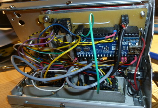
- DLO138_ILI9341_SPI_backside.JPG (61.74 KiB) Viewed 1155 times
[mausi_mick – Mon Nov 20, 2017 4:17 pm] –
Now I have tested an quadencoder on an Namiki motor, the phase difference is 90°
Nive work ![]()
I’ve got some DSO150 to try them out. It works great but only one channel is not very nice ![]()
I’m thinking about making a similar approach but using the F303 and getting to 10MSPS/channel.
I’m going to try changing the F103 for the F303 on a bluepill to test it (like ThunderOwl did ![]() ).
).
Maybe it could be possible to use this code with that chip…
Could you please share the updated schematic for dso?
I want to give a try on this.
here the code,
I used Arduino IDE 1.8.4
- DLO-138-MaMi_05.7z
- (25.16 KiB) Downloaded 208 times
The pcb is hand – made with a small carpet knife.
I realized the two pre-amplifiers with 2 MCP6S91 PGA’s similar like this schematic:
https://jasmedia2011.files.wordpress.co … 472321.png
The used pins of the maple-mini you can see in “global.h” of the last zip-file DLO-138-MaMi_05.
I used 2 spi,
the first for the display ILI9341,
the second spi for the PGA’s / MCP6S91 and the DAC’s MCP4822 .
Not solved is the triggering.
thank you for this beautiful sharing, a perfect device, even if i can not do it because it is too complex for an amateur like me, maybe in the future … great respect for you and thank you again for sharing, cordially
[mausi_mick – Wed Mar 28, 2018 12:51 pm] –
Not solved is the triggering.
A really cheap way of doing triggering is to use the ADC’s analog watchdog.
For a rising trigger set the low threshold (LTR) to zero and the high threshold (HTR) to the value you want to trigger on (for a falling trigger, set HTR to 4095 and LTR to the trigger value). You can check the AWD flag in the ADC status register (which your code already loads when checking if a conversion is complete) to see if a trigger has occurred. You can even get it to generate an interrupt if you decide to change to capturing samples using DMA in the future.
Keep in mind you’ll have to scale the trigger level you program the AWD registers with to match your OPAMP gain.
It might be worth worth considering moving to a DMA in any case. It actually makes things easier and you’ll be able to avoid the need to write assembler code. Let me know if you want to know how I go about it for my F3 based oscilloscope project.
Are you using this code on a F303?
Do you have arduino ide working on the F303?
I was trying to get a base code working with STM32 HAL but it’s still in it’s early days. I have managed to get ILI9341 working but still haven’t digged into the ADC stuff. On arduino would be a lot easier…
[rexnanet – Mon Apr 16, 2018 5:32 pm] –
Hi dave j,Are you using this code on a F303?
No, I’m developing something from scratch.
Do you have arduino ide working on the F303?
No. I’m using Qt Creator as a development environment and targetting the STM32 LL libraries (rather than the HAL ones which reportedly are a bit buggy). Qt Creator is a better C/C++ IDE than Eclipse and you can get it to deploy code to the device and remotely debug too.
I was trying to get a base code working with STM32 HAL but it’s still in it’s early days. I have managed to get ILI9341 working but still haven’t digged into the ADC stuff.
STM32Cube has some good example code that helped me figure out how to do things. Some MCUs have more/better examples than others – don’t just look at those for the MCU you’re targeting.
On arduino would be a lot easier…
Sadly, I think with libraries it’s a case of simple enough for beginners to understand or flexible enough to do complex things. At least with arduino you can ignore its libraries and use others/code direct to the hardware.
Let me know if you want me to describe the approach I’m taking to capturing and triggering.
[rexnanet – Mon Apr 16, 2018 5:32 pm] –
Are you using this code on a F303?
Do you have arduino ide working on the F303?
I was trying to get a base code working with STM32 HAL but it’s still in it’s early days. I have managed to get ILI9341 working but still haven’t digged into the ADC stuff. On arduino would be a lot easier…
I want to make an F303-based oscilloscope, too. I am thinking: two channels, 10M samples/sec (by DMA and interleaving). So far I have an F303 board (by replacing the F103 on a “blue” pill with an F303) and a working stm32generic Arduino core fork.
I am wondering if I should start from scratch or with the DLO-138 source code.
Another possibility would be to buy a DSO-138, transplant an F303 to it (hopefully without breaking anything), and then work on the software.
Any thoughts?
I’m thinking on using the DLO-138 as a starting point and if it’s not viable then try to use STM32-HAL or something. But using DLO-138 would give a nice head start and having a “working” arduino core makes it even more simple ![]()
I’ve also swapped the F103 for an F303 on a blue pill. Swapping it on a DSO-138 or even on a DSO-150, as I’ve thought, it’s no good because of the single analog channel.
I’m thinking about making myself a pcb to get everything together.
The pig-o-scope code is not particularly feature rich but might make a good basic platform to start from.
[rexnanet – Thu May 17, 2018 1:28 pm] –
My plans are the same
I’m thinking on using the DLO-138 as a starting point and if it’s not viable then try to use STM32-HAL or something. But using DLO-138 would give a nice head start and having a “working” arduino core makes it even more simple
I guess it comes down to how different do you want your scope’s UI to be from that provided by DLO-138.
I’ve also swapped the F103 for an F303 on a blue pill. Swapping it on a DSO-138 or even on a DSO-150, as I’ve thought, it’s no good because of the single analog channel.
I’m thinking about making myself a pcb to get everything together.
How many of the other F303 peripherals, e.g. built in OPAMPs and comparators, do you envisage using? That could drastically affect which pins you can use for things like screens, buttons, etc.
I found STM32CubeMX is a good way of trying different combinations of peripheral and pin assignments with it warning you of incompatible combinations.
[arpruss – Fri May 18, 2018 6:25 pm] –
I’m thinking of using my phone for a screen, at least for initial testing, which will save some pins. An advantage is that the phone can also power the board. I’m currently writing an Android app that functions as a vector display for an Arduino sketch, via USB serial.
Interesting..
Did you write the App?
I found that Android didn’t recognise the VID PID of leadlabs CDCACM , last time I tried it . ( but that was years ago, so things may have changed)
[RogerClark – Fri May 18, 2018 11:58 pm] –
Interesting..Did you write the App?
It’s in progress here: https://github.com/arpruss/vectordisplay (see the VectorDisplay example; the library I’m using for serial comm isn’t mine).
It seems to work fine with the product and vendor id that STM32GENERIC uses by default. I haven’t tried it with the LeafLabs one.
I found that Android didn’t recognise the VID PID of leadlabs CDCACM , last time I tried it . ( but that was years ago, so things may have changed)
I found that some Android serial libraries didn’t recognize the device, but the one I ended up using recognizes it just fine.
The tentative Arduino side is here: http://github.com/arpruss/vectordisplayarduino , but I expect the API will change.
I’m trying to use a mcufriend display (which works fine on Arduino Mega2560 and returns the ID code 0x154),
But even without the display, when I look at the state of the pin with an LED and an oscilloscope, I noticed that the PB3 bit is floating.
The strange thing is that the original firmware of the DSO150 does not leave the PB3 pin floating, the LED can light (and blink) and the oscilloscope shows pulses.
What could be happening?
I have 2 bluepill, and both show the PB3 pin floating.
I had to disable the JTAG of this PB3 pin:
I added the instruction below at the beginning of the subroutine “setup”
afio_cfg_debug_ports(AFIO_DEBUG_NONE);
With the help of Sr. David (from https://github.com/prenticedavid) I was able to modify the Adafruit_TFTLCD_8bit_STM32 library for MCUFRIEND_kbv.
The code has been stored here (because this site – stm32duino – does not allow the file size):
https://github.com/ardyesp/DLO-138/issues/10
P.S.: The mcufriend library supports many display models, it may be cool to use this library instead of others, since the support is exceptional!
10. It currently supports UNO shields with "mcufriend.com" pcbs with controllers:

HX8347-A 240x320  ID=0x8347 #define SUPPORT_8347A *** Untested ***

HX8347-D 240x320  ID=0x4747 #define SUPPORT_8347D

HX8347-G 240x320  ID=0x7575 #define SUPPORT_8347D

HX8347-I 240x320  ID=0x9595 #define SUPPORT_8347D

HX8352-A 240x400  ID=0x5252 #define SUPPORT_8352A

HX8352-B 240x400  ID=0x0065 #define SUPPORT_8352B

HX8357-B 320x480  ID=0x8357 (shares init with 8357-D)

HX8357-C 320x480  ID=0x9090 (ID has changed from 0x8357)

HX8357-D 320x480  ID=0x0099 #define SUPPORT_8357D_GAMMA

HX8367-A 240x320  ID=0x6767 #define SUPPORT_8347D

ILI9225  176x220  ID=0x9225 #define SUPPORT_9225

ILI9226  176x220  ID=0x9226 #define SUPPORT_9225

ILI9302  240x320  ID=0x9302

ILI9320  240x320  ID=0x9320

ILI9325  240x320  ID=0x9325

ILI9326  240x400  ID=0x9326 #define SUPPORT_9326_5420

ILI9327  240x400  ID=0x9327

ILI9328  240x320  ID=0x9328

ILI9329  240x320  ID=0x9329

ILI9331  240x320  ID=0x9331

ILI9335  240x320  ID=0x9335

ILI9338  240x320  ID=0x9338

ILI9340  240x320  ID=0x9340

ILI9341  240x320  ID=0x9341

ILI9342  320x240  ID=0x9342 #define SUPPORT_9342

ILI9481  320x480  ID=0x9481

ILI9486  320x480  ID=0x9486

ILI9487  320x480  ID=0x9487

ILI9488  320x480  ID=0x9488 (weird 555 display :#define SUPPORT_9488_555)

LGDP4532 240x320  ID=0x4532 #define SUPPORT_4532

LGDP4535 240x320  ID=0x4535 #define SUPPORT_4535

NT35310  320x480  ID=0x5310 (hardware must be set for 8-bit parallel)

R61505   240x320  ID=0x1505 works like an ILI9320

R61505V  240x320  ID=0xB505

R61505W  240x320  ID=0xC505

R61509V  240x400  ID=0xB509 #define SUPPORT_B509_7793

R61520   240x320  ID=0x1520 (no Vertical Scroll)

R61526A  240x320  ID=0x1526 (no Vertical Scroll) configure NVM with sketch

R61580   240x320  ID=0x1580 #define SUPPORT_1580 *** Untested ***

R61581   320x480  ID=0x1581

RM68090  240x320  ID=0x6809

RM68140  320x480  ID=0x6814 #define SUPPORT_68140

S6D0139  240x320  ID=0x0139 #define SUPPORT_0139 (no Band Scroll)

S6D0154  240x320  ID=0x0154 #define SUPPORT_0154

SPFD5408 240x320  ID=0x5408

SPFD5420 240x400  ID=0x5420 #define SUPPORT_9326_5420

SSD1963  800x480  ID=0x1963

SSD1289  240x320  ID=0x1289 #define SUPPORT_1289

ST7781   240x320  ID=0x7783 #define SUPPORT_7781 (no Vertical Scroll)

ST7789V  240x320  ID=0x7789

ST7793   240x400  ID=0x7793 #define SUPPORT_B509_7793

ST7796   320x480  ID=0x7796

UC8230   240x320  ID=0x8230 #define SUPPORT_8230

UNKNOWN  320x480  ID=0x1511 (scroll directions not correct)

UNKNOWN  240x320  ID=0x1602

UNKNOWN  240x320  ID=0xAC11

UNKNOWN  240x320  ID=0x2053 weird controller from BangGood (was ID=0x0000)

UNKNOWN 240x320 ID=0x8031 (no Vertical Scroll)
I’ve been trying to assemble this oscilloscope. I’m particularly interested in the second channel addition, so I’m going through the whole hardware modification. I had an old DSO138 I burned laying around, so I reused the usable components and designed a pcb focusing on making it easy to make at home. I tried to get all the hardware in one pcb where I can kind of plug the DSO138 on top as kind of a shield (with some modifications I haven’t made yet). The pin locations and basically every connection there is between the usual DSO and the new DLO maps from my shield into the DSO, leaving the taller components or those that need to stay accesible (switches, encoder…) out of the DSO outline. I’m not sure all these single pin connections are going to be possible to make in a “shield” kind of setting, but I’m trying. It’s still untested so use at your own risk.
I would have branched/forked/pulled this into the ardyesp github, but I have no idea how to use github and I haven’t had the time to learn, but here you have the eagle files: https://github.com/Damrod/DLO-board
There’s anyhow something I’m struggling to understand from the schematics, so I don’t think I can properly render it in my pcb: the “D CH1” “D CH2″… do they map into some connection os is it just informational? Is it like the encoder label that maps the way I mapped it or…? I attached an image to indicate this question.


