Is there any direct support for this MCU?
Maybe some feature missing, but just tell us which ones …
1. If you are doing any flying things, the BetaFlight can be modified for your needs. For most cases, only minor changes are required. As the BetaFlight is based on the ST HAL library, there are a lot of related libraries and documentations available.
2. ST has been working with STM32duino and made the HAL libraries available for many STM32 Nucleo and Disco boards. As such, they can be used with Arduino IDE.
3. STM32duino has its own F4 support. The main target has been F407.
Related to this F405 board, I can observe that it is quite expensive compared to the classic style of boards. On the higher side, it has a limited performance compared to F745 board used in AnyFC-F7. With $30 you can get more connectivity, higher performance, and built-in IMU and still use the same BetaFlight library as used with F405. Many of these advantages are the fruits from the OpenPilot project done during the past years.
It is also quite expensive.
So IMHO only if use if you need a small powerful board but don’t need many GPIOs
The connectors are made to connect servos so it could be used e.g. for a little robot.
http://www.stm32duino.com/viewtopic.php?f=39&t=1977
one of those tiny F407VE boards i got are these
http://www.stm32duino.com/viewtopic.php … =10#p26277
http://www.stm32duino.com/viewtopic.php … =40#p27327
at about 2x the breadth of BP/MM 4cmx5cm it qualifies as a ‘tiny’ board with all the pins broken out and has an on board uSD card slot + on board crystals
then there are some other worthy competitors that are discussed in the thread
among them this board from olimex is pretty compact and decently priced
https://www.olimex.com/Products/ARM/ST/STM32-H405/
and you may also want to take a look at those micropython f405 boards which are true challengers in the ‘tiny’ arena who makes tiny f405 boards with as many pins broken out as is possible. micropython also throws in a 3 axis accelerometer MMA7660 on board and an ultra compact uSD card slot on a really tiny form factor
https://store.micropython.org/store/
https://www.aliexpress.com/item/Mini-ve … fbb0123c5e
It’s really small (50x40mm) but includes an i2c eeprom, and sdcard slot, and all MCU pins broken out.
I have still not used it, but plan to use it for my marlin tests.
[victor_pv – Thu Jul 27, 2017 3:58 pm] –
Just for reference, I recently bought one of these:
I have still not used it, but plan to use it for my marlin tests.
What is the tiny voltage reg there on the board?
http://www.stm32duino.com/viewtopic.php … 390#p31985
That regulator may work up to 200-250mA with 3.6-3.8V input.
For example:
P = (3.8V -3.3V ) * 0.25A = 125mW, the chip temp at ambient temp will be:
T = 0.125W * 250degC/W + 25degC = 31.25degC + 25degC = 56degC (hmm, you will burn your finger)
The problem of the chip used is its package – the thermal resistance (250degC/W) is so high, that that chip
catches fire. The larger 1117 reg package on other boards gets something like 60degC/W so the chip would be 33degC (with those 125mW) at ambient temp.
http://www.richtek.com/assets/product_f … 193-16.pdf
it would seem to me that its attractiveness is the 220mv dropout voltage, this would make it feasible to feed a 4.2v LiPO battery into the 5v lines, and there is sufficient headroom 4.2 – 0.22 ~ 3.9v to keep running off a single charge till around 2v. a lm1117 or ams1117 has a 1v dropout which would be ok for 5v but with 4.2v that leaves 3.2v at the stm32 even when fully charged
but i’d guess f4 being more power hungry vs f103, i’m not sure if we could or if it make sense to swap the on board LDO for a ams1117 or lm1117 when running off 5v
in addition i’m not sure if there is after all a feasible way to cool a sot23 ldo with a heatsink etc
![]()
[Pito – Thu Jul 27, 2017 10:30 pm] –
The problem of the chip used is its package – the thermal resistance (250degC/W) is so high, that that chip
catches fire. The larger 1117 reg package on other boards gets something like 60degC/W so the chip would be 33degC (with those 125mW) at ambient temp.
Thanks for the warning, I’ll feed it with 3.3V from another regulator.
Note: below calculations are simplified calculations. The precise modeling usually requires to consider about 6 thermal resistances (serial/parallel) placed along the thermal path from the chip up to heatsink’s fins, material properties, airflow and geometry.
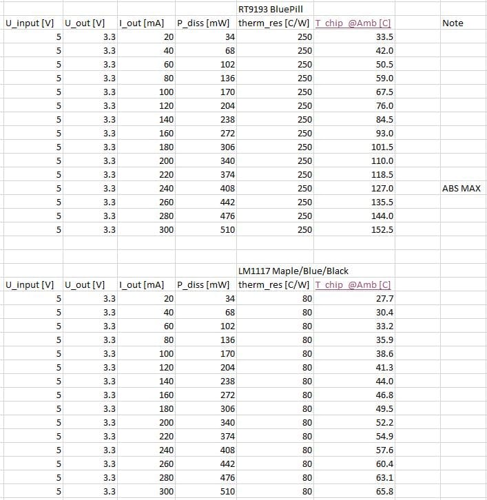
- Voltage Regulators Imax and Temp.JPG (101.22 KiB) Viewed 616 times
https://www.ebay.com/sch/i.html?_from=R … r&_sacat=0
stick that with some thermal compound to the sot23 LDOs, then perhaps run some benchmarks or some heavy gpio processing on stm32f4 (it may be even more fun if it is overclocked)
that’d give a feel of just how much heat gets generated (at least the termperature), but then the thermistor leads would likely conduct away some heat as well
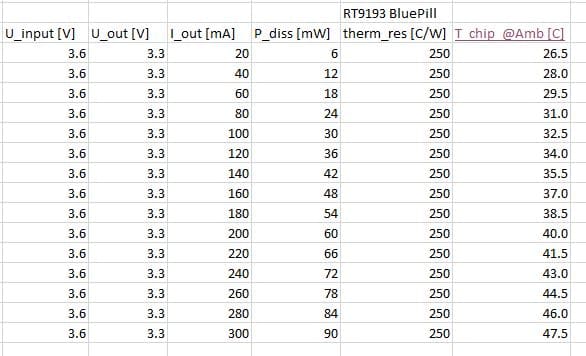
- Voltage Regulators Imax and Temp 36.JPG (51.4 KiB) Viewed 611 times
https://en.wikipedia.org/wiki/Thermal_resistance
From Fourier’s Law for heat conduction, the following equation can be derived, and is valid as long as all of the parameters (x and k) are constant throughout the sample.
R = x / ( A * k )
where:
R is the absolute thermal resistance (across the length of the material) (K/W)
x is the length of the material (measured on a path parallel to the heat flow) (m)
k is the thermal conductivity of the material (W/(K·m))
A is the cross-sectional area (perpendicular to the path of heat flow) (m2)
this would seem to imply that the rather high thermal resistance is partly due to the small size, hence small A, assuming that there isn’t any way to influence x and k.
this may somehow mean that if there is some ways to ‘heatsink’ that sot23 LDO, we may literally reduce the thermal resistance (and possibly significantly), this could for instance be possible by using some heatsink thermal compounds, but it would also mean attaching a heatsink so that all that heat is conducted away and dissipated over a (much) larger area.
the obvious problem is that it’d seem quite difficult to heatsink that sot23 LDO, as it would seem otherwise the LDO may possibly be able to handle higher currents than specs suggests. but on top of thermal problems, the MOSFET transistors used in the LDO may have actual electrical limits e.g. the minimum on resistance at the current voltages, that’d probably mean that beyond 300mA, the voltage dropout would be limited by the MOSFET on resistance and loses its ability to supply the desired voltages e.g.< 3.3v
http://www.ti.com/lit/ds/symlink/tps82130.pdf
Up to 17V input, 3A output, 2MHz, 90% eff at 1A, with integrated inductor, 3.0×2.8mm package.
Maybe it could be a good replacement.. ![]()
[ag123 – Fri Jul 28, 2017 4:40 pm] –
this may somehow mean that if there is some ways to ‘heatsink’ that sot23 LDO, we may literally reduce the thermal resistance (and possibly significantly), this could for instance be possible by using some heatsink thermal compounds, but it would also mean attaching a heatsink so that all that heat is conducted away and dissipated over a (much) larger area.
increasing the pcb copper area for the LDO is not possible.
cringe if you wish, lift the tab insert copper plate and resolder both to original copper pad ![]()
otherwise lift the LDO and use 3 wires to another regulator with a heatsink appropriately mounted
srp
Take a piece of wire, ie. 0.4-0.6mm dia, make a small coil from it, say 4-5windings 2mm dia, solder the short leads to pins 1 and 3 (Vin, En) such the coil touches the top of the package. Apply a small dot of glue or (none conducting) thermal paste beneath the coil such it gets better thermal contact to the package. It will cool down the chip via pins 1 and 3 as well as via the top of the package. Not to scale:
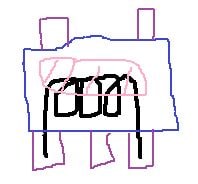
- 9193 cooler.JPG (14.8 KiB) Viewed 750 times
With 2x 33ohm in parallel the Iout aprox 220mA, and you cannot touch the package anymore, crazy hot!
Would be great if somebody could measure the temperatures and verify the tables above.
Btw, the fundamental laws of physics are not easy to bypass as of today, the thermal power dissipated by any linear voltage regulator is simply
P = (Uin – Uout) * (Iout + Ireg), [W, V, A], where Ireg could be neglected with modern regs.
[Pito – Sun Jul 30, 2017 11:43 am] –
…you can keep touching with your finger till about 50degC with a standard human…
That is for a metric calibrated human finger. Those of you in the land of Trumpentweet will have fingers pre-calibrated to 122 F ![]()
[ahull – Sun Jul 30, 2017 1:15 pm] –[Pito – Sun Jul 30, 2017 11:43 am] –
…you can keep touching with your finger till about 50degC with a standard human…That is for a metric calibrated human finger. Those of you in the land of Trumpentweet will have fingers pre-calibrated to 122 F

Those of us have such a thick skin by now that our fingers will probably burn before we notice…
[victor_pv – Sun Jul 30, 2017 1:28 pm] –[ahull – Sun Jul 30, 2017 1:15 pm] –[Pito – Sun Jul 30, 2017 11:43 am] –
…you can keep touching with your finger till about 50degC with a standard human…That is for a metric calibrated human finger. Those of you in the land of Trumpentweet will have fingers pre-calibrated to 122 F
Those of us have such a thick skin by now that our fingers will probably burn before we notice…
.. in which case, a keen sense of smell will be needed to determine if the finger is rare, medium or well done.
Spit at the voltage regulator, and when
– the water boils and evaporates within 3 seconds – the temp is >= 110degC
– you see dancing balls – the temp is >= 210degC
You also may spit at your finger and when it sizzles when touching the regulator the temp will be >=110degC.
The people with musical ear may distinguish the temperature ranges based on the sizzle’s pitch ![]()
Use at your own risk, no warranties of any kind..
![]()
![]()
It has also a ESP8266 as WIFI interface.
I wonder if it would be complicated to get the thing running.
http://www.intorobot.com/downloads/manu … eet_En.pdf
Shame there is no schematic
[ChrisMicro – Tue Aug 29, 2017 6:10 am] –
I wonder if it would be complicated to get the thing running.
It should not, although without schematics, some pain can be faced …

