This Thread will be used for updates
Hello ![]()
In a different topic a user (madias) had the idea of an community board and i kinda want to make it ![]() I would really like it if someone could suggest some features it should have. Im gonna list everything i have in mind:
I would really like it if someone could suggest some features it should have. Im gonna list everything i have in mind:
- usb-serial chip (ch340?)
- i2c pullup with jumpers (4k7)
- onewire output with pullup?
- Some onboard stuff, not quite sure yet. Maybe button, leds, pots etc.
- boot select
- usb-connector(micro/mini?) for host-function
- reset
- external power?
- screen (bl being driven by transistor for pwming)
- 8mhz ex. crystal(bcs i’ve seen it on any other board) + rtc crytal
- dallas temp sensor(ds18b20)
- micro sd card slot
- dedicaded ports for 5v -> 3.3v logic conversion
- small formfactor, around 5x5cm (def. wont work at the end xD )
For the display i’d like to try to get a graphics library running on it, would like to get ucglib running
You can also tell your opinion about my ideas.
As soon as i have a shematic, im going to post it here. Everything is going to be creative common of course ![]()
~Straw
-have it have Arduino headers, to be able to plug existing shields, and unless the Maple pin map had any trouble, just use the same, or otherwise use two rows like the mini. Arduino headers fit in a 5×5 board but you may need something bigger if you include many things on it.
-A micro USB connector. All the new phones come with those, so plenty of cables and power adapters laying around with that connector.
-External power, yes, and one that can take at least 9V with some load, not the crap in the original mini. Perhaps a second regulator for the ADC plane like the original mini had.
For 5 to 3V conversion I have used NVT2008PW with good results, although there may be cheaper options around. the TSSOP package is also easy to solder with an iron.
Everything else that you list sounds like nice features to have.
Board size:
Not a further “mini clone” again.
As I posted before, there are good conditions for following formats: 50mmx50mm and 100mm x100mm. Look at dirtypcbs.com (have ordered successfully 10 pcs 100×100 boards, looks really good! (get 12 pcs!)): 10 each 5x5cm PCBs $14 • 10 each 10x10cm PCBs $25. Every other size is really expensive!
With a 100×100 size board you can get really cool stuff “on board”: pin headers for an ILI9341 (problem! how much inches?), rows of pin headers for: 3.3V, 5V, GND, SPI1+2, I2C1+2,…
Maybe all breakout pins as double row (choice able: female and/or male), spacers for flash rom chips (winbond…), pinouts for SD-card, user buttons and LED`s, (jumper able), spacer for I2s audio DAC (they are sooo cheap with good quality!)
MCU:
victor hit it: STM32F103RGT6! 96kB RAM, 1MB Flash, 5x USART, 3x SPI, 2x I2c, 2x I2S.
Ok, this would be a complete “multimedia board”
Drawback: This board is definitely “harder” to solder for beginner because of SMD parts. LQFP64 should be possible, for other parts (resistors, caps) I would prefer 0805 size.
What price range are you shooting for?
I have used dirtypcbs and iteadstudio(even cheaper for 10×10 boards). You get 10 pcbs for 15 bucks, so that $1.5 per pcb.
MCU perhaps $5, add headers, discrete components, perhaps another $5-10.
you get a board for under 20 with more options than a nucleo, and way more than a maple mini.
Rather than plugging a bunch of things with wires to the mini, you get the common ones on the PCB. If you want solder them, if you dont need a flash memory, dont solder it. If you dont need a micro-sd slot, dont solder it.
The price of the PCB depends only on size, you can load it with components on both sides and only solder whatever you need. So you end up with 1 single board design, that fits a few different options, for the same price as a Nucleo or one of the Chinese RET boards (and some work of course).
On top, having a common board means we all can contribute to code that works for everyone, rather than each one fixing code for his board.
I have been waiting for Guinessimo to release his design, that he posted about in the arduino forum, but I think he is still working on his final version.
For the bare minimum, I dont think there is any way to beat a $4 maple mini.
The china ones (they are not clones at all!) are by-products from commercial designs (So I guess it) made for special use.
The nucleos on the other side are strange: Super cheap and not intelligent designed: Useless “arduino style headers” with not compatible pins (I try/tried to manage the nucleo F103RB variant) as marketing gag (to be honest: who is using “arduino shields anymore?). The best part of them is the ST-Link 2.1. (I use it for other boards). Another drawback: You are not allowed to use nucleo boards in any commercial kind.
So a really “cliffhanger” would be: I2s Audio DAC’s, flash ram, SD-Card holder and TFT connectors.
So the “community board” should be really tinker friendly with enough pin rows/jumpers. I don’t know how much a “ready to go” board would cost. So the first step would be only the pcb (2.5 USD/pcs, but you get at least 12 pcs), the other parts can be easily ordered from ebay or ali. Second step for a bigger number of boards can be a kickstarter campaign.
So all in all the PCB only variant with all parts would cost about 10-30USD /pcs (depends on MCU/equipment). keep in mind, that you have to take 12 at least for the PCB and you have to solder it yourself.
Ok: One thing, I forgot: ST-Link connector! So we avoid any bootloader or secondary chip and let us up the possibility of debugging in the future.
Im searching all the parts now and post the price per board here.
~Straw
EDIT: No, its not going to be Maple Mini sized ![]()
It is my opinion that the core simply is not ready for such an event. While the bulk of stuff works, there are still some rough edges in using all of the embedded hardware capabilities on the STM32F103. A kickstarter campaign would simply throw a crowd of eager tinkerers into the forum and drive Roger and the other contributors to distraction and divorce.
IMO, an open source project such as this should take the high-road and utilize existing hardware. This is not to say that those capable of creating their own boards should not, not by any means – maybe bartering around in the forum to existing members or selling for cost+… something like the Bobduino 1284. But Kickstarter would seem to be a major leap IMO and would require control of both the hardware design and the software integration. Then there is the entire layer of customer service, support, etc.
Ray
A community board would be neat, but there are too many priorities for 1 board to satisfy all. Even Leaf Labs had a Maple and Maple mini. I personally could have uses for a small board which is already available in STM32F103CB and STM32F103C8 forms quite cheap. I could also see myself looking at some of the discovery STM32F4 boards for some larger projects.
Then there are the questions of power requirements. You can get LM1117/AMS1117 voltage regulators very cheap, but they have a quite large 5-10mA Quiescent Current, making them unsuitable for battery powered devices.
By all means, I think some community designed plans would be cool, but I wouldn’t suggest bending over backwards to try and satisfy everyone (I won’t even start to think about Arduino rookies that may want full shield compatibility and ability to run their 5V I/O shields without understanding that ARM chips are strictly 3.3V).
~Straw
A community board would be neat, but there are too many priorities for 1 board to satisfy all. Even Leaf Labs had a Maple and Maple mini. I personally could have uses for a small board which is already available in STM32F103CB and STM32F103C8 forms quite cheap. I could also see myself looking at some of the discovery STM32F4 boards for some larger projects.
Then there are the questions of power requirements. You can get LM1117/AMS1117 voltage regulators very cheap, but they have a quite large 5-10mA Quiescent Current, making them unsuitable for battery powered devices.
By all means, I think some community designed plans would be cool, but I wouldn’t suggest bending over backwards to try and satisfy everyone (I won’t even start to think about Arduino rookies that may want full shield compatibility and ability to run their 5V I/O shields without understanding that ARM chips are strictly 3.3V).
I personally have not had a micro USB fail in any device ever, but I tend to be careful with things.
In any case a design on KiCad or Eagle can be easily customized by someone that wants to change the connector type, as both of them have almost the same size and are SMD, there shouldn’t be any problem in making the design with one and changing it later if needed without a big rework.
I totally support Madias idea on adding an ST_link header, probably best with the small 6 pin one used by the nucleo boards rather than the larger 10 pin one.
About voltage regulators, I am sure there are better ones than the 1117 if we need to reduce consumption. I believe I reather a recommendation for one in particular in the leaflabs forums, I’ll see if I can find that post.
Pinout is compatible with the AMS/LM 1117, and quiescent current is only 60 to 90 uA for the 3.3 part.
Datasheet:
http://www.mouser.com/ds/2/115/AP2114-271472.pdf
So the board can be designed with the AMS1117, and if someone needs lower quiescent current, use that part rather than the 1117.
Current limit is lower, at 1A, but I doubt someone needs to shave 10mA at the same time he needs to consume more than 1 amp total.
Price per unit is $0.40 for 1 unit from mouser, cheaper on bigger quantities, but cheap enough in small quantities to not be a problem.
I am sure there can be better options, that was just the first one I saw with 1117 pinout, high output current, and low quiescent.
I personally have not had a micro USB fail in any device ever, but I tend to be careful with things.
In any case a design on KiCad or Eagle can be easily customized by someone that wants to change the connector type, as both of them have almost the same size and are SMD, there shouldn’t be any problem in making the design with one and changing it later if needed without a big rework.
I totally support Madias idea on adding an ST_link header, probably best with the small 6 pin one used by the nucleo boards rather than the larger 10 pin one.
About voltage regulators, I am sure there are better ones than the 1117 if we need to reduce consumption. I believe I reather a recommendation for one in particular in the leaflabs forums, I’ll see if I can find that post.
BTW. Is there any need for a full sized JTAG connector?
~Straw
The user guide is here if you want to check anything else:
http://www.st.com/st-web-ui/static/acti … 105823.pdf
The pinout is like this:
1 VDD_TARGET: VDD from the application. (I dont normally need to connect this, the st-link powers itself)
2 SWCLK: SWD clock
3 GND: Ground
4 SWDIO: SWD data input/output
5 NRST: RESET of target MCU
6 SWO: Reserved
The MCU datasheet should show to which pin each of those go. In the maple mini they are the pins between 18 and 22, but I’ll see if I can find them in the RET datasheet and post it.
I have placed an order for 1, although I suspect I won’t receive what I should and will need to open a case with Aliexpress, but even if I get 10x RET, or just 3 or 4 RGT, still would be a good deal.
And check the stm32f103rft6 I see tons of vendors selling that one for around $30 for 10 of them. I am not sure where all those cheap chips may come from, perhaps left overs from some production runs? or just faulty chips being resold…
Man, i really need to look at all those stm32rxxx chips before beginning the schematic
Guess those chips are so cheap because they buy them in huge bulk and use them either for dev boards or other things and sell some of them.
~Straw
~Straw
Anyway I’ll have a look at the datasheet later to see if the pinout is exactly the same in all 3 of them, and confirm.
I’ll let you know when the RGTs ships, and hopefully if/when they arrive
I think if the seller is legit, it won’t have stock at that price for long though. I think is most likely just a price mistake and should show 1 per lot at that price…
Even the maple mini is an incredible value at $4 shipped to your door… I wonder how cheap can they get the components to produce the board and then ship that to you at $4 and still make a profit…
~Straw
~Straw
For example, I have a CH340 USB to RS485 dongle, it is reported as :
Bus 002 Device 068: ID 1a86:7523 QinHeng Electronics HL-340 USB-Serial adapter
~Straw
Also, they are cheap : you can get 10x chips for less than $6 …
~Straw
Pinheader for 2.2 2.4 2.6 ILI touch TFT (we HAVE a superb DMA/SPI driver within the standard library! )
So there would be a “common” layout with the basics (predefined MCU, ST-link, maybe usb/serial chip, FlashRAM,Audio DAC(?),….) and the rest is up to the user.
I’m not sure how any people need 1Mb of Flash for their sketch or even 512 or perhaps even 256k of flash.
Because when you get to that size of Flash, you are probably trying to store images or sounds in the flash, and compiling in large external files is in my experience quite slow, as its not what the compiler is designed to do.
You are better off an external SD card for storage of that sort of stuff.
Even the 128k of Flash in the F103CB is massive when compared with the Uno.
The one benefit of the F103RC , RE RF and RG is that you get 2 DAC’s and also more RAM. I can see that for some people that 64k or even 96k of RAM would be really useful, e.g. processing sound from a microphone or still images from a camera.
The sweet spot is probably still the F103RET or RDT, as both have 64k of RAM.
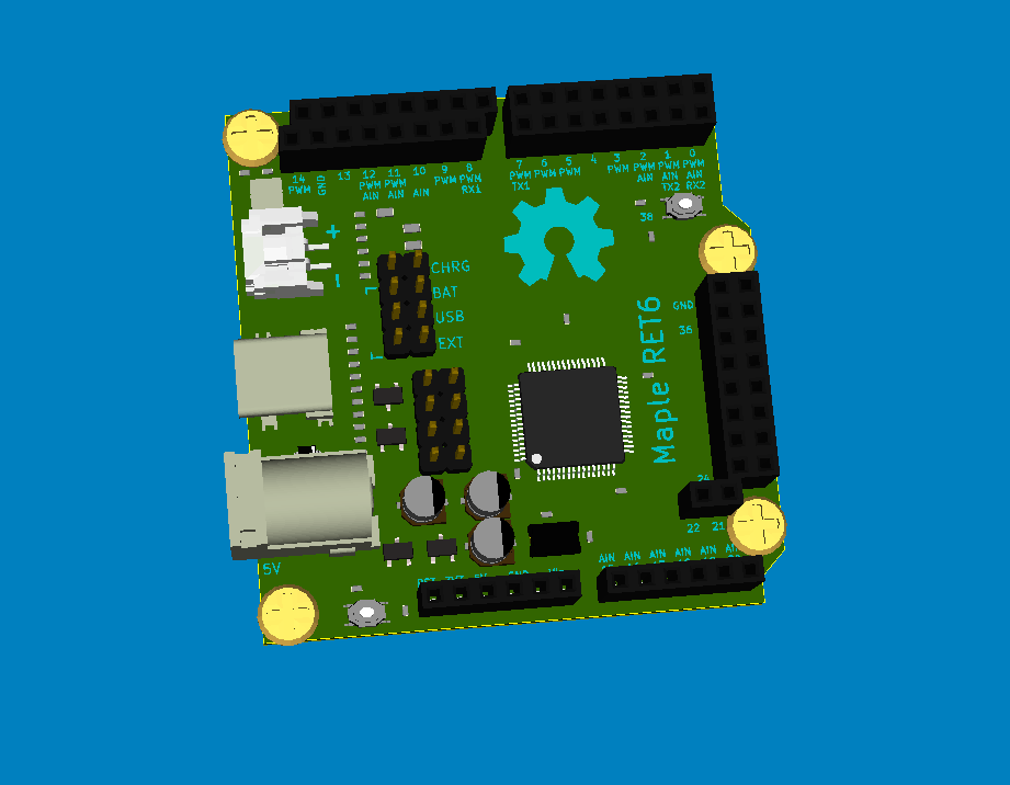
As has been pointed out, designs exist for the Maple RET6, and I know @skyng22003 has made one of those himself, so he’s probably the best person to comment.
iTeadStudio did an updated Maple Rev 3 which looks like its a newer design, and would also be worth looking at, apart from they use a RBT not an RET ![]()
They are currently charging $13 for their RBT board
Anyway, unless it could be made in China, the price is going to be uneconomically high.
But PCB’s could be made cheaply, so perhaps thats one option, i.e do a batch of Maple RET 6 PCB’s and get some F103RETs
Re: On board USB to Serial
I’m not sure there is much point in this.
just connecting the USB to Serial device to HW Serial 1 won’t do an upload unless Boot0 is HIGH, and although several people have tried hacks to get DRT or CTS etc to control reset and Boot0, its not reliable across all platforms.
The method that LeafLabs (and other people use) of having hardware to reset the USB bus, to force re-enumeration, actually now works really well.
So as long as there are no nasty surprises in Windows 10, this still seems like the best option to me.
PS. It may be possible to use GPIO lines some of the more expensive USB to Serial chips, but they end up being more expensive than just doing what the STM Nucleo and STM Discovery boards use, which is a cheap STM32F103C8 to handle the comms with the PC.
Going forward, I can also see that STLink or Black magic probe will probably come to prominence, because of the ability to do in circuit debugging.
So whatever board gets designed it needs to support this eve if its via an external SWD connector.
As Roger pointed out the RET6 is probably the sweet spot.
I don’t think developing the board for something lower in the series would be worth it. If it is going to take time and effort, it needs to be better than what we have around.
One other option we have is asking iteadstudio for a version of their maple with the RET6.
Or once we have a design, if there is a enough people interested, we can ask one of the Chinese factories to do a short run, although I have no experience with that and don’t know what is their minimal run to be competitive in price.
~Straw
Also, both dirtypcbs and elecrow took a design that included 3 boards in a single design, and did not charge any extra. The boards were attached to each other by small channels.
Unless you go real crazy with tiny SMD components, I don’t think it would be a problem for most people.
An option I have seen before in some community run pcbs, is to order the boards from china with the SMD components soldered.
I believe both elecrow and iteadstudio can provide a quote for that, if the run is big enough (could be in the order of 100 boards, from an example quote elecrow has posted in their website, but they may do smaller quantities).
I will really enjoy building it completely, but if more people with less knowledge is interested, ordering a batch with preassembled SMD parts is an option.
And ATM its just a board with direct pinout for everything and just a few things onboard.
~Straw

But i think the only thing that could be different is die chip size.
~Straw
That page is from a doc about the smaller devices, as it doesn’t show the memory sizes for the RC RD RE RF and RG devices.
Nevertheless I think you are correct, because the R is the device package size.
So if the board was designed for an R series device, it would accept all those variants.
Seriously though…
Can people give an indication of what they would pay for an assembled board ?
I paid $13 for the iTeadMaple board, but it only has a RB chip on it, so although build quality is excellent, I think is not as good value as the generics there you can get a F103VET board for a similar amount.
How much is a UNO clone ?
I guess people would pay a few dollars more for a Maple Ret 6
Btw. It may need to be called some other name, not Maple, but I guess all the Leaflabs stuff is in the public domain, so the name can’t be trademarked in this area
How much is a UNO clone ?
-RET6
-Pinout of SPI, I2C, I2S, UART, ADC, DAC, And one more for General purpose
-(micro)SD Card slot (not Quite sure which one)
-CH340G Serial converter
-2 Mini/Micro USB (Host&Serial)
-6Pin StlinkStlink
-10 Pin SWD
-Boot0/1 jumper
-reset button
-PWM Pins With transistors & external power source (LEDs f.ex)
-some Buttons, LEDs (still searching nice pots)
-Direct port for 2.2inch ili9341 Screen
-CR2032 socket for RTC
(-7 segment display)
(-eeprom)
(-mpu6050 port)
(-esp8266 port)
Still finding a solution for not using the same pin for 2 things( like trying to use UART and ADC)
I thought to limit the usage of some Pins (who needs 5 Serial connections anyway) but that wouldnt be the right solution.
I dont know any Name for it. Used stmBerry and stm32berry AS Working title for the eagle library and project xD
~Straw
LONG EDIT:
The price above is prob. Not complete assembled price. Short list oft things i can remeber the price oft:
Ret6 2.4€
-Serial converter 40cent
-SD card holder 10cent
-PCB 2.5$ (dient had time looking for other services )
-USB 10 Cent
So well, i think no one would say anything against the price. But another solution would be to plan it With more onboard stuff (LED, cap touch Sensor, light Sensor, RGB led, stepper driver) and simply not populate what isnt needed. So that someone can get it With just the chip and regulator but still has the Chance to use a much better pinout which tells you what it does. But ill neee to Jeep that in mind that it should work in this minimal layout.
~Straw
~Straw
~Straw
http://manpages.ubuntu.com/manpages/ut … ash.1.html
NAME
stm32flash – UART flashing utility for STM32 and STM32W
SYNOPSIS
stm32flash [-cfhjkouv] [-b baud_rate] [-m serial_mode] [-r filename]
[-w filename] [-e num] [-n count] [-g address] [-s start_page] [-S
address[:length] [-i GPIO_string] tty_device
DESCRIPTION
stm32flash reads or writes the flash memory of STM32 and STM32W.
It requires the STM32[W] to embed a bootloader compliant with ST
application note AN3155. stm32flash uses the serial port tty_device to
interact with the bootloader of STM32[W].
OPTIONS
-b baud_rate
Specify baud rate speed of tty_device. Please notice that the
ST bootloader can automatically detect the baud rate, as
explaned in chapter 2 of AN3155. This option could be required
together with option -c or if following interaction with
bootloader is expected. Default is 57600.
-m mode
Specify the format of UART data. mode is a three characters
long string where each character specifies, in this strict
order, character size, parity and stop bits. The only values
currenly used are 8e1 for standard STM32 bootloader and 8n1 for
standard STM32W bootloader. Default is 8e1.
-r filename
Specify to read the STM32[W] flash and write its content in
filename in raw binary format (see below FORMAT CONVERSION).
-w filename
Specify to write the STM32[W] flash with the content of
filename. File format can be either raw binary or intel hex
(see below FORMAT CONVERSION). The file format is automatically
detected. To by-pass format detection and force binary mode
(e.g. to write an intel hex content in STM32[W] flash), use -f
option.
-u Specify to disable write-protection from STM32[W] flash. The
STM32[W] will be reset after this operation.
-j Enable the flash read-protection.
-k Disable the flash read-protection.
-o Erase only.
-e num Specify to erase only num pages before writing the flash.
Default is to erase the whole flash.
-v Specify to verify flash content after write operation.
-n count
Specify to retry failed writes up to count times. Default is 10
times.
-g address
Specify address to start execution from (0 = flash start).
-s start_page
Specify flash page offset (0 = flash start).
-S address[:length]
Specify start address and optionally length for read/write/erase
operations.
-f Force binary parser while reading file with -w.
-h Show help.
-c Specify to resume the existing UART connection and don’t send
initial INIT sequence to detect baud rate. Baud rate must be
kept the same as the existing connection. This is useful if the
reset fails.
-i GPIO_string
Specify the GPIO sequences on the host to force STM32[W] to
enter and exit bootloader mode. GPIO can either be real GPIO
connected from host to STM32[W] beside the UART connection, or
UART’s modem signals used as GPIO. (See below BOOTLOADER GPIO
SEQUENCE for the format of GPIO_string and further explanation).
BOOTLOADER GPIO SEQUENCE
This feature is currently available on Linux host only.
As explained in ST application note AN2606, after reset the STM32 will
execute either the application program in user flash or the bootloader,
depending on the level applied at specific pins of STM32 during reset.
STM32 bootloader is automatically activated by configuring the pins
BOOT0=”high” and BOOT1=”low” and then by applying a reset. Application
program in user flash is activated by configuring the pin BOOT0=”low”
(the level on BOOT1 is ignored) and then by applying a reset.
When GPIO from host computer are connected to either configuration and
reset pins of STM32, stm32flash can control the host GPIO to reset
STM32 and to force execution of bootloader or execution of application
program.
The sequence of GPIO values to entry to and exit from bootloader mode
is provided with command line option -i GPIO_string.
The format of GPIO_string is:
GPIO_string = [entry sequence][:[exit sequence]]
sequence = [-]n[,sequence]
In the above sequences, negative numbers correspond to GPIO at “low”
level; numbers without sign correspond to GPIO at “high” level. The
value “n” can either be the GPIO number on the host system or the
string “rts”, “dtr” or “brk”. The strings “rts” and “dtr” drive the
corresponding UART’s modem lines RTS and DTR as GPIO. The string “brk”
forces the UART to send a BREAK sequence on TX line; after BREAK the
UART is returned in normal “non-break” mode. Note: the string “-brk”
has no effect and is ignored.
As example, let’s suppose the following connection between host and
STM32:
· host GPIO_3 connected to reset pin of STM32;
· host GPIO_4 connected to STM32 pin BOOT0;
· host GPIO_5 connected to STM32 pin BOOT1.
In this case, the sequence to enter in bootloader mode is: first put
GPIO_4=”high” and GPIO_5=”low”; then send reset pulse by GPIO_3=”low”
followed by GPIO_3=”high”. The corresponding string for GPIO_string is
“4,-5,-3,3”.
To exit from bootloade and run the application program, the sequence
is: put GPIO_4=”low”; then send reset pulse. The corresponding string
for GPIO_string is “-4,-3,3”.
The complete command line flag is “-i 4,-5,-3,3:-4,-3,3”.
STM32W uses pad PA5 to select boot mode; if during reset PA5 is “low”
then STM32W will enter in bootloader mode; if PA5 is “high” it will
execute the program in flash.
As example, supposing GPIO_3 connected to PA5 and GPIO_2 to STM32W’s
reset. The command:
stm32flash -i -3,-2,2:3,-2,2 /dev/ttyS0
provides:
· entry sequence: GPIO_3=low, GPIO_2=low, GPIO_2=high
· exit sequence: GPIO_3=high, GPIO_2=low, GPIO_2=high
EXAMPLES
Get device information:
stm32flash /dev/ttyS0
Write with verify and then start execution:
stm32flash -w filename -v -g 0x0 /dev/ttyS0
Read flash to file:
stm32flash -r filename /dev/ttyS0
Start execution:
stm32flash -g 0x0 /dev/ttyS0
Specify:
· entry sequence: RTS=low, DTR=low, DTR=high
· exit sequence: RTS=high, DTR=low, DTR=high
stm32flash -i -rts,-dtr,dtr:rts,-dtr,dtr /dev/ttyS0
~Straw
~Straw
I am not sure if he means the cost is for 1 unit, or he is asking if I need tracking information…
I asked him to clarify and I’m waiting, but I am sure he meant the price is wrong and for a single unit.
http://1.bp.blogspot.com/-DXwbS0ageCs/V … orte_5.jpg
It was primarily designed to accept different wireless modules including ESP8266 and BLE HM-11.
More details here
http://sustburbia.blogspot.co.uk/2015/0 … art-1.html
Ken

SWDIO is PA13 and CLK is A14
~Straw

Thats just the workout of the Pinout. My idea would be to add little traces comming out of the breakout to the Peripheral Pinout on the Silkscreen. F. Ex. a trace comming out of PA6 to the DAC Pin.
Whats comming next is the sd card and pinout for ext. peripherals, like for the esp8266 or a raw screen (thinking about This or this or just simply pinout for the breakout boards.
And those double breakouts are for female/male headers. Didnt add those to the interface pinouts atm.
~Straw
~Straw
I have two little suggestions:
Alternative placeholder (or jumper if space is no problem) for pull up resistors for the I2C breakout(s) (maybe for one port is enough)
Double or triple the SPI and I2C breakout pin headers.
Personally I only use male pin headers, because of the bad contact with the female ones (and they worn out really soon, if used as dev board) But this is up to any user without layout changes.
~Straw
F4 support is very limited at the moment.
But I agree that around $5 a pop for a F407 sounds like a good deal
In fact I’d be more interested in a 407 board than a F103 board
In the background I am looking at support for F4, one way or another. There are various options but all involve quite a lot of work (several days suspect)
If I had to decide, I would just follow the same, that way we can use the existing code for the RET6, but I’m sure adapting to a different mapping is not too difficult either if you don’t like the maple one for some reason.
Are you adding the transistor to cause the USB bus re-enumeration like the official maple? I didn’t see in the schematic.
I would add that, if someone doesn’t need it, he can just not install the components, but being smd should take much pcb space.
BTW, confirmed the RGT6 price was a mistake, I had to cancel the order
This is an essential option I think. ie its up to whoever is building the board if they choose to fit it, but I think it should definitely be in the design
I have two little suggestions:
Alternative placeholder (or jumper if space is no problem) for pull up resistors for the I2C breakout(s) (maybe for one port is enough)
Double or triple the SPI and I2C breakout pin headers.
Personally I only use male pin headers, because of the bad contact with the female ones (and they worn out really soon, if used as dev board) But this is up to any user without layout changes.

I’d say thats pretty much enough. Only thing is that i may swap 2 LEDs out and replace them with 3 buttons (and use one more pin).
Still hadnt implemented the Reset circuit, as the reset code isnt in the standart firmware.
Also missing the PWM pins.
Anything else?
~Straw
Could you add the transistors to force the USB reenumeration as in the maple?
And perhaps a second voltage regulator for the analog plane?
Its been noted.
@strawberrymaker
This is how the Maple mini does it.
https://raw.githubusercontent.com/leafl … lemini.pdf
The Nucleo just uses 1 transistor
See page 58 of this doc
http://www.st.com/st-web-ui/static/acti … 105823.pdf
The iTeadMaple uses a P Channel FET
http://store.iteadstudio.com/images/pro … e-v1_0.pdf
I’m not sure they all do precisely the same thing. Except the Maple Mini seems to invert the DISC signal as it has 2 transistors (or perhaps I reading it wrong ????)
Strangely the iTeadMaple is supposed to use the same bootloader etc as the Maple mini, but perhaps the inversion if because of the P Channel FET ??
In the maple mini when the voltage in the base of the first transistor is low, it will not conduct, so keeping the voltage high in the base of the second transistor, making it conduct and pull the usb line high.
They could have used a single PNP for the same effect if they wanted to use bipolar, the solution in the itead maple makes more sense.
We’d need 2 transistors or a P Channel FET or we’d need a different bootloader and different core code in terms of the polarity of the DISC signal from the GPIO
Now i added the Transistors for the USB aswell as the analog regulator. Im thinking about adding an option for a on-board stlink instead of the ch340. the eeprom is also thought as an option.(but i havent finished it yet). and the other ideas i have are on the schematic

~Straw
About stereo jack for DAC:
Unless there is no external I2S DAC on board, I don’t think this is needed (only 12 bit, no opamps…). Sadly there are (currently!) no users with STM32-I2S DAC’s experience here, so I won’t give a recommendation for a specific I2s-DAC-chip. (Most of them use some additional parts). I worked on my PIC32 successfully with PT8211 and CS4334 ones.
So I see every audio related solution as addon board.
Another recommendation of mine is to buy those “colorful pinheaders” packs on ali, they are red,black, white, green and yellow. It’s much easier to work with them – believe me!:
http://www.aliexpress.com/item/100pcs-l … 30968.html
I didnt thought about coloring the pins, good idea!
Guess i’ll leave the jack out then.
~Straw
Prompted by Roger, I looked into the “RET6” edition from Leaflabs. Turns out they used the exact same board as r5, but stuck a F103RE CPU on it. I found an incomplete design at https://github.com/leaflabs/maplehd, so I fleshed out the project with a board design copied from r5 layout.
You can find that at https://github.com/bobc/maplehd. I fixed a few oddities, but I didn’t make any changes for the F103RE. To implement SDIO for example would require change to the USB DISC pin, which means new bootloader etc. However, it’s a 2 layer design so should be cheap to build, the 0402 components are not very DIY friendly. For DIY, I would change those to 0603 or 0805.
I’m not sure if the LiPo charger is that useful? I think it would be more useful to have a more flexible power supply with a 5V regulator on board. The Maple format is a shortened version of the Uno, as the board already exceeds 50×50 I would extend the length to Uno size and add the extra Arduino r3 pins.
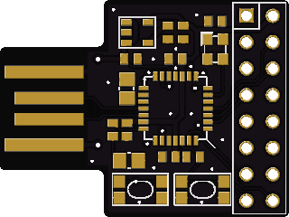
- maplehd.png (39.4 KiB) Viewed 469 times
Ray
Gonna finish up the last few things and then work on the pcb design.
~Straw
If someone needs the rubbish “arduino header” than go out an buy a nucleo board otherwise don’t waste space on a PCB for that
In earnest: I’ve spent too much time getting the “arduino headers” on the nucleo “arduino compatible” but at least, I was asking me a simple question: “Do I really need them?” Guess what my answer was…
~Straw
http://www.aliexpress.com/snapshot/6630792458.html
This allows the Nano to be replaceable and limits the wear & tear with constant inserting and removing the board which I have found is a big cause of the female header failure. For those who may not know, there is a great product called DeoxIT which can be sparingly used on the male pins to remove oxidation and contamination while providing a lubrication coat to make insertion into the female headers easier.
Ray
~Straw
~Straw
People who read about my conversation of the nucleo board know, why those a-style pins are a “red cloth” to me: On nucleo you only get out a poor compromise: There is no possibility – even with peripheral remapping tricks – to get a full a-style specification out of it (with I2c, SPI, PWM, USART and ADC on the “right” place (maybe you have better cards with a board from the sketch) and as strawberrymaker wrote, the non 5V tolerant pins you always have to care about (for example: a shield taking the +5V and gives it -however- back to an ADC pin…)). So in my – flippant way – this was meant by me as constructive.
Ray: I’ve spent to many hours for this project to give up this for a little disturbing conversation here.But maybe I should my activities a bit withdraw before getting to emotional (My family would support this grateful
https://www.olimex.com/Products/Duino/S … INO-STM32/
~Straw
Long female headers broken through the board ended on the other side as male headers. I used them heavily on my semi built projects: Just put on the prototype circuit board via female headers and using (or probing/measuring) the pins on the other side for further developing.
Unfortunately I didn’t found them on ebay/ali, the (cheap) ones I had ordered were much too thin on the male side, so be warned and buy them better on mouser,…

Long female headers broken through the board ended on the other side as male headers….
Madias is right that may cause overvoltage if someone uses the wrong shield. On the other hand this is a custom hand built board, if someone does not know the difference between 5V and 3.3V I highly doubt he will have the knowledge to assemble the board in the first place.
Every one, not matter how experienced, may make a mistake and apply overvoltage to a board, but that kind of accidents will happen no matter if you use arduino headers or not. To apply over voltage to this board you need to feed the shield with it’s own 5V or higher source, because if you power the shield from the main board like many shields do, then the shield will get 3.3V
The Arduino Due is not 5V tolerant in all the pins, and people still use it.
A second option is to not use Arduino spacing, but then we can make a custom daughter card that plugs to it and provide Arduino spacing for anyone that needs it, exactly the same way that board Ray linked plugs in the nano and provides a different set of connectors.
We have even put voltage translators in that board to provide full 5V compatibility with more digital pins, or voltage limiting diodes in the pins that are missing them per the specs.
For PSU id say the L7805 wouldnt be bad, because it got a high output current and a bigger max. Input voltage compared to the ams1117. But i need to read the complete datasheet of it. the d2pak package would be good but i need to take a look at the price of it.
I threw the idea away with the external peripherals connector, as i dont think its usefull when there is no hardware for it. And the battery Circuit too. May get that one on another board i’ll work on after that one.
But i will keep the sd card and the footprint for the eeprom. eeprom is handy for adapting the circuit into a finished product. But i will take a look at the flash chip options and connecting.
I dont know if adding SDIO support would make sense. Is there any support for it in the IDE (inform of libraries) or much peripherals? (i only know the little sd card dev board which name i cant remember)
Just asking: would anyone be interested in buying single pcbs, a kit with the parts or even completely finished boards? Kits would be a great option imo, because buying the parts in bulk keeps the cost for one board down.
I’ll finish the schematic tomorrow, as i got a long weekend ![]()
Just my thought, any critism is wished ^^
~Straw
If the ESP is still relevant we need also a really good 3.3V supply. Another problem with the ESP could be the indifferences, so good shielding would be necessary.
I would be interested in a kit or PCB. I just wonder if you have good connections to produce the whole board for low costs (I don’t think you gonna produce 1K and up
Are the SMD parts now 0805 sized?
Yeah parts are 0805. I dont think that there are more than 5 or 10 people interested in a complete manufactured board, so that wouldnt be that big of an deal to solder it by hand (or with solder paste and an oven). with the pins, i think i will go with female ones and not populated points for male ones.i think for the esp i will add a decoup cap. I will try to put the ports away from anything noisy like the psu.
~Straw
I’d be interested in a board (kit), though I’m not sure when I’ll have time to build it.
I’ve only soldered some DIL SMD IC’s and that was very messy, but my normal soldering is good, as I’ve been soldering since I was a kid.
PS.
Re: Power consumption on regulators
Is the 1117 a linear or “switching” regulator ?
I don’t think for this board it matters about power consumption, but I’m curious about other applications where low power may be useful, so having a regulator that is not constantly wasting loads of power would be of longer term interest to me.
Im still thinking about a STM32 Pro Mini (smaller than the maple mini) but not quite sure.
The problem (for me atleast) when searching for another regulator is that it should be available from ebay/aliexpress as sites like mouser or digikey charge way too much for shipping (20€). And “german” online electronic shops have a limited offer.
~Straw
I know what you mean about Mouser etc.
I used to buy from Farnell (Element 14) as they have a warehouse in Australia, but they changed their minimum order for free shipping, so that unless you are buying in bulk for a whole batch of boards, its they are too expensive to use.
BTW. Did you see the other thread about the STM32F4STAMP board ?
viewtopic.php?f=39&t=118&p=955&hilit=STM32F4STAMP#p955
It looks an interesting board, but I could not see if it was open source etc
About the STM32F4STAMP board, I don’t want to remove any credit to Frank Zhao who graciously gave me a PCB, but this board is quite light weight, there is nothing other than the CPU. But it gave me a great opportunity to introduce myself in the STM32 world, even before I purchased my first Maple Mini clone. I played with it using native STM libs, now I wish more : stm32duino !
About “Custom Communitydev board”, sure the STM32F4STAMP board can be an inspiration, but the NetDuino2 too since it is more arduino style with Ethernet on board. Here is the other thread : viewtopic.php?f=39&t=115.
@Straw ? please look at Netduino2Plus schematic and start dreaming about it …
The one I liked the most from what I found on mouser was AP2114H. I posted the link in the second page of this thread. It is cheap enough, only shipping charges may kill the deal if don’t need anything else from the same place.
It has super slow quiescent current, good capacity (I think it was 1 AMP or more), good input voltage range. Seems like a winner to me for anyone not liking the 1117, and as the size and pinout is the same, no need to design a different board just for that. So anyone can choose which one to install.
I remember there were more similar regulators in Mouser, some more expensive, some with a smaller amperage… I am sure something can be found for cheap in any part of the world that would be compatible with the 1117.
Still not quite sure if i should add arduino pins and break the other unused pins out or leave it the way it is.
~Straw
You might wish to consider using dirt cheap dirty pcbs http://dirtypcbs.com/about.php
This is an absolutely no-frills Chinese boardhouse that delivers boards at rock bottom prices.
http://dirtypcbs.com/about.php
Ideally make the prototype fit into 5x5cm or 10x10cm to get the best price. 10 off 5x5cmfor US$14 or 10x10cm for US$25
The usual term for this operation is “scallywags” – but they receive good feedback and offer a good basic service.
This weekend, I’m going to cook up a basic 5×5 board design using the 64 pin STM32F103.
regards
Ken
Current State of progress: (right click and open in new tab)

What changed:
-Analog LDO
– Different 5V regulator (AZ1117). Much wider range, but only 500mah.
-Jumper if the analog ldo isnt populated
-Finished the eeprom
Still need to decide which npn transistor i should use (currently MMBT3904 on the reset circuit and BC846A thought for voltage source selection and as a pwm driver)
Missing:
-Reverse Polarity Protection Diode
-Switching back to Micro USB
Im still not sure if i should use the arduino layout and then still pinout everything. If there isnt any new idea, i will start with the board soon ![]()
~Straw
You can also check this page to compare different vendors. You can select the size and the shipping time to sort them.
http://pcbshopper.com/
I would probably be interested in getting a couple of bare pcbs or pcb and components.
BTW my order of RGT at extremely cheap prices was cancelled cause the price was not correct.
can you attach the drawing as a PDF, its hard to read as an image
I’ve checked the boards settings and it should allow PDF’s
Thanks
Roger
Here it is:
PDF
~Straw

~Straw
On the eeprom, why there are jumpers for VCC and GND ?
There is also missing jumper for the A2, and the WP should not be left unconnected, it should be grounded.
On the MicroSD, there is usually a pin 9 for CardDetected which can be attached on an MCU GPIO as interrupt.
Some other pins of the MicroSD doesn’t seems to match the normal pinouts.
MicroSD carsd have only 8 pins. The CD pin is connected to cs. I will need to think again if micro sd or sd would be better. But i think there is a mistake in the schematic anyway, thanks for pointing that out ![]()
~Straw
New link (8.36 USD)
http://www.aliexpress.com/item/A96-Free … 4.2.MhxjOU
compared with the 2.4” you pay 2USD more for greater usability (with 2.8 you get a really chance to hit the right “button” on the touch panel)
I also have some of the 2.2” and they are also great (much more brilliant colors than the 2.8 touch one, but maybe the touch panel makes them cloudy) and with 4.88USD they are unbeatable (price)
@straw: Nice trick with the item number, but for most .com or .co.uk sellers Austria doesn’t exist: “Kein Versand nach Österreich” You know as “country neighbor” how impassable and dangerous the alps and/or the Austrian native inhabitants are ![]()
Guess i’ll replace it with that touchy one (or add compability). For me there isnt a prob. ordering from co.uk, as it still ships to Germany.
@madias
Thats a nice one, will def. replace it for the 2.4.
Will post a Picture to the (final) schematic today or tomorrow.
~Straw
I know this adds a whole level more complication to the board… But…
It looks like Rick has got the Black Magic Probe working using a separate C8 board as the probe, and the Eclipse dev team tell me a windows version of the debugger will be released at the end of June.
So.. In the not too distant future I can see a requirement for a board that has a F103C8 co processor that provides in circuit debugging.
Perhaps we should have a “Pro” version of the board that has the extra processor and another USB connector ?
If I wasn’t so busy, I’d offer to add it, once the layout was compete, but I doubt I’d have time ![]()
Anyway, its just a thought
@Roger
Like that idea. gonna take a look at rick’s project. Shouldnt be too hard in terms of circuitry and maybe i find some space on the bottom of the pcb. For the screen: How are SPI Connection handled over f.ex. SPI2? Elsewise i need to choose some more cs pins.
~Straw
They could be rewritten to use spi2, but I think you should set the LCD to just use spi1. We can always use spi2 for other things that are not onboard.
~Straw
So you can run multiple devices on the same SPI bus, but using separate GPIO lines for each CS line on external devices.
With SPI2 and SPI3 , I don’t think anyone came up with an ideal solution.
I think the best option is to duplicate and rename the SPI class to be SPI2 and have it configured to use the 2nd SPI channel (MOSI, CLK, MISO), but most libraries are hard coded to use “SPI”
So allow libs that are hard coded to use SPI, to use SPI2 is not going to be easy, especially as they are often instantiated globally, and in C we can’t govern the order in which the global vars or instantiations occur ![]()
Well, we get some control, but it would be a hack to try to move the SPI instantiation ahead of everything else
Schematic:

Currently replacing the old pinheaders with the pinheaders of the sparkfun library, like their footprint more. Also I need to work out the PWM Pins and BMP needs also to be done, just added the footprint. I will also change the multiple pinout of SPI2+ and I2C/I2S2+ to max. of 2 and the SPI1/I2C1/I2S1 to 3 or 4.
Now JTDO is connected to the STlink, as described in the datasheet of the nucleo board. atm its marked as reserved, guess something will come. and JTAG header is there
The I2C1 Direct port is thought for connecting sensors or other i2c boards directly, as most of them have the same pinout (3v3, gnd, scl, sda or vise-versa). tested it on the i2c oled, mpu-6050 (acc+gyr) and magnetometer.
EEPROM: Well i think i’ll leave it there, but i cant make sure its working, as i dont have it here and i cant port libs (but may this will change). Guess i’ll leave the footprint but wont add it for the BOM.
The esp8266 will get a bigger cap and i will pinout all the other pins.
To the screen: I didnt connected the sd card slot as there is going to be one onboard with more functions (Card detect). Could also connect it to the same ports of the oboard sd card. The Backlight is driven by a npn transistor (BC846). Guess 100mah should be enough as i wouldnt think them having more than 4 leds in them.
Should work the schematic out today ^^ Then i will also post the BOM with minimum config and maximum.
~Straw

Changelog:
-removed SWD from onboard
-removed ch340 from onboard
-added Black Magic Probe Schematic
I will take one more look to make sure everything is fine and create the Bill of Material aswell as the options.
~Straw
EDIT:
PDF Version
Eagle Schematic
http://puu.sh/hXSBz/297e3d2b82.xlsx
Will search the items in bulk for 10pcs and post the price later one for one set ![]()
~Straw
Now that the generic bootloader seems to be working quite well, there may not be a need for the full reset circuit, but instead it just uses a 1.5k from USB D- to Vcc
However its not had extensive testing, so perhaps we can just bridge the pads for one of the USB reset transistors if they are not needed, as I guess for safety we should retain the possibility of using the full reset circuit
To the Price: The Price is going to be ~16€ for the Set.
(Yeah I added 4€ to the price, guess after the time i spent on this project its not that bad).
And after its finished i’ll post it completely on Github ^^
~Straw
~Straw
@Roger
So like the BMP is re-enumerating?
It has a 1K5 Resistor from PA8 going to D+ to drive it high. Would make it less complex then. Would be nice to hear if its working without problem ^^.
~Straw
EDIT: Is the Pin still PC12 (like on maple) ?
Re re: bmp Re enumeration
From what I understand Rick modified the Bmp firmware so it just needs 1.5 k pull up on PA12 ( USB D-)
However Rick seems to have damaged at least 2 of his boards, which he thinks could be changes to the core code to get USB serial to re enumerate, but Im wondering if it could also be because of testing his boards as a BMP
But we did some testing yesterday to see if using GPIO to drive D- High and Low and I can’t see how this could have damaged the chip
Couldnt we use the normal firmware? As its basically just a BMP in terms of circuitry.
Different story for the RET6
~Straw
Using the official BMP circuit is probably the best approach as its guarantee to work, i.e we need to include the reset hardware rather than relying on togginging PA12 in the code.
However, one note… According to Rick, there are multiple versions of BMP kicking around. including some derivatives which are probably better than the original
e.g. I noticed one called the “Cricket probe”
But i will search for other
~Straw
However Rick seems to have damaged at least 2 of his boards, which he thinks could be changes to the core code to get USB serial to re enumerate, but Im wondering if it could also be because of testing his boards as a BMP
Victors code, seems to drive PA12 to LOW and then sets it back to INPUT FLOATING.
Perhaps using pull up / pull down mode on that pin damages it. I hope not as thats what victor is now testing (from what I understand from his posting)

Will work on the Board Layout now. will post a update on that one as soon as i managed the component layout out.
~Straw

Thats going to be the Black Magic Probe part. But need to take a look if the Ground Plane is OK. Maybe the “Heatsink” of the AMS is getting bigger and combined with the Top layer (with vias).
~Straw
EDIT: these are 0.1mm, so its 4cmx3.7cm
BTW. What are you using to do the design, KiCad or Eagle or something else ?
Eagle
~Straw
I will set up a github page and post here the updates.
~Straw
When you have some spare time, can you put a PDF of the schematic in github, as its easier than using Eagle (and some people who would be interested may not have Eagle)
Well, currently I swapped out the resonator with a smd crystal, easier for routing things.
Also the current Board Design is an Idea for it, but i think i wont stick with it either.
@mrburnette
The Price is ~ 12€ (with pcb and headers) if you buy everything yourself.
In terms of a kit, I think it will just contain the smd parts and the pcb and the mcu’s and the header should be bought by the one who wants it. But that maybe changes.
~Straw
In terms of a kit, I think it will just contain the smd parts and the pcb and the mcu’s and the header should be bought by the one who wants it. But that maybe changes.
About $13.50 USD today …
if you buy everything yourself.
Ummmm…
I’m using Teensy3.1 as a yardstick to measure this initiative and they are $19.80 – up a bit since Adafruit started to sell them! Bad, bad Limor.
Maybe I’ll strap 4 Maple Mini togethers and implement Symmetric MultiProcessing ![]()
This is the issue I always run into when I design a custom board … unless it is something that simply does not exist, the BOM always exceeds the clone, mass-produced generic stuff… yes, I have to hack the hell out of generic stuff sometimes and that does waste time.
Anyone in the forum constructed a reflow oven yet? The only way this makes economic sense (to me) is a group-buy of parts: the one uC, etc. is going to be rather costly but the end product is appealing. You’ve done a great job Straw…
but, I’m probably going to just play with Maple Mini’s as I never really do anything much that taxes a 328!
Ray
The only way I could imagine getting them cheap is to get the board design(s) to the chinese manufacturer. But my guess would be that the community isnt that big that they could see a potential in it. yes, we are big, but compared to Leaflabs or (as you mentioned) PJRC, stm32duino is not really reliable for the manufacturers to make the board in a big run (> 200).
Like the idea for producing them Forum-intern, but that would still add up to the cost, so selling them as a “kit” with everything you need to have and an Instruction how to solder it would be a cheaper possibility. (depending on manufacturing possibilities, how many boards etc. But i dont think anyone got a pick-n-place and an industrial reflow oven in the garage ![]() )
)
One more thought of my own. I think we’re missing something like a Pro Mini for STM32. I personally like them to use in small spaces or wearables. Stuffing a complete Maple mini into a wristwatch doesnt look good in the end. C8T6 is using nearly the same space as the QFP ATMEGA328.
Sidenote: Whats about updating the Wiki, or making a wiki on here?
~Straw
<…>
One more thought of my own. I think we’re missing something like a Pro Mini for STM32. I personally like them to use in small spaces or wearables.
~Straw
~Straw
~Straw
http://chipkit.net/forum/viewtopic.php?f=17&t=3132
Ok, it’s a PIC32 but nice USB connector!
I have a box of PSoC prototyping board, a mix of 4100s and 4200s, and that is the circuit board USB connector they use! It looks nice, but it actually sucks. I eventually found a short USB extension cable, bent the female connectors in the cheap cable so they would compress against the PC substrate better. Dangling ’em in the PC simply causes Windows to enumerate at the worst times due to poor connections.
Ray
I also suspect these small dongle type devices are a bit of a gimmic. I have some little AVR based USB dongle boards, but I have not really found a use for them.
I think USB dongle devices really need to be self contain and not also have a bundle of wire hanging out of them, as even if it has a proper plug , you could easily stress the socket and PCB in you PC or laptop.
But I can see how pairing something like. NRF24L01 with a dongle board could be useful, or perhaps a 433mhz transmitter or receiver, or perhaps a micro SD card to form a special type of storage
~Straw
like madias says, 50×50 mm or 100×100 mm is price friendly for manufacturing on some PCB fa, ie, dirtypcbs or pcbway.
Dimension is going to be 100x100mm. 50x50mm wont be able, as the Black Magic Probe Part would take up the half of the place
Back to the topic:
Currently working out the final board design. Bottom left is the Black Magic Probe, next to it is the main mcu (ret6) and the rest of it is going to be pinout (with desciption), sd, usb, power connector, reset circuit etc.
It will be under 10x10cm.
Just noticed that the NPN Transistor IC is a little bit too small:

Lets hope that i made a mistake while making the footprint ![]() Cant imagine the IC being as small as a 0805 resistor.
Cant imagine the IC being as small as a 0805 resistor.
Well, just small things.
~Straw
~Straw
~Straw
However I’m not sure if driving the D+ line via GPIO may not really adhere to the USB spec. However as this board is only for hobby use, perhaps we can remove the USB reset circuit, and save some space etc
However I’m not sure if driving the D+ line via GPIO may not really adhere to the USB spec. However as this board is only for hobby use, perhaps we can remove the USB reset circuit, and save some space etc
The DISC line is not used in the new bootloader
Tried the bootloader out today, and it works really like a charm! Great job with the bootloader!
~Straw
No worries…
PS.
Victor_pv did a lot of the work on the new bootloader (getting the USB to re-enumerate), but I have also made loads of changes and enhancements to the code ![]()
Worked today again on it, deleted the old board files so i can begin (again) from scratch.started with the part placement of the mcu’s and began with the silkscreening of the pinouts to see how big they are going to end and then i could plan better in the end. And then it crashed.
Atleast i learned to actually press Strg+S while working, actually saves lives
Well….guess I need to start again. the 5th time.
Just looked the price for the ret6 again. ~15€for 10pcs + shipping, or 3,6€ for one mcu. seems quite good. and the store even offers a huuge amount of stm32 ics.
[url = http://de.aliexpress.com/store/1079241]Link (store) [/url]
~Straw
If you need to keep a version history, Git is a fairly good way of doing this.
You don’t need to push the repo out to the cloud, you can just run a local copy.
I just downloaded GitHub’s tools, and use the git shell (I’m not sure if the GUI version is any good)
You can get free private repo’s on bitbucket.org, or if you want to make the board design public, you can always use GitHub as its free for open source.
I now use git for quite a lot of my projects, as its very handy to be able to go back to old versions !
