I need to invert the logical level of an input digital signal with the blue pill (I want to avoid using external hardware for that).
The only restriction is that the output signal should not be delayed by more than up to 200 ns compared to the input.
This restriction already excludes the inverting within an ISR of attachInterrupt() which I tried and which takes ~1 µs.
Any other ideas?
Anyone already did something like this and has experience and/or sample code?
I think It should be doable with a timer but I thought I better ask before I start to do some trials.
http://www.learningaboutelectronics.com … ircuit.php
Doing it quickly in software however without using an ISR .. hmmm let me think about that.
You could try overriding the IRQ handler with:
extern "C" void <__irq_handler_name>(void) {

//optimized code here

}
I wonder if somehow you can use a timer for this, and use the OnePulse system, using an external trigger ?
I will try to hack one of the __irq_extix ISRs in libmaple, and check the delay in that case.
Otherwise I have to analyze a possibility using a timer.
- Keep systick available
- Ability to use the main loop for other stuff
I want to keep systick.
And I want to keep USB serial.
And I think it won’t be less with any IRQ.
So I see myself forced to study the possibilities offered by timers.
Anyway keep us posted on your progress, I’m curious!
Set a timer for external input. I believe the timer can be set to count on both edges (but this where I may be wrong, if only counts in one edge, you get a /2)
Set overflow to 1.
Set channel N to flip flop on each compare match, and set the compare to 1.
Every time the input signal changes level will increase the count to the counter register, will match the compare register, and the channel will flip level.
Now, all this said, I would go for a hardware solution as Andy suggested.
At each input clock an IRQ is generated, where I want to change the input polarity to get a new IRQ at changed polarity.
Now the problem is that the timer keeps counting till overflow, despite I stop the timer and reset the counter.
Hm.
If instead you want to keep on with a sw solution and have no luck with timer, I’d suggest to try this:
- bind your input to 2 pins using different EXTI IRQs (i.e. PB2 and PB3)
- define your output pin (i.e. PB4)
- configure 2 different EXTIs for rising vs falling
Not sure this code is completely correct because I couldn’t test it anyway it can be a tip..
uint _delay=2000;

//gpio_reg_map *gpiob_regs;

register __IO uint32 *gpiob_bsrr asm ("r8");
void setup() {
// put your setup code here, to run once:
Serial.begin(115200);
pinMode(LED_BUILTIN,OUTPUT);
pinMode(PB2,INPUT);
pinMode(PB3,INPUT);
pinMode(PB4,OUTPUT);
//gpiob_regs=GPIOB->regs;
gpiob_bsrr=&(GPIOB->regs->BSRR);
//enable EXTI2 as RISING on PB2
bb_peri_set_bit(&EXTI_BASE->RTSR, 2, 1); // rising
exti_select(EXTI2, EXTI_PB);
bb_peri_set_bit(&EXTI_BASE->IMR, 2, 1);
nvic_irq_set_priority(NVIC_EXTI2, 0xE);
//enable EXTI3 as FALLING on PB3
bb_peri_set_bit(&EXTI_BASE->FTSR, 3, 1); // falling
exti_select(EXTI3, EXTI_PB);
bb_peri_set_bit(&EXTI_BASE->IMR, 3, 1);
nvic_irq_set_priority(NVIC_EXTI3, 0xE);
nvic_irq_enable(NVIC_EXTI2);
nvic_irq_enable(NVIC_EXTI3);
}
void loop() {
// put your main code here, to run repeatedly:
Serial.println("It's working");
delay(_delay);
}
extern "C" void __irq_exti2(void) {
//gpiob_regs->BSRR=0x10;
*gpiob_bsrr=0x100000;
}
extern "C" void __irq_exti3(void) {
//gpiob_regs->BSRR=0x100000;
*gpiob_bsrr=0x10;
}
No additional external hw is one of the requirements.
The timer solution should work, just that i have to spend some more time with it ��
Luckily there are couple of micros between the input signal edges so that after generating the inverted signal there is time for an isr.
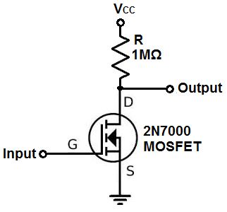
a. better use a logic level mosfet, with Vgt=1.0-1.5V
b. always ground the gate with something like 10k (or less)..
//-----------------------------------------------------------------------------

//  Example of Timer external clock mode 1.

//  At each input edge the output changes its level (signal inverter)

//

//  This example uses:

//  - Timer2 channel 1 as external clock input

//  - Timer2 channel 2 to generate the pulses.

//-----------------------------------------------------------------------------

void timer2_isr(void)

{

//*outPort = outMaskHi;  // set LED pin

timer_set_count(TIMER2, 0);

//Timer2.setPolarity(TIMER_CH1, 1^Timer2.getPolarity(TIMER_CH1)); // change input signal polarity

timer_cc_set_pol(TIMER2, TIMER_CH1, 1^timer_cc_get_pol(TIMER2, TIMER_CH1)); // change input signal polarity

//*outPort = outMaskLo; // clear LED pin

}

//-----------------------------------------------------------------------------

void Timer_setup()

{

// setup PA1 (Timer2 channel 2) to PWM (one pulse mode)

pinMode(PA1, PWM);

// setup PA0 (Timer2 channel 1) as input

pinMode(PA0, INPUT);
// stop the timers before configuring them

Timer2.pause();

Timer2.setPrescaleFactor(1); // 0.125 µs resolution

// this is new:

timer_set_cc_mode(TIMER2, TIMER_CH2, TIMER_OC_MODE_TOGGLE, 0); // Timer2.setMode(TIMER_CH2, TIMER_OUTPUT_COMPARE);

// detect first count

Timer2.setCompare(TIMER_CH2, 1);

// counter setup in slave trigger mode counting on external TI1 edges

Timer2.setSlaveFlags( TIMER_SMCR_TS_TI1FP1 | TIMER_SMCR_SMS_EXTERNAL );

// attach interrupt

Timer2.attachInterrupt(TIMER_CH2, timer2_isr);

// start timer 2

Timer2.refresh();

Timer2.resume(); // let timer 2 run

}


