I have just make small code fix to get it compile on atollic studio, but at first I was getting message that I have to little RAM, but on original project CPU has same amount of ram as bluepill 20K…
So I have just tried to put smaller screen size, but then it hangs while clearing screen in simple loop.
If someone want to tryout to debug here is code for atollic…
Edited:
Fixed problem with fb array that I made by copy pasting …
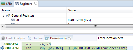
- instructionFailes.png (10.76 KiB) Viewed 568 times
fb was defined two times and that is why code was to big.
and I made mistake while copy pasting from mbed and defined fb as single dimensional array, and it needs to be two dimensional (that was crashing code)…
I will test it after on VGA and put code on git if all is working…
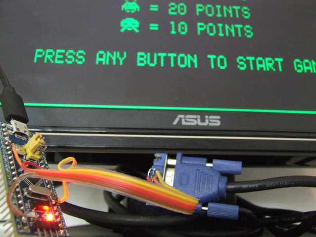
- space2.jpg (35.42 KiB) Viewed 539 times
So much fun stuff is going on at the moment.
Thanks Goran…
Most probably there is real 75ohm (the 75ohm resistor) at the RGB inputs wired against Gnd.
More hints here.
https://en.wikipedia.org/wiki/Video_Graphics_Array
If you want shades of grey in your VGA (or shades of green in this case), then you would need to use multiple pins and a voltage ladder, and keep the total voltage of the signal levels within the correct range.
In summary, since we are only doing 1 bit per pixel video, then on/off is all we need, however the video signal is not actually within spec. rather it is probably within safe limits in most cases.
You could put a 100K pot between the VGA output pin and ground, and take the wiper pin to the monitor to give you a brightness control. Uses screened cable, and be aware you may introduce reflections/ghosting in the image if the cable is unscreened, or too long. You could also feed the signal to the red and green pins via other similar pots to allow you to choose pretty much any other single colour you like..
stephen
Thus a 470ohm resistor at the MCU output will create a voltage divider 470 / 75ohm = 0.137. That gives you max 0.7V at 5V.
A 270ohm / 75 ohm gives you 0.217 * 3.3V = 0.71 max at 3.3V.
With STM32 you must use 270ohm resistor from mcu pin to VGA connector at R/G/B inputs.
@ahull: a 100k potentiometer will not work.
So a 470ohm resistor at the MCU output will create a voltage divider 470 / 75ohm = 0.137. That gives you 0.7V at 5V.
A 270ohm / 75 ohm gives you 0.217 * 3.3V = 0.71 max at 3.3V.
So a 470ohm resistor at the MCU output will create a voltage divider 470 / 75ohm = 0.137. That gives you 0.7V at 5V.
A 270ohm / 75 ohm gives you 0.217 * 3.3V = 0.71 max at 3.3V.
That is the right approach
If the stm32 connected directly the pin’s output current would be 3.3V/75ohm = 44mA at least, that is off the spec, sure.
Have an ancient Acorn Atom schematic instead. This is how the original 6845/6847 based video boards pushed out the pixels..

We are spoiled by all these $3 LCDs. ![]()
seems it allows variation of the white intensity
srp
http://quinndunki.com/blondihacks/?p=955
Or we could be really authentic and just use rainbow coloured cellophane ![]()
BTW the 6847 datasheet does go in to some detail about the circuitry of the luminance ladder and a great deal of detail about the timing and so forth needed to produce its analog colour component signals.
.. another reason I mentioned the 6847 and posted the Atom schematic is that the Acorn Atom (as a self assembly kit) was the first computer I actually owned (as distinct from the many I had played with up till that point), so I have a bit of a soft spot for it, and am pretty familiar with its quirks and design. It was by no means the most quirky design around, there were many others. https://en.wikipedia.org/wiki/List_of_h … o_hardware
https://hackaday.io/project/9383-pacman … 41-and-vga
Looking at the files, it does so using several pins for each code with different divider resistor values:
https://github.com/DrNCXCortex/Pacman-A … master.ino
https://hackaday.io/project/9383-pacman … 41-and-vga
Looking at the files, it does so using several pins for each code with different divider resistor values:
https://github.com/DrNCXCortex/Pacman-A … master.ino
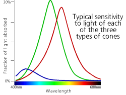
but I found others that look different where blue sensitivity is not so bad

So… RGB 332 would be the best way to pack colour in 8 bits. (I think the video systems I worked on, years ago, were possibly 16 bit colour as I don’t think the numbers of bits were 322, more like 664)
http://lslwww.epfl.ch/pages/teaching/co … es/VGA.pdf
-A VGA video signal contains 5 active signals:
• horizontal sync: digital signal, used for synchronisation of the video
• vertical sync: digital signal, used for synchronisation of the video
• red (R): analog signal (0-0.7 v), used to control the color
• green (G): analog signal (0-0.7 v), used to control the color
• blue (B): analog signal (0-0.7 v), used to control the color
blue pill / maple mini do not have a DAC, but those STM32F407VE/ZE series have them, just that i’m not too sure if the built-in DAC is fast enough to generate all the RGB signals to do full color vga rendering
in addition a full color rendering 640x480x24 bits(3 bytes) would take a whopping 921k of screen buffer memory– The video signal must redraw the entire screen 60 times per second to provide for motion in the image and to reduce flicker: this period is called the refresh rate. Refresh rates higher than 60 Hz are used in PC monitors
– In 640 by 480-pixel mode, with a 60 Hz refresh rate, this is approximately 40 ns per pixel. A 25 MHz clock has a period of 40 ns
F407VE/ZE it seemed has only 2 channels for DAC outputs, i’m not too sure if that could be multiplexed
it would seem 40ns may be pretty difficult to do on stm’s f4 dac as well
perhaps pair up stm32f1 or better f4 with a hi speed parallel dac and additional ram? but the specs seem to say that video circuits tend to be specialised and dedicated rather than use generic mcu parts e.g. dac, dma etc. or perhaps pair up multiple stm32f1 to do it, but dac would still be a problem to get 640x480x24 bits color x 60 hz
even with 1 bit of each color R, G, B, my thoughts are that that would give 8 different color combinations that way
I think you missunderstood.
This thread is not about replicating a complete VGA display system, its just that a Blue Pill can be turned into a 8 colour Space Invaders game, outputting straight to a VGA monitor..
Quite an achievement for a general purpose $2 board.
at 3 bits per pixel, 640x480x3/8 ~ 115,200 bytes for the screen buffer
my thoughts are that this seem ‘easier’ on an f407 chip with a good amount of sram. i’m not too sure if ccm ram which do not do dma could be used for that
the other way is to compute each pixel and draw it directly without the screen buffer ram, my guess is it may be somewhat ‘more difficult’
these days with lcd monitors, i’m not too sure if we’d need to run refresh at 60hz, in the sense that the lcd monitor would possibly ‘remember’ that dot we draw on the display after all. hence all that ‘refresh’ is after all ’emulated’, we can then run at much lower pixel rates (less than 25mhz) without compromising display quality
this may be a ‘big deal’ in a sense if stm32 could simply output on vga (lcd) monitors, no need for ili9341 and all those etc
the crt types could still be tough to do due to the 25mhz pixel rates at 60hz refresh
I think you missunderstood.
This thread is not about replicating a complete VGA display system, its just that a Blue Pill can be turned into a 8 colour Space Invaders game, outputting straight to a VGA monitor..
Quite an achievement for a general purpose $2 board.
Probably it could be done with an Atmega:
http://www.theresistornetwork.com/2013/ … ation.html
![]()
I recall these old systems used to do tricks like do the game code computation during the horizontal and vertical frame flyback periods. I forget how long each of these are, as its a bit before my time
But I really appreciate how hard the designers used to have to work to get every last ounce of processing power out of what are now seen as exceedingly show processors, with very limited RAM, and not that much ROM.
f4 should most likely be able to ‘do it alone’ & would likely be able to manage 640×480 resolutions. i think on f4 APB2 can run at 84 mhz and APB1 runs at 42mhz it would likely be able to handle the 25mhz pixel rates, just that i’m not sure if say we bit bang at 21mhz (42/2) if that may cause any issues with the video timings etc
… and yes.. it could play space invaders … in a rather blocky, monochrome, snowy, jumpy manner…
You need 80kB video buffer, which fits inside F407.
You get maybe 50us to shoot out 400pixels or bytes. That is 125ns per pixel. That is an 8MHz byte stream off the gpio.
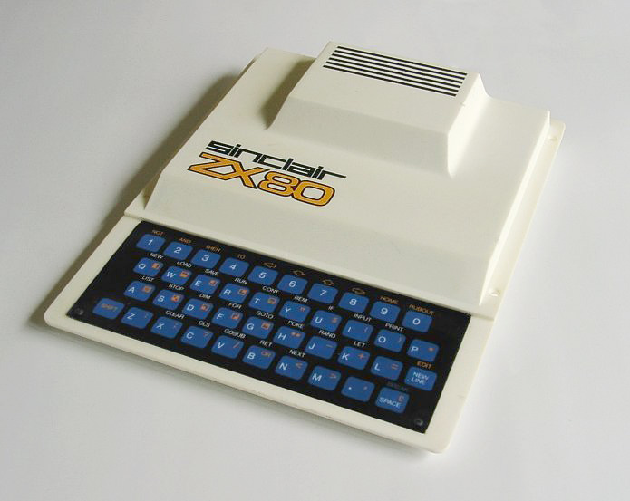
ZX80/81: The ZX81 did not use pixels resolution, but 8×8 fixed chunks generated off ROM char gen, afik (I owned one..).
Basic setup got 1kB of ram, inclusive video
I think that even when typing in the code, that the screen could blink ( but I may be wrong on that front)
I had one when I was at highschool.
The ZX81 was better, as it could maintain video output and run code, but I dont recall what the difference was. Presumably the Zx81 had some sort of dedicated video output dma system.
As a result, the TV picture was at the mercy of various other systems, if you loaded from tape, you got snow. If you didn’t stick to very strict timings in the code, snow.. etc.
The most important parts in ZX80/81/Spectrum – the R4-R11 resistors in the data bus
You need 80kB video buffer, which fits inside F407.
You get maybe 50us to shoot out 400pixels or bytes. That is 125ns per pixel. That is an 8MHz byte stream off the gpio.
ZX80/81: The ZX81 did not use pixels resolution, but 8×8 fixed chunks generated off ROM char gen, afik (I owned one..).
Basic setup got 1kB of ram, inclusive video