#include <RTClock.h>

//this is where we will store the unix time

uint32_t tt = 0;

//these will store your hours, minutes, seconds for display

//we will update these variables whenever we read the RTC so we can use them over and over wherever we need

byte currentHours = 0;

byte currentMinutes = 0;

byte currentSeconds = 0;
// initialise the RTC library.
// NOTE: 'RTCSEL_LSE' assumes you have a 32.768Mhz crystal setup physically attached to the appropriate pins
// on the microcontroller. Pins PC15 and PC14 are the RTC crystal pins.
RTClock rtc (RTCSEL_LSE);
void setup() {
Serial.begin(9600);
//you can also SET the rtc time with rtc.setTime(unixTimestamp) where unixTimestamp is a unix timestamp
}
void loop() {
//get the RTC time (returns unix time, a 32bit integer representing seconds elapsed from Jan 01, 1970)
tt = rtc.getTime();
breakTime(tt);
if(currentHours < 10) { Serial.print(0); } //leading zeroes to look nice
Serial.print( currentHours );
Serial.print( ":" );
if(currentMinutes < 10) { Serial.print(0); } //leading zeroes to look nice
Serial.print( currentMinutes );
Serial.print(":");
if(currentSeconds < 10) { Serial.print(0); } //leading zeroes to look nice
Serial.println( currentSeconds );
delay(1000);//or whatever
}
//stolen and simplified from the time library by Paul Stoffregen
//just derives the hours, minutes, seconds from the unix timestamp and sets the global variables we use for display to those values
void breakTime(uint32_t timeInput){
currentSeconds = timeInput % 60;
timeInput /= 60; // now it is minutes
currentMinutes = timeInput % 60;
timeInput /= 60; // now it is hours
currentHours = timeInput % 24;
}
It does
Btw errata recommends for the LSE external oscillator:
It is recommended to mount an additional parallel feedback resistor (from 16 MΩ to 22 MΩ) on board to help the oscillation start-up in all cases (see Figure 1). For more details on compatible crystals and hardware techniques on PCB, refer to AN2867 application note.
Also, the datasheet for the STM32F103x8 says there is a 5M feedback resistor built into the chip itself (pg. 54), so that’s why I said it’s optional.
I have DS1302, DS1307 and DS3231, hopefully one of those fit into this build.
Kurt
Slightly off topic, but if you want a smart watch, it may be easier to re-purpose an nRF51822 based smart watch / fitness tracker.
You can get them for less than $20, with an nRF51822 with 256k flash and 32k ram, 64 x 32 pixel OLD display, 3 axis accelerometer, 1 button, 1 vibration motor and also a heart rate sensor
I have one on my bench at the moment that I’m getting to grips with
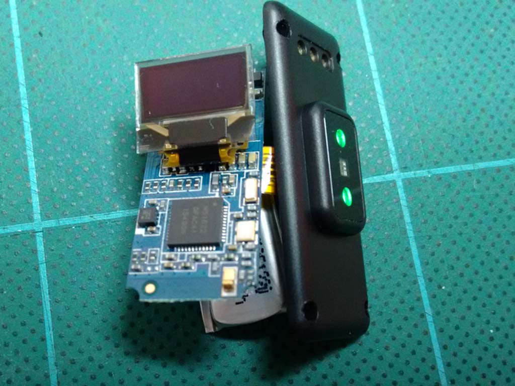
- ID100HR_front_smart_watch1.jpg (112.52 KiB) Viewed 3475 times
Btw errata recommends for the LSE external oscillator:
It is recommended to mount an additional parallel feedback resistor (from 16 MΩ to 22 MΩ) on board to help the oscillation start-up in all cases (see Figure 1). For more details on compatible crystals and hardware techniques on PCB, refer to AN2867 application note.
I have DS1302, DS1307 and DS3231, hopefully one of those fit into this build.
Kurt
The mid current is with DS1307, needs resonator and capacitor, the precision same as w/ the PCF.
The highest current is with the DS3231 – 1.5uA. It does not require external components, it is temp compensated and possess aging tuning, and precision is a second per month (mine did 2secs/6Months, at room temp, after messing with aging tuning).
The RTCs inside MCUs are sometimes even more power hungry, need an resonator and capacitors, have sometimes a simple tuning via manipulating the seconds register. Precision similar to DS1307..
PS: my ETA2824-2-elabore inside my watch does -9sec/day and I am happy.. ![]()
I saw you posted that eBay link on some other thread. But which exact model is it? I’d love to get one and play around, but the link you posted had various products at various prices, been meaning to ask which one it was.
Regarding my smart-watch, I have the schematic done and the core of it is working on my breadboard. I want to make a custom PCB and all that jazz, not because it’s easy but because it’s hard ![]() ) I’ll post a thread in the projects section when it looks a bit more interesting. The plan is to have a watch with a gpio female header on one side that you can poke stuff into and an oscilloscope.
) I’ll post a thread in the projects section when it looks a bit more interesting. The plan is to have a watch with a gpio female header on one side that you can poke stuff into and an oscilloscope.
I recommend the ID107HR as it has touch button on the front as well as a real button on the side. I paid around $18 USD including postage, (on AliExpress)
Just make sure the description includes nRF51822 as a lot of these are miss-sold.
I have everything working on it except the heart rate detection

