Here is the TEK 4010/14 you may get at ebay most probably..
https://www.youtube.com/watch?v=IztxeoHhoyM
Have a look at the beautiful way those old vector graphics terminals worked.. ![]()
https://en.wikipedia.org/wiki/Tektronix_4010
To try with vector based graphics at home, and today, you may try the simple Demo below – all you need is a BluePill or something like that and TeraTerm terminal, or something like that.. ![]()
UPDATE: added printing out the elapsed time, added GIN, added Sprites, added defines for colors, line styles and font sizes
// A simple TEK4010/4014 Graphics Vector terminal - DEMO

// You need ie. TeraTerm or Xterm switched into TEK4010/14 Emulation

// The current vector's addressing is 1024x1024 (10bit)

//

// Loosely inspired by

// http://www.ne.jp/asahi/shared/o-family/ElecRoom/AVRMCOM/TEK4010/TEK4010gdisp.html

// and other related information found on the web

//

// Provided as-is, no warranties of any kind are provided :)

// by Pito 7/2017
#include "Arduino.h"
void setup() {
delay(3000); // Wait for USB
Serial.begin(115200);
}
void loop() {
// Draw some primitives on the screen for fun
// Origin (0,0) is the left bottom corner, y| __x
uint32_t elapsed = micros();
Tekcls();
Tekcolor(2);
Tekgraph(4);
Tekpoint(100, 100);
Tekpoint(200, 100);
Tekpoint(200, 200);
Tekpoint(100, 200);
Tekcolor(3);
for (uint32_t i = 300; i < 500; i = i + 10) {
Tekline(i, 400, i, 600);
}
Tekstyle(0);
Tekline(300, 300, 500, 500);
Tekstyle(1);
Tekline(600, 400, 200, 300);
Tekstyleb(2);
Tekcolor(7);
Tekplot(10, 700);
Tekplot(500, 30);
Tekstyle(3);
Tekline(400, 600, 100, 800);
Tekcolor(4);
Tekstyleb(4);
Tekplot(300, 330);
Tekalpha();
Tekfont(1);
Teklocate(700, 400);
Tekcolor(6);
Serial.println("Hello World !!");
Tekfont(2);
Tekcolor(1);
Teklocate(700, 300);
Serial.println("STM32duino !!");
Tekfont(0);
Tekcolor(2);
Teklocate(500, 200);
Serial.println("THIS IS A TEST OF TEK4014 !!");
Tekcolor(1);
Tekstyle(0);
Tekbox(300, 200, 600, 600);
Tekcolor(2);
Tekstyle(0);
Tekdot(150, 150);
uint32_t i;
for (i = 0; i < 360; i++) {
float q = i;
q = 3.141592f * q / 180.0f;
float r = cosf(q);
q = sinf(q);
q = q * 120.0f;
q = q + 195.0f;
r = r * 120.0f;
r = r + 580.0f;
Tekdot((uint16_t) r, (uint16_t) q);
}
Tekcolor(5);
for (i = 0; i < 360; i++) {
float q = i;
q = 3.141592f * q / 180.0f;
q = sinf(q);
q = q * 150.0f;
q = q + 195.0f;
float r = i + 30.0f;
Tekdot((uint16_t) r, (uint16_t) q);
}
uint32_t a = 450;
for (i = 1; i < 34; i++) {
Tekline(0, 450, 1000, a);
a = a + 10;
}
Tekalpha();
Teklocate(400, 100);
elapsed = micros() - elapsed;
Serial.print("Elapsed: ");
Serial.print(elapsed);
Serial.println(" micros");
delay(5000);
}
// ********************************************************
// TEK4010/4014 basic 10bit commands library
// For details consult the TEK4010/4014 manual
// Pito 7/2017 for stm32duino
// ********************************************************
// Colors for print, plot, dot
#define black 0
#define red 1
#define green 2
#define yellow 3
#define blue 4
#define magenta 5
#define cyan 6
#define white 7
// Line styles
#define solid 0
#define dotted 1
#define dash_dotted 2
#define short_dashed 3
#define long_dashed 4
// Font sizes
#define large 0
#define normal 1
#define small 2
#define smallest 3
// Clear Tek screen
void Tekcls() {
Serial.write(0x1B);
Serial.write(0x0c);
//Serial.write(0x0d);Serial.write(0x0a);
}
// Select a color (0-7)
void Tekcolor(uint8_t color) {
Serial.write(0x1B);
Serial.write(0x5b);
Serial.write(0x33);
Serial.write(0x30 + color);
Serial.write(0x6d);
}
// Switch to graphical mode with a line style (0-4)
void Tekgraph(uint8_t style) {
Serial.write(0x1D);
Serial.write(0x1B);
Serial.write(style | 0x60);
}
// Select a font size (0-3) for printing alphanumeric strings
// The actual font type has to be set in the Emulator
void Tekfont(uint8_t fontsize) {
Serial.write(0x1B);
Serial.write(0x38 + fontsize);
}
// Normal style lines (0-4)
void Tekstyle(uint8_t style) {
Serial.write(0x1B);
Serial.write(0x60 + style);
}
// Bold style lines (??)
void Tekstyleb(uint8_t style) {
Serial.write(0x1B);
Serial.write(0x68 + style);
}
// Switch to alphanumeric mode
void Tekalpha() {
Serial.write(0x1f);
}
// Draw a point as a small cross (??)
void Tekpoint(uint16_t x, uint16_t y) {
Serial.write(0x1C); // FS
Serial.write(0x20 + ((y >> 5) & 0x1F));
Serial.write(0x60 + ((y) & 0x1F));
Serial.write(0x20 + ((x >> 5) & 0x1F));
Serial.write(0x40 + ((x) & 0x1F));
}
// Draw a single dot
void Tekdot(uint16_t x, uint16_t y) {
Serial.write(0x1D); // GS
Serial.write(0x20 + ((y >> 5) & 0x1F));
Serial.write(0x60 + ((y) & 0x1F));
Serial.write(0x20 + ((x >> 5) & 0x1F));
Serial.write(0x40 + ((x) & 0x1F));
Serial.write(0x40 + ((x) & 0x1F));
}
// Draw a line from (x1, y1) to (x2, y2)
void Tekline(uint16_t x1, uint16_t y1, uint16_t x2, uint16_t y2) {
Serial.write(0x1D); // GS
Serial.write(0x20 + ((y1 >> 5) & 0x1F));
Serial.write(0x60 + ((y1) & 0x1F));
Serial.write(0x20 + ((x1 >> 5) & 0x1F));
Serial.write(0x40 + ((x1) & 0x1F));
Serial.write(0x20 + ((y2 >> 5) & 0x1F));
Serial.write(0x60 + ((y2) & 0x1F));
Serial.write(0x20 + ((x2 >> 5) & 0x1F));
Serial.write(0x40 + ((x2) & 0x1F));
}
// Continue with drawing a line to (x1, y1)
void Tekplot(uint16_t x1, uint16_t y1) {
Serial.write(0x20 + ((y1 >> 5) & 0x1F));
Serial.write(0x60 + ((y1) & 0x1F));
Serial.write(0x20 + ((x1 >> 5) & 0x1F));
Serial.write(0x40 + ((x1) & 0x1F));
}
// Locate a point where to print a string
void Teklocate(uint16_t x1, uint16_t y1) {
Serial.write(0x1D); // GS
Serial.write(0x20 + ((y1 >> 5) & 0x1F));
Serial.write(0x60 + ((y1) & 0x1F));
Serial.write(0x20 + ((x1 >> 5) & 0x1F));
Serial.write(0x40 + ((x1) & 0x1F));
Tekalpha();
}
// Draw a box with left bottom corner at (bx, by) and top right corner at (tx, ty)
void Tekbox(uint16_t bx, uint16_t by, uint16_t tx, uint16_t ty) {
Tekline(bx, by, tx, by);
Tekplot(tx, ty);
Tekplot(bx, ty);
Tekplot(bx, by);
}
// Draw small sprites
void Teksprite(char* sprite) {
Serial.write(0x1E);
Serial.print(sprite);
}
// Go to the Graphics-IN mode

void Tekgin() {

Serial.write(0x1B);

Serial.write(0x1A);

}
Some time ago I adapted mcurses:
https://github.com/ChrisMicro/mcurses
Linux users may try..
Xterm:
The Tektronix 4014 emulation is also fairly good. It supports 12-bit graphics addressing, scaled to the window size. Four different font sizes and five different lines types are supported.
12bit vector addressing requires small changes in the routines (I currently use 10bits for x and y), but allows you to draw at 4096×4096 large screen.. You can hardly get such a TFT connected to your BluePill soon.. ![]()
SerialUSB. Set font to Lucida or Consolas in the Tek window for a better retro look ..
- TEK4014_DEMO.rar
- (48.92 KiB) Downloaded 48 times
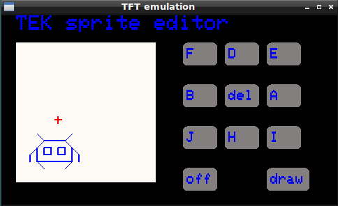
https://github.com/ChrisMicro/GuiPittix … _wrapper.h
Now the LED blinking example and the number example can drive the TEK-display ( dynamically
The other examples require a touch-input which I could not achieve with teraterm. It seems when I click on the teraterm window it is not sending back the mouse position.
Not tested:
// Go to the Graphics-IN mode
void Tekgin() {
Serial.write(0x1B);
Serial.write(0x1A);
} char b0, b1, b2, b3 , b4;
Tekgin(); // set the Graphics-IN mode
Teklocate(200, 600); // from here we want printout results
while(1) {
Tekgin(); // GIN mode
if (Serial.available() > 0) b0 = Serial.read(); // Get pressed buttons/mouse code
if (Serial.available() > 0) b1 = Serial.read(); // cross hair coordinates
if (Serial.available() > 0) b2 = Serial.read(); // cross hair coordinates
if (Serial.available() > 0) b3 = Serial.read(); // cross hair coordinates
if (Serial.available() > 0) b4 = Serial.read(); // cross hair coordinates
Tekalpha(); // go to alpha mode
Tekfont(2);
Tekcolor(6);
Serial.print(b0, HEX);Serial.print(" "); // print out the stuff
Serial.print(b1, HEX);Serial.print(" ");
Serial.print(b2, HEX);Serial.print(" ");
Serial.print(b3, HEX);Serial.print(" ");
Serial.println(b4, HEX);
delay(500);
}Not tested.
// Draw small sprites

void Teksprite(char* sprite) {

Serial.write(0x1E);

Serial.print(sprite);

}I found some github resource which could be useful.
Here is the Fleet consisting of 625 Type 26 frigates, created by
  Tekcolor(green);

char* sprite;

// Type 26 frigate

sprite = "PAAAAAAAAAAAAAADDBBBDDBBBHHBBBDDBBBHHBBHH";

elapsed = micros();

for(i=100; i<600; i=i+20){

for(a=100; a<600; a=a+20){

Teklocate(i, a);

Teksprite(sprite);

}

}

elapsed = micros() - elapsed;

Tekalpha();

Tekfont(normal);

Teklocate(100, 50);

Serial.print("Elapsed: ");

Serial.print(elapsed);
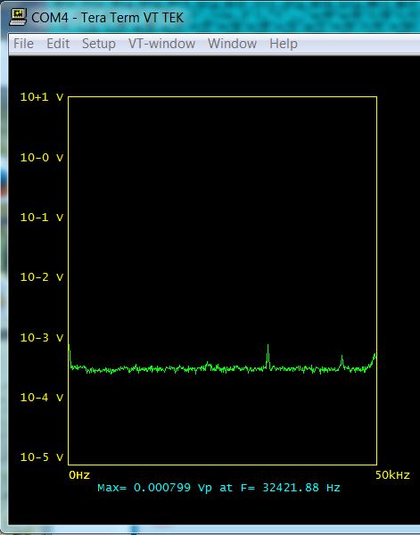
Serial.println(" micros");Fed by my old dyi siggen into the 12bit ADC (Black F407ZE), the ADC input centered by 2x 10k resistors and coupled to the siggen via 100uF cap (all put on a solder-less breadboard, long wires, +Vref is the Black’s Vdd), and the video-streaming done via SerialUSB into the Tek Terminal (TeraTerm Win7).
The Tek terminal is perfectly usable, the Tekcls() and Serial.printing of numbers causes a short blink sometimes, but drawing 512 spectra (lines or dots) itself is fast, realtime. Avoiding the Tekcls() and minimizing Serial.printing will do it realtime.
Below a ~30kHz sin signal:
1. signal’s generator output level at zero – you may see there is still a signal leakage off the siggen output, however (the noise floor is something like 200uVpeak).
2. with ADC not over-driven
3. with ADC over-driven..
- FFT_Siggen_1.JPG (36.85 KiB) Viewed 783 times
This could be really useful.
Putting it into a library would IMHO be the next logic step
Still the none_CLS way of updating the screen content has to be elaborated.
My idea is to rewrite the dynamic information on the screen with the previous information but with black ink (with the background color), thus erase it before writing the new one.
Like:
Tekcolor(green);

Teklocate(200,200);

Serial.print("Hello World");

Tekbox(100,100,700,700);

do_something();

// Delete the above info only, no Tekcls()

Tekcolor(black);

Teklocate(200,200);

Serial.print("Hello World");

Tekbox(100,100,700,700);

// .. deleted from screen
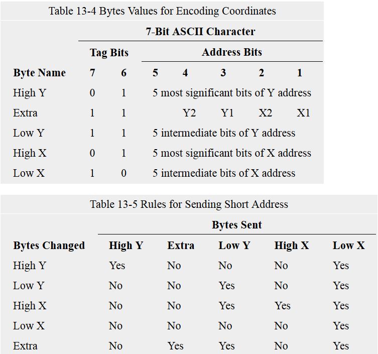
..http://vt100.net/docs/vt3xx-gp/chapter13.html#S13.14
shows following table – how the Tek coordinates are sent, and how the “short version” of sending the coordinates works.
The key message here is, the last byte (Low X) is the byte which triggers the actual beam on, and does the draw..
The Tek includes a 5 bytes large “video buffer” where the internal logic detects the upper 2 bits (the “Tag bits”) of incoming ASCII chars (actually bit 6 and 5 of a byte), and based on the sequence and the value decides what to do next.
When somebody needs the 12bits 4k x 4k mode, an additional “Extra” byte with top bits of each four coordinates must be sent as the second Y coordinate. The terminal shall detect that automatically and enhance the size.
Note: we do not send the Extra byte yet.
- Tek Encoding the coordinates.JPG (72.9 KiB) Viewed 757 times

- Font Artifacts.JPG (15.58 KiB) Viewed 734 times
Not perfect…
#defines should be properties
Please feel free to fix this and generally improve it
The next improvements could be:
1. introducing ie Tekplotv and Tekploth – vertical and horizontal lines with short addressing
2. Tekbox with short addressing
4. introducing the 12bit mode
5. when talking “a perfect library” – the most difficult part would be to create a mechanism for a redraw of the the dynamic information on the Tek screen by overwriting it by the background ink color and printing the new one.
It is basically easy with a couple of values, but when you draw a lot of strings, arrays (in form of lines/dots/sprites), you have to memorize all the “old_values”, and when they change and need to be print out you have to rewrite their picture with the old_value (with background ink color) on the exact same place and print the new value with the actual ink color on the exact same place..
And it is not only a single action like Serial.print or Tekplot(), but it could be a process – ie. to redraw a “spectrum”, “waves”, small picture..
Not easy..
There is a workaround of course – you can Tekcls() and draw a new complete picture with new values, it is fast enough for most apps.
I just put the library files into a folder inside the libraries folder
I wonder if there should be a function to display the text. I know that Serial.print and serial.println work fine, but it seems strange to not need a TEK specific command to do this
I may just add tek.print and tek.println which just call serial.print and serial.println
Also I think it may be useful to pass the serial port to the library as its hard coded to “Serial”
Yes, that is ok.
There is one issue with Serial.print – it cannot print the scientific notation – like: -3.45E-6.
So we have to use something instead, which can do..
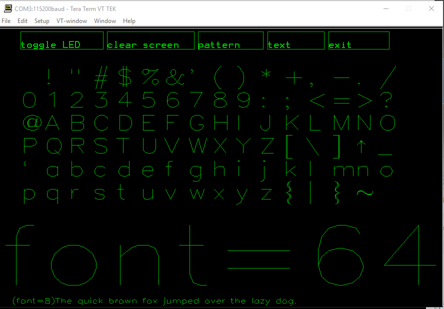
PS: the Tek terminal, when in alpha mode (Tekalpha()), works like a standard “char based terminal”.
The font size parameter (Tekfont(), see our defines in lib) determines its lines/chars volume:
large – 35 lines of 74 characters
normal – 38 lines of 81 characters
small – 58 lines of 121 characters
smallest – 64 lines of 133 characters
The actual font type used could be set in Tek’s Setup->Font.
The color emulation and the background color could be set in Tek’s Setup -> Window.
I did this here.
So all Adafruit-GFX functions use the TEK Terminal as output.
Adafruit is pixel-oriented, tek is vector oriented with the “draw a line from A,B to C,D” as the only graphics primitive..
Rendering adafruits demos with tek emulation may work, but it will take ages, I would guess
// A simple TEK4010/4014 Vector terminal DEMO

// You need TeraTerm or Xterm switched to TEK4010/14 Emulation

//

// Use fast Serial over USB for best experience

//

//  Shows alpha terminal mode

//

// Provided as-is, no warranties of any kind are provided :)

// by Pito 7/2017
#include "Arduino.h"

#include "Tek.h"
TEK tek;
void setup() {

delay(3000);

Serial.begin(115200);

}
void loop() {
uint32_t i;
tek.Tekcls();
tek.Tekfont(normal);

tek.Tekcolor(yellow);

tek.Tekalpha();

tek.Teklocate(100, 700);
for (i = 0; i < 20; i++) {

Serial.println("Hello World from STM32duino!");

}
delay(2000);
tek.Tekcolor(cyan);

char* sprite;

// Type 26 frigate

sprite = "PAAAAAAAAAAAAAADDBBBDDBBBHHBBBDDBBBHHBBHH";

tek.Tekgraph(solid);

for(i=350; i<480; i=i+20){

for(uint32_t a=300; a<400; a=a+20){

tek.Teklocate(i, a);

tek.Teksprite(sprite);

}

}
delay(2000);
tek.Tekfont(smallest);

tek.Tekcolor(green);

tek.Tekalpha();

tek.Teklocate(100, 300);
for (i = 0; i < 80; i++) {

Serial.println("This is a test of Tek Terminal..");

}
delay(5000);
}
We could write some code to turn a scientific notation numbers into a string before sending to serial.print
I have to double check as there is a davekw7x version floating around which has got a bug.
http://www.stm32duino.com/viewtopic.php … =60#p26771
This version below shall utilize the single precision FPU when on.
UPDATE: chnged to 7 digits, fair enough for the single precision..
// ====== float2s(): print out up to 7 digits of input single-precision value

// This version enables single-precision for STM32duino, Teensy 3, etc.

// from double2s version by J.Beale March 2013

// modified from original float2s() posted by davekw7x on December, 2010

// http://arduino.cc/forum/index.php/topic,46931.0.html

// Modded for single precision floats with FPU by Pito 4,7/2017

// No warranties of any kind, provided as-is..
char * float2s(float f)

{

return float2s(f, 2);

}
char * float2s(float f, unsigned int digits) {

int d;

static char s[26];  // formatted number as string

int index=0;
// handle sign

if (f < 0.0f)

{

s[index++] = '-';

f = -f;

}

// handle infinite values

if (isinf(f))

{

strcpy(&s[index], "INF");

return s;

}

// handle Not a Number

if (isnan(f))

{

strcpy(&s[index], "NaN");

return s;

}
// max digits

if (digits > 7) digits = 7;

int exponent = int(log10f(f));

float g = f / powf(10.0f, exponent);

if ((g < 1.0f) && (g != 0.0f))

{

g *= 10.0f;

exponent--;

}

// if (exponent < -330) {  // lower limit of double-precision on Teensy 3

if (exponent < -38) {

g = 0.0f;

exponent = 0;

}

if (digits < 7) {  // display number rounded at last digit

g += 0.5f / powf(10.0f,digits);

}
d = g;

sprintf(&s[index++],"%d",d);

if (digits > 0) sprintf(&s[index++],".");

for (int i=0;i<digits;i++) {

g = (g - d) * 10.0f;  // shift one decimal place to the left

d = int(g);

sprintf(&s[index++],"%d",d);

}

sprintf(&s[index], "e%+d", exponent);

return s;

} // ===== end float2s()
ftp://invisible-island.net/shuford/term … x_news.txt
I found some info on the GIN mode and mouse coordinates:
There are 2 modes of reading the GIN co-ordinates, interactive and

non-interactive.
Interactive mode: the Xhair cursor is displayed, the operator moves it

to the required position and then presses a key (NOT the return key!).

A sequence of bytes is sent to the computeras follows:
The ASCII value of the key pressed e.g. D

HiX byte - 01 followed by the 5 most significant X bits

LoX byte - 01 followed by the 5 least significant X bits

HiY byte - 01 followed by the 5 most significant Y bits

LoY byte - 01 followed by the 5 least significant Y bits
This sequence is followed by the termination character(s) as set by

a jumper set on the TC2 card within the terminal. The most common

setting is to send the CR character.
To recreate the X and Y values:
X=(32*(HiX-32))+(LoX-32)

Y=(32*(HiY-32))+(LoY-32)
In non-interactive mode the computer sends <ESC><ENQ>. The sequence

returned is as above, except that the keycode is replaced by a status

byte, this gives information as to whether the terminal is in Alpha,

Graphics or GIN mode. I cannot at the moment remember which bit does

what.
There is a distinction of 2 cases:
/*--------------------------------------------------------------------------*\

* decode_gin()

*

* Decodes a GIN tek vector string into an xy pair of relative device

* coordinates.  It's best to not use absolute device coordinates since the

* coordinate bounds are different depending on the report encoding used.

*

* Standard:	<HiX><LoX><HiY><LoY>

* Extended:	<HiY><Extra><LoY><HiX><LoX>

*

* where <Extra> holds the two low order bits for each coordinate.

\*--------------------------------------------------------------------------*/
static void
decode_gin(char *c, PLGraphicsIn *gin)
{
int x, y, lc = strlen(c);
if (lc == 4) {
x = ((c[0] & 0x1f) << 5) +
((c[1] & 0x1f) );
y = ((c[2] & 0x1f) << 5) +
((c[3] & 0x1f) );
gin->pX = x;
gin->pY = y;
gin->dX = x / (double) TEKX;
gin->dY = y / (double) TEKY;
}
else if (lc == 5) {
y = ((c[0] & 0x1f) << 7) +
((c[2] & 0x1f) << 2) +
((c[1] & 0x06) >> 2);
x = ((c[3] & 0x1f) << 7) +
((c[4] & 0x1f) << 2) +
((c[1] & 0x03) );
gin->pX = x;
gin->pY = y;
gin->dX = x / (double) (TEKX << 2);
gin->dY = y / (double) (TEKY << 2);
}
else { /* Illegal encoding */
gin->pX = 0;
gin->pY = 0;
gin->dY = 0;
gin->dX = 0;
}
}
Very nice written, easy to read. TT knows more than I expected
Frankly, I cannot find TTerm’s help or documentation for TEK emulation options..
So we have to read the sources.
From what I’ve read the GIN mode returns always 10bit values, even you are in 12bit mode..
TT does in the source:
  ToggleCrossHair(tk,ts,FALSE);

X = (int)((float)tk->GINX /

(float)tk->ScreenWidth * (float)ViewSizeX);

Y = (int)((1.0 - (float)(tk->GINY+1) /

(float)tk->ScreenHeight) * (float)ViewSizeY);

Code[0] = KeyCode;

Code[1] = (X >> 7) + 32;

Code[2] = ((X >> 2) & 0x1f) + 32;

Code[3] = (Y >> 7) + 32;

Code[4] = ((Y >> 2) & 0x1f) + 32;

Code[5] = 0x0d;
I get “[36m20” as the mouse button return code – most probably an escape sequence.
UPDATE:
“[36m” is the escape code for cyan color.
When I changed to yellow, I got [33m – the escape code for yellow.
Thus it returns the actual active color. Interesting.. ![]()
The “0x20” is the code for “space”, that is the default TEKGINMouseCode for left button (tterm .ini).
You may change it.
// A simple TEK4010/4014 Vector terminal DEMO

// You need TeraTerm or Xterm switched to TEK4010/14 Emulation

//

// Use fast Serial over USB for best experience

//

//  Shows MOUSE activity and returned X and Y coordinates

//  You must click to get new X and Y

//

// Provided as-is, no warranties of any kind are provided :)

// by Pito 7/2017
#include "Arduino.h"
#include "Tek.h"
TEK tek;
void setup() {
delay(3000);
Serial.begin(115200);
}
void loop() {
uint32_t i = 0;
char b0, b1, b2, b3, b4;
uint16_t x = 0, y = 0, xo = 0, yo = 0;
tek.Tekcls();
tek.Tekcolor(cyan);
while (1) {
tek.Tekgin();
if (Serial.available() > 0) b0 = Serial.read();
if (Serial.available() > 0) b1 = Serial.read();
if (Serial.available() > 0) b2 = Serial.read();
if (Serial.available() > 0) b3 = Serial.read();
if (Serial.available() > 0) b4 = Serial.read();
x = 32 * (b1 - 32) + (b2 - 32);
y = 32 * (b3 - 32) + (b4 - 32);
tek.Tekalpha();
tek.Tekfont(small);
tek.Tekcolor(cyan);
if ((x != xo) | (y != yo)) {
Serial.print(b0, HEX); // KeyCode
Serial.print(" X=");
Serial.print(x);
Serial.print(" Y=");
Serial.print(y);
Serial.println();
xo = x;
yo = y;
i++;
}
delay(100);
if (i == 80) {
tek.Tekcls();
i = 0;
}
}
}
Can you tell me where it needs scientific notation text strings?
Is this for the coordinates or purely for visual text?
Also…
I think you said it does not do fills ??
Is this because the original hardware was a vectior display?
The coordinates are always integers, 0..4095 for x and y.
The Tektronix 4010/4014 and others are basically very large oscilloscope tubes, with a very long afterglow.
The information painted into the phosphorus by the slim electron beam lasted for an hour at least, unless you did clean screen, which took about 1.5 seconds and the high voltage with the opposite polarity cleaned the charge (causing the glow of the lines) off the screen phosphorus.
Tek is an X-Y Plotter. The screen is like a sheet of paper in an X-Y plotter. The pen’s tip is 1 pixel in diameter.
To fill a 300×300 large box with red color means to do 300 lines 300 pixels long.
Tek knows only a single graphical primitive – a line from (a,b) to (c,d).
In past the large surfaces where filled in with a gitter/mesh made of lines.
I recall some early video games that also used vector displays.
Perhaps we can have Asteriods ![]()
Is there a python based TEK emulator?
Not only games, but all graphical systems since 50ties till late 70ties (CADs, military gadgets – radars, etc) were using these kind of vector displays.
In order to get 4096×4096 “resolution” (even it was not exactly such) in single color you would need 2Mbytes of video ram when talking a raster mode. That amount of ram was quite expensive at that time..
For example the Intel’s 3101 64-bits ram cost $99 in mid 1969, $40 in 1970.
And you needed only one single 3101 chip for the Tek4014
Maybe we can bring Tek to fill out a rectangle if we write a “space” character with the desired color and dimension at the desired coordinate.
Of course, this will only work for horizontally and vertically aligned fills.
I can’t find a definitive source but there is some interesting code in this blog
Maybe we can bring Tek to fill out a rectangle if we write a “space” character with the desired color and dimension at the desired coordinate.
Of course, this will only work for horizontally and vertically aligned fills.
You can do “pseudo fills” if the screen resolutions fits.
You can see the result if you just install the GuiPittix-Library and run the LED-example with TEK-output.
I make this library to have universal graphical elements on any display. Probably I will start to make special vector graphics elements to support this type of displays.
[RogerClark – Mon Jul 24, 2017 10:44 pm] –
I recall some early video games that also used vector displays.Perhaps we can have Asteriods

I recall also Battle Tank and a two player game I don’t remember the name. It was a battle between two battleship in a gravitational field.
was the tank one
I vaguely recall playing something based on Star Trek, with a “Enterprise” and “Kingon” ship (while on a school trip, I think we went to an arcade when we should have been doing something educational! and they had some old game console machines )
Possibly
http://davesclassicarcade.com/startrek/startrek.html
https://en.wikipedia.org/wiki/Star_Trek_(arcade_game)
But the one I remember seemed to predate this, and from what I recall was more like asteroids, in that it was 2D plan view
  uint32_t elapsed = micros();

for (i=100; i<400; i++){

tek.Tekline(i,100,i,400);

}

elapsed = micros() - elapsed;You can set for example the text orientation, 0, 90, 180, 270 deg. That is great when drawing graphs and charts..
[Pito – Tue Jul 25, 2017 8:53 am] –
Btw, why such spread?? (2.897ms – 7.933ms).
I can only think on the host processing speed, the libmaple USB has a 2kB Tx buffer, uses blocking Tx, and if the Tekline() command sends more than 5 bytes, then the buffer gets full and will allow sending of further bytes only if the host is reading some of previously sent ones.
So actually the ~3 ms is the time just to write the data to the Tx buffer.
Its better to find a python TEK 4010 client and add a new command for fills
[stevestrong – Tue Jul 25, 2017 9:39 am] –
So actually the ~3 ms is the time just to write the data to the Tx buffer.
Ok, the 8ms is the realistic time for filling the 300x300box..
That is not bad provided most of potential users may use the Tek emulator for a visualization of their measurements done with their ..duinos in a form of simple 2D graphs/charts, with the option of having easy copy/paste/saving/printing of their graphs. And without a need to mess with windows programming.
I did not test with Xterm, but sources claim it works as well..
PS: while I messed with the spectrum analyzer POC above, the lesson learned is following: the data acquisition – sampling the ADC data – takes much longer than the processing and plotting them in Tek window. For example with 100kHz sampling rate, you need 10msecs to get 1024 samples in, you need to average the spectra in order to get some nice results, I did with 64 spectra, thus the total time for data sampling was 640ms. The actual fft processing of 64 spectra takes maybe 100 msecs in total (fpu on). So the refresh rate of the spectra on the Tek screen was below 1sec. The plotting the data took maybe 15msecs.
There is also a Processing demo: https://github.com/osresearch/vst/tree/ … essingDemo
EDIT
Although this is not Tek but it is a Serial monitor to display graphics, basically converting serial messages to graphical elements using Processing.
Forum: https://forum.arduino.cc/index.php?topic=307293.0
Github: https://github.com/NardJ/HTMLSerialMonitor
It looks very promising, worth to check whether it offers more advantages (speed, definable graphical element diversity) than the Tek emulator.
Forum: https://forum.arduino.cc/index.php?topic=307293.0
This looks interesting. The question is: how fast is the display update compared to the TEK? A fast update could be useful for oscilloscope applications.
@Pito
I just made a Arduino library on GitHub out of it.
What copyright do you have? Is GNU GPL 3 OK?
Here are some sprites:
smile face
PFFDDDEEAAAIIHHHJJBBB DDPIAE DDDPHBDA BBBPAHBD HHAP
space ship
PEEAADEAAAAIHAAIIBBBBBBBBBBBBBB
space invader1
PDEEFIAAAEJIIH DFPHHJ EPBBBBBIFDD APAHBD AAPAHBD DDDD
@Pito
Still open question: What software license for your TEK functions?
BTW: would it be difficult to write a small app for Win for example:
1. a simple window, resizable, max 4096×4096
2. menu: comport settings, font type selection, paper/ink colors.
3. it will interpret the above tek commands..
I think it is a weekend project for somebody who knows-how
![]()
PS: in TeraTerm’s TEK the color n. 0 is the current “paper” color, and color n.7 is the current “ink” color.
The colors 1-6 are as it is defined in the library.
[Pito – Thu Feb 01, 2018 1:04 pm] –
<…>
BTW: would it be difficult to write a small app for Win for example:
Would not Processing be up to the task?
There is also another Windows-only C++ compiler that I played with years ago: Quincy
As I remember, it worked well with the Windows GUI.
Ray
https://forum.arduino.cc/index.php?topic=523751.0
![[Pending Enhancement] RTC values resetting](https://sparklogic.ru/wp-content/uploads/2019/11/nucleo-l476rg-zestaw-startowy-z-mikrokontrolerem-z-rodziny-stm32-stm32l476-90x90.jpg)