MainPort USART
Pins 3 and 4 carry serial TX and RX in USART mode.

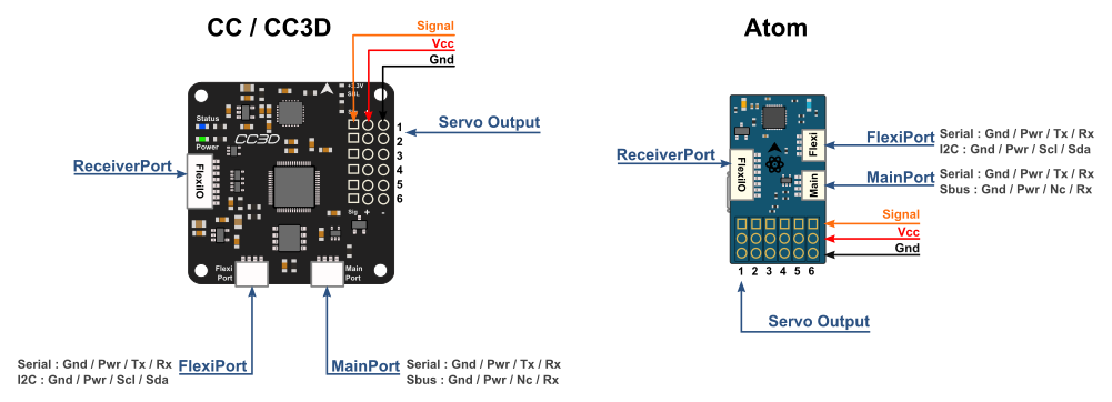
Original CopterControl 3D board connector reference for MainPort, FlexiPort, ReceiverPort, USB and six servo channels.
Tracks the voltage applied through the servo or receiver power rail. USB-only power does not energize the accessory rail.
| Pin | Signal | Direction | Function |
|---|---|---|---|
| MAIN-1 | GND Return | Return | Connect to the board ground return. |
| MAIN-2 | RAW_VCC Unregulated rail | Unregulated rail | Tracks the voltage applied through the servo or receiver power rail. USB-only power does not energize the accessory rail. |
| MAIN-3 | MAIN_TX Output | Output | USART transmit output in serial mode. |
| MAIN-4 | MAIN_RX Input | Input | USART receive input in serial mode. Receiver protocols depend on firmware configuration. |
| FLEX-1 | GND Return | Return | Connect to the board ground return. |
| FLEX-2 | RAW_VCC Unregulated rail | Unregulated rail | Tracks the voltage applied through the servo or receiver power rail. USB-only power does not energize the accessory rail. |
| FLEX-3 | FLEX_TX_SCL Mode-dependent | Mode-dependent | USART transmit in serial mode, or I²C clock in I²C mode. |
| FLEX-4 | FLEX_RX_SDA Mode-dependent | Mode-dependent | USART receive in serial mode, or I²C data in I²C mode. |
| RC-1 | GND Return | Return | Connect to the board ground return. |
| RC-2 | RAW_VCC Unregulated rail | Unregulated rail | Tracks the voltage applied through the servo or receiver power rail. USB-only power does not energize the accessory rail. |
| RC-3 | RC_IO1 Mode-dependent | Mode-dependent | PWM input 1, or PPM input in the modes that select PPM on pin 3. |
| RC-4 | RC_IO2 Mode-dependent | Mode-dependent | PWM input 2 in the appropriate receiver modes. |
| RC-5 | RC_IO3 Mode-dependent | Mode-dependent | PWM input 3, or PWM output 7 in the documented output modes. |
| RC-6 | RC_IO4 Mode-dependent | Mode-dependent | PWM input 4, or PWM output 8 in the documented output modes. |
| RC-7 | RC_IO5 Mode-dependent | Mode-dependent | PWM input 5, or PWM output 9 in the documented output modes. |
| RC-8 | RC_IO6 Mode-dependent | Mode-dependent | PWM input 6, PWM output 10 or PPM input. Check the selected ReceiverPort mode. |
| USB-1 | VBUS Supply input | Supply input | 5 V USB supply contact. |
| USB-2 | USB_DM Bidirectional | Bidirectional | Negative USB differential data contact. |
| USB-3 | USB_DP Bidirectional | Bidirectional | Positive USB differential data contact. |
| USB-4 | USB_ID Unconnected | Unconnected | ID contact is unused for this device connection. |
| USB-5 | GND Return | Return | Connect to the board ground return. |
| OUT1-1 | GND Return | Return | Connect to the board ground return. |
| OUT1-2 | RAW_VCC Unregulated rail | Unregulated rail | Tracks the voltage applied through the servo or receiver power rail. USB-only power does not energize the accessory rail. |
| OUT1-3 | PWM_OUT1 PWM output | PWM output | Signal contact for servo channel 1. |
| OUT2-1 | GND Return | Return | Connect to the board ground return. |
| OUT2-2 | RAW_VCC Unregulated rail | Unregulated rail | Tracks the voltage applied through the servo or receiver power rail. USB-only power does not energize the accessory rail. |
| OUT2-3 | PWM_OUT2 PWM output | PWM output | Signal contact for servo channel 2. |
| OUT3-1 | GND Return | Return | Connect to the board ground return. |
| OUT3-2 | RAW_VCC Unregulated rail | Unregulated rail | Tracks the voltage applied through the servo or receiver power rail. USB-only power does not energize the accessory rail. |
| OUT3-3 | PWM_OUT3 PWM output | PWM output | Signal contact for servo channel 3. |
| OUT4-1 | GND Return | Return | Connect to the board ground return. |
| OUT4-2 | RAW_VCC Unregulated rail | Unregulated rail | Tracks the voltage applied through the servo or receiver power rail. USB-only power does not energize the accessory rail. |
| OUT4-3 | PWM_OUT4 PWM output | PWM output | Signal contact for servo channel 4. |
| OUT5-1 | GND Return | Return | Connect to the board ground return. |
| OUT5-2 | RAW_VCC Unregulated rail | Unregulated rail | Tracks the voltage applied through the servo or receiver power rail. USB-only power does not energize the accessory rail. |
| OUT5-3 | PWM_OUT5 PWM output | PWM output | Signal contact for servo channel 5. |
| OUT6-1 | GND Return | Return | Connect to the board ground return. |
| OUT6-2 | RAW_VCC Unregulated rail | Unregulated rail | Tracks the voltage applied through the servo or receiver power rail. USB-only power does not energize the accessory rail. |
| OUT6-3 | PWM_OUT6 PWM output | PWM output | Signal contact for servo channel 6. |
Pins 3 and 4 carry serial TX and RX in USART mode.
Pin 3 is TX or SCL. Pin 4 is RX or SDA. Select the protocol in the firmware configuration.
ReceiverPort assignments change with the firmware mode. OpenPilot documents PWM inputs, PPM on pin 3 or pin 8, and PWM outputs 7–10.
Use a standard data cable with a USB host for USB configuration.
| Parameter | Limit | Conditions and source |
|---|---|---|
| External supply rail4.8–15 V | 4.8–15 V | The external rail is passed to the peripheral power contacts without regulation. Use USB alone for the bench examples. OpenPilot CC3D Hardware Setup · Ports and pin-outs |
| Serial logic for this fixture3.3 V | 3.3 V | Use 3.3 V logic and a common return. Leave the accessory power pin isolated. OpenPilot CC3D Hardware Setup · Ports and pin-outs |
| USB power5 V from host | 5 V from host | Powers the board for configuration. The accessory rail remains off with USB as the only supply. OpenPilot CC3D Hardware Setup · Ports and pin-outs |
Matches the CopterControl 3D open hardware files. Match the key and PCB labels on your board before connecting a harness.