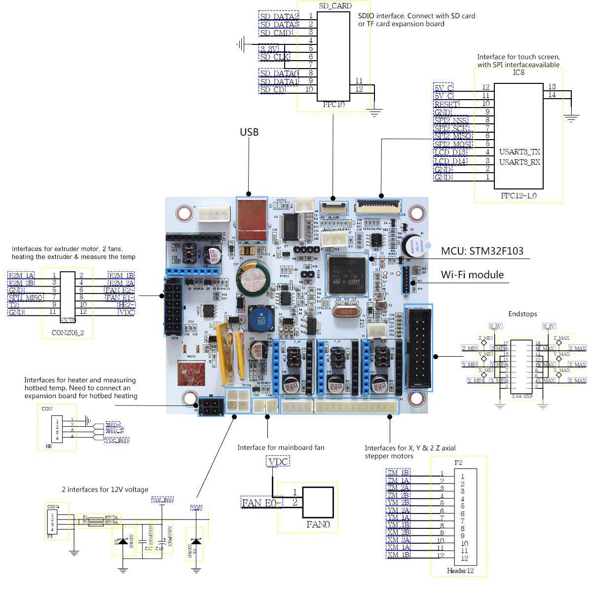
Endstop inputs
Each axis has a minimum and maximum 3.3 V signal with ground and a 3.3 V supply contact in the header.

Original GTM32 printer controller with STM32F103VET6 and separate 12 V inputs for the main electronics and bed.
3.3 V endstop signal for the named axis and travel limit.
| Pin | Signal | Direction | Function |
|---|---|---|---|
| P3-1 | GND Return | Return | Connect to the board ground return. |
| P3-2 | VDC Supply rail | Supply rail | Board power rail. Confirm voltage, source and return from the connector drawing. |
| P3-3 | VDC_BED Supply rail | Supply rail | Board power rail. Confirm voltage, source and return from the connector drawing. |
| P3-4 | GND Return | Return | Connect to the board ground return. |
| HB-1 | GND Return | Return | Connect to the board ground return. |
| HB-2 | BED- Switched load | Switched load | Load connection in the Geeetech diagram. Leave disconnected for the logic-only bench test. |
| HB-3 | BED_T Temperature sense | Temperature sense | Temperature signal in the printer harness. Follow the appropriate expansion board or extruder wiring. |
| HB-4 | VDC_BED Supply rail | Supply rail | Board power rail. Confirm voltage, source and return from the connector drawing. |
| EXT0-1 | E2M_1A Motor output | Motor output | Stepper driver winding output. Connect a motor only after identifying both winding pairs with power removed. |
| EXT0-2 | E2M_1B Motor output | Motor output | Stepper driver winding output. Connect a motor only after identifying both winding pairs with power removed. |
| EXT0-3 | E2M_2B Motor output | Motor output | Stepper driver winding output. Connect a motor only after identifying both winding pairs with power removed. |
| EXT0-4 | E2M_2A Motor output | Motor output | Stepper driver winding output. Connect a motor only after identifying both winding pairs with power removed. |
| EXT0-5 | GND Return | Return | Connect to the board ground return. |
| EXT0-6 | FAN_E2- Switched load | Switched load | Load connection in the Geeetech diagram. Leave disconnected for the logic-only bench test. |
| EXT0-7 | SPI1_MISO Board signal | Board signal | Signal assignment on the numbered manufacturer schematic connector. |
| EXT0-8 | FAN_E1- Switched load | Switched load | Load connection in the Geeetech diagram. Leave disconnected for the logic-only bench test. |
| EXT0-9 | T2 Temperature sense | Temperature sense | Temperature signal in the printer harness. Follow the appropriate expansion board or extruder wiring. |
| EXT0-10 | HE2 Switched load | Switched load | Load connection in the Geeetech diagram. Leave disconnected for the logic-only bench test. |
| EXT0-11 | GND Return | Return | Connect to the board ground return. |
| EXT0-12 | VDC Supply rail | Supply rail | Board power rail. Confirm voltage, source and return from the connector drawing. |
| END-1 | GND Return | Return | Connect to the board ground return. |
| END-2 | GND Return | Return | Connect to the board ground return. |
| END-3 | X_MIN Endstop input | Endstop input | 3.3 V endstop signal for the named axis and travel limit. |
| END-4 | X_MAX Endstop input | Endstop input | 3.3 V endstop signal for the named axis and travel limit. |
| END-5 | 3V3 Supply rail | Supply rail | Board power rail. Confirm voltage, source and return from the connector drawing. |
| END-6 | 3V3 Supply rail | Supply rail | Board power rail. Confirm voltage, source and return from the connector drawing. |
| END-7 | GND Return | Return | Connect to the board ground return. |
| END-8 | GND Return | Return | Connect to the board ground return. |
| END-9 | Y_MIN Endstop input | Endstop input | 3.3 V endstop signal for the named axis and travel limit. |
| END-10 | Y_MAX Endstop input | Endstop input | 3.3 V endstop signal for the named axis and travel limit. |
| END-11 | 3V3 Supply rail | Supply rail | Board power rail. Confirm voltage, source and return from the connector drawing. |
| END-12 | 3V3 Supply rail | Supply rail | Board power rail. Confirm voltage, source and return from the connector drawing. |
| END-13 | GND Return | Return | Connect to the board ground return. |
| END-14 | GND Return | Return | Connect to the board ground return. |
| END-15 | Z_MIN Endstop input | Endstop input | 3.3 V endstop signal for the named axis and travel limit. |
| END-16 | Z_MAX Endstop input | Endstop input | 3.3 V endstop signal for the named axis and travel limit. |
| END-17 | 3V3 Supply rail | Supply rail | Board power rail. Confirm voltage, source and return from the connector drawing. |
| END-18 | 3V3 Supply rail | Supply rail | Board power rail. Confirm voltage, source and return from the connector drawing. |
| P2-1 | ZM_1B Motor output | Motor output | Stepper driver winding output. Connect a motor only after identifying both winding pairs with power removed. |
| P2-2 | ZM_1A Motor output | Motor output | Stepper driver winding output. Connect a motor only after identifying both winding pairs with power removed. |
| P2-3 | ZM_2A Motor output | Motor output | Stepper driver winding output. Connect a motor only after identifying both winding pairs with power removed. |
| P2-4 | ZM_2B Motor output | Motor output | Stepper driver winding output. Connect a motor only after identifying both winding pairs with power removed. |
| P2-5 | YM_2B Motor output | Motor output | Stepper driver winding output. Connect a motor only after identifying both winding pairs with power removed. |
| P2-6 | YM_2A Motor output | Motor output | Stepper driver winding output. Connect a motor only after identifying both winding pairs with power removed. |
| P2-7 | YM_1A Motor output | Motor output | Stepper driver winding output. Connect a motor only after identifying both winding pairs with power removed. |
| P2-8 | YM_1B Motor output | Motor output | Stepper driver winding output. Connect a motor only after identifying both winding pairs with power removed. |
| P2-9 | XM_2B Motor output | Motor output | Stepper driver winding output. Connect a motor only after identifying both winding pairs with power removed. |
| P2-10 | XM_2A Motor output | Motor output | Stepper driver winding output. Connect a motor only after identifying both winding pairs with power removed. |
| P2-11 | XM_1A Motor output | Motor output | Stepper driver winding output. Connect a motor only after identifying both winding pairs with power removed. |
| P2-12 | XM_1B Motor output | Motor output | Stepper driver winding output. Connect a motor only after identifying both winding pairs with power removed. |
| FAN0-1 | VDC Supply rail | Supply rail | Board power rail. Confirm voltage, source and return from the connector drawing. |
| FAN0-2 | FAN_B0- Switched load | Switched load | Load connection in the Geeetech diagram. Leave disconnected for the logic-only bench test. |
| SD-1 | SD_DATA2 Board signal | Board signal | Signal assignment on the numbered manufacturer schematic connector. |
| SD-2 | SD_DATA3 Board signal | Board signal | Signal assignment on the numbered manufacturer schematic connector. |
| SD-3 | SD_CMD Board signal | Board signal | Signal assignment on the numbered manufacturer schematic connector. |
| SD-4 | GND Return | Return | Connect to the board ground return. |
| SD-5 | 3V3 Supply rail | Supply rail | Board power rail. Confirm voltage, source and return from the connector drawing. |
| SD-6 | SD_CLK Board signal | Board signal | Signal assignment on the numbered manufacturer schematic connector. |
| SD-7 | GND Return | Return | Connect to the board ground return. |
| SD-8 | SD_DATA0 Board signal | Board signal | Signal assignment on the numbered manufacturer schematic connector. |
| SD-9 | SD_DATA1 Board signal | Board signal | Signal assignment on the numbered manufacturer schematic connector. |
| SD-10 | SD_CD Board signal | Board signal | Signal assignment on the numbered manufacturer schematic connector. |
| LCD-1 | GND Return | Return | Connect to the board ground return. |
| LCD-2 | GND Return | Return | Connect to the board ground return. |
| LCD-3 | LCD_D14 Board signal | Board signal | Signal assignment on the numbered manufacturer schematic connector. |
| LCD-4 | LCD_D13 Board signal | Board signal | Signal assignment on the numbered manufacturer schematic connector. |
| LCD-5 | SPI2_MOSI Board signal | Board signal | Signal assignment on the numbered manufacturer schematic connector. |
| LCD-6 | SPI2_MISO Board signal | Board signal | Signal assignment on the numbered manufacturer schematic connector. |
| LCD-7 | SPI2_SCK Board signal | Board signal | Signal assignment on the numbered manufacturer schematic connector. |
| LCD-8 | SPI2_NSS Board signal | Board signal | Signal assignment on the numbered manufacturer schematic connector. |
| LCD-9 | GND Return | Return | Connect to the board ground return. |
| LCD-10 | RESET Board signal | Board signal | Signal assignment on the numbered manufacturer schematic connector. |
| LCD-11 | 5V_C Supply rail | Supply rail | Board power rail. Confirm voltage, source and return from the connector drawing. |
| LCD-12 | 5V_C Supply rail | Supply rail | Board power rail. Confirm voltage, source and return from the connector drawing. |
| USB-1 | VBUS Supply input | Supply input | 5 V USB supply contact. |
| USB-2 | USB_DM Bidirectional | Bidirectional | Negative USB differential data contact. |
| USB-3 | USB_DP Bidirectional | Bidirectional | Positive USB differential data contact. |
| USB-4 | GND Return | Return | Connect to the board ground return. |
Each axis has a minimum and maximum 3.3 V signal with ground and a 3.3 V supply contact in the header.
Use the Geeetech SD expansion board and match the FFC orientation.
LCD pins 5–8 expose SPI2. The separate display supply contacts carry 5 V.
Use a standard USB Type-B data cable and the board’s onboard serial bridge.
| Parameter | Limit | Conditions and source |
|---|---|---|
| P3 main supply12 V DC | 12 V DC | Use P3-2 for VDC and verify ground and pin numbering against the schematic. Geeetech GTM32 Board · manufacturer connector circuit drawing |
| P3 bed supplySeparate 12 V DC branch | Separate 12 V DC branch | P3-3 is VDC_BED. Leave this branch open for logic-only tests. Geeetech GTM32 Board · manufacturer connector circuit drawing |
| Endstop logic3.3 V | 3.3 V | Use the board ground reference and check the named signal before attaching a sensor. Geeetech GTM32 Board · manufacturer connector circuit drawing |
Contact numbers follow the original Geeetech circuit drawing. The separate harness illustrations use their own numbering and view. The map covers P3, HB, EXT0, endstops, P2, FAN0, SD, LCD and USB. Confirm any Wi-Fi or other auxiliary connector in its own documentation.